
Abstract
Dynamic analysis is a key problem of flywheel energy storage system (FESS). In this paper, a one-dimensional finite element model of anisotropic composite flywheel energy storage rotor is established for the composite FESS, and the dynamic characteristics such as natural frequency and critical speed are calculated. Through the analysis of acceleration transient response, it is found that the flywheel rotor have two critical speeds during acceleration or deceleration process, which are prone to resonance and damage the bearing. Therefore, in order to avoid resonance or reduce resonance peak, the influence of bearing support stiffness, damping and speed-up rate on the critical speed and resonance peak is studied. The calculation results show that the first two order critical speed are affected by the support stiffness. When the stiffness increases, the critical speed of the flywheel rotor increases, but the growth rate decreases. When the damping increases, the critical speed is basically not affected, and the vibration amplitude decreases rapidly. In addition, the resonance peak value of transient response can be effectively reduced by increasing the speed-up rate.
Keywords
Introduction
With the increasing global energy demand and the wide application of renewable energy, the importance of energy storage technology has become increasingly prominent. As an efficient and reliable energy storage solution, flywheel energy storage technology has attracted much attention in recent years.1,2 However, the critical speed may be included in the wide working speed range of flywheel energy storage system (FESS), resulting in prominent vibration problems. Therefore, it is necessary to carry out dynamic modeling and analysis of flywheel rotor.3,4 Carbon fiber material has been vigorously studied and promoted because of its high strength characteristics, and people have begun to try to add carbon fiber composite materials to the flywheel in recent years. Compared with the metal flywheel, the composite flywheel has lower weight and higher energy storage density, but the composite material has anisotropy, its modeling and dynamic characteristics are more complex and diverse, so the study of its dynamic characteristics has important theoretical and engineering significance.
At present, most of the researches on rotor dynamics of flywheel are metal flywheel. Tang et al. established a finite element model of flywheel rotor, analyzed the critical speed, vibration mode, unbalance response and modal damping ratio of the rotor, and verified the accuracy of the model through experiment.5,6 Wang et al. established a four degree of freedom lumped mass model of flywheel damper by Lagrange method, and calculated the dynamic characteristics of squeeze film damper by finite method. Finally, the calculated response was compared with the experimental results. 7 After that, they used QR damping method to analyze the flywheel system model and iteratively solved the unbalanced response of rotor-bearing system with SFD. The calculated unbalance response and experimental results show the effectiveness of dynamic model. 8 Jiang et al. established a lumped mass model of flywheel rotor, and analyzed the critical speed, modal, and amplitude frequency characteristics. 9 Dai et al. established a lumped mass model of flywheel rotor, analyzed the natural frequency, critical speed and dynamic balance, and verified them by experiment. 10 Kailasan et al. designed a five-axis active magnetic bearing flywheel system and analyzed the dynamics of the rotor system. 11 Nicola and Alexandru established a finite element model of permanent magnet bearing of FESS, and carried out the inherent modal analysis, magnetic field force calculation, and vibration analysis with or without eccentricity. 12 Prince et al. used finite element analysis software to perform static analysis and modal analysis on energy storage flywheel rotor, and studied the deformation failure of the rotor beyond safe speed. 13
Most of the researches on the dynamics of composite flywheel rotors are horizontal rotors rather than vertical. The approximate dynamic models for composite rotors are mainly based on classical beam theory, Timoshenko beam theory and cylindrical shell theory. 14 Zinberg et al. established a helicopter boron/epoxy composite tail rotor drive shaft model using equivalent modulus beam theory, and compared the calculated critical speed with the experimental. 15 Singh and Gupta derived the layered beam theory from the shell theory with a layered displacement field and extended it to solve the dynamics problem of general composite rotors. 16 Sino et al. proposed the simplified homogeneous beam theory of composite rotors. 17 Khoshravan and Paykani used ANSYS to conduct modal analysis of a composite rotating shaft designed based on the classical laminate theory. 18 Alwan et al. conducted simulation and experiment on composite shaft and solid shaft, and compared the two results to verify the accuracy of the model. 19
FESS is a device to realize energy storage and release by controlling the speed up and down of flywheel rotor. Its working principle is as follows: when the system is in energy storage condition, the motor controller controls the motor to drive the flywheel rotor to accelerate, and the electric energy is converted into the kinetic energy, the opposite direction is energy release. FESS is mainly composed of flywheel rotor, bi-directional motor, bearing, power converter, variable frequency speed regulation controller and auxiliary device, vacuum system, and cooling system. 20 The structure diagram of FESS is shown in Figure 1.

Schematic diagram of FESS.
The structures of composite flywheel rotor are shown in Figure 2. The structure of the flywheel rotor can be divided into solid structure and hollow structure. The hollow structure can be divided into external rotor and internal rotor according to the position of stator. The solid structure is shown in Figure 2(a). The flywheel rotor and the motor rotor are arranged up and down in vacuum shell, the structure is compact, but the heat dissipation of the motor needs to be considered. The hollow structure is shown in Figure 2(b) and (c). The flywheel rotor is composed of a lightweight hub and a composite rim on it. The motor is placed in the hollow rotor. The energy stored by the flywheel during operation mainly exists in the composite rim. The rotational speed upper limit is high, so it is often used in high-speed FESSs. 21

Structures of composite energy storage flywheel system: (a) solid structure, (b) hollow structure external rotor and (c) hollow structure internal rotor. 14
The object of study in this paper is hollow structure external rotor. The stator is located in the hub. Both ends of the rotor are supported by radial bearings and supported by passive permanent magnet bearings. Radial and axial protective bearings are installed at both ends to limit the maximum radial and axial displacement of the flywheel rotor.
The finite element model of anisotropic composite flywheel energy storage rotor system is established. The dynamic characteristics such as natural frequency, critical speed, and transient response are calculated, and the effects of bearing stiffness, damping, and acceleration on the critical speed and resonance peak value are studied. The research results may provide theoretical basis for composite rotor design and fault diagnosis.
Modeling of rotor system
In order to establish the dynamic model of the composite flywheel rotor system, the flywheel rotor should be simplified firstly. The model is established by Timoshenko beam element, each element has two nodes, each node has four degrees of freedom, which are translation along x and y directions and the rotation around x and y directions, we can see these clearly from Figure 3.

Timoshenko beam element.
Rotor’s dynamic equation
According to the theory of rotor dynamics, the general form of the dynamic equation of the rotor bearing system can be expressed as:

where,
We need to calculate the kinetic energy, elastic potential energy, virtual work generated by the bearing support force and mass unbalanced force. Then the matrix in Formula (1) can be obtained by substituting them into the Lagrange equation. The basic form of the Lagrange equation is:

where, T and U are the kinetic energy and potential energy of the system respectively;
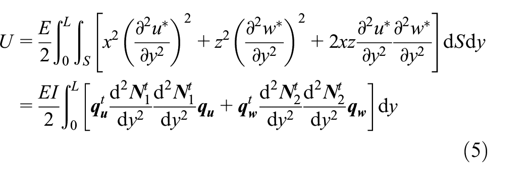
The kinetic energy of a rotating beam element T S can be expressed as 22 :

where, ρ is material density, S is cross-section area, I is moment of inertia.
Substituting Formula (3) into Formula (2) 15 :

where,
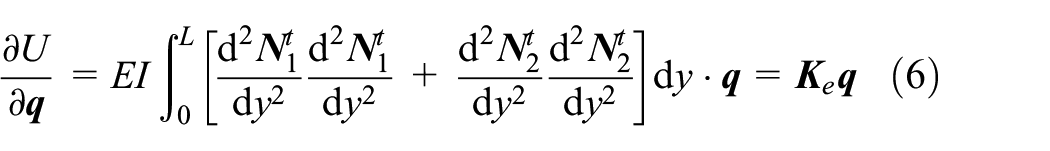
Substituting Formula (5) into Formula (2):
For the modeling of isotropic rotor system, the bending stiffness EI and shear stiffness GA in the stiffness matrix can be directly calculated according to the material properties and material size. However, for the anisotropic composite rotor, it is necessary to transform and accumulate according to the layup of the composite shaft section. This process will be described below.
Constitutive relationship of composite layer
The composite rotor is composed of a hub and a composite rim. The composite rim can be seen as composed of many unidirectional ply composites. A unidirectional ply is shown in Figure 4. The ply angle ϕ is the angle between fiber direction (direction 1) and axial direction of the rotor (z-axis). Direction 2 is perpendicular to the fiber direction, and direction 3 is perpendicular to the ply plane. The unidirectional ply has orthotropic mechanical behavior. The generalized Hooke’s law of orthotropic materials can be expressed by Formula (7):

where,

where, E1, E2, and G12 are the longitudinal elastic modulus, transverse elastic modulus and transverse shear modulus of orthotropic materials respectively. v12, v13, v21, v31 are Poisson’s ratio.

Unidirectional composite ply.
In order to simplify the calculation, the thickness of each layer is very small, and the three-dimensional strain-stress state of each layer can be simplified to a plane state. Therefore, the mechanical behavior of the plane can be characterized by five mechanical constants. Formula (8) can be reduced to:

The above is the stress-strain relationship of the composite plate in the 1-2-3 coordinate system shown in Figure 4. In order to obtain the stress-strain relationship in the x-y-z system, the flexibility matrix needs to be transformed. The transformation relationship is:

where,

Through the transformation matrix, the stress-strain relationship in the x-y-z coordinate can be expressed as:

where:
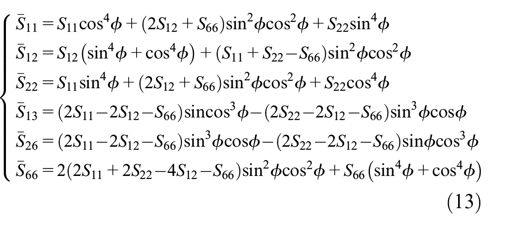
Therefore, the engineering constants of single-layer anisotropic composites in global coordinates can be expressed as 23 :


Composite flywheel rotor modeling
The simplified model is shown in Figure 5. The rotor is a hollow cylindrical structure composed of an aluminum alloy hub and a circumferentially composite rim. The stator in the center of the rotor is ignored. The supporting bearing is simplified to spring-damping structure. Only transverse vibration of the rotor is considered, the radial and axial coupling vibration is ignored. In order to ensure the accuracy and convergence conditions, it is necessary to ensure that the aspect ratio of each element is less than 1. 24 Therefore, the rotor is divided into 14 elements or 15 nodes along the axis, the bearings are placed at node 2 and 14.

Simplified model and finite element division.
According to the last section, the dynamic equation of the composite rotor is shown in Formula (16):

where,
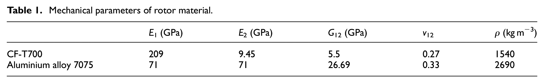
The main geometric parameters of the rotor system are: the total height of the rotor is 1710 mm, the inner diameter of the hub is 380 mm, the outer diameter is 460 mm, the inner diameter of the composite rim is 460 mm, and the outer diameter is 800 mm. The flywheel rotor hub material is aluminum alloy 7075, and the rim uses carbon fiber epoxy resin composite material CF-T700. The mechanical parameters of the material are shown in Table 1. The mechanical parameters of the bearing system are shown in Table 2. The balance accuracy of the rotor is high, the accuracy level is G0.4, and the unbalance is calculated to be 332.9 g mm. It is assumed that the unbalance is loaded on the node 7. The dynamic program of the rotor is written and calculated using MATLAB.
Mechanical parameters of rotor material.
Bearing parameters.

Dynamic characteristics analysis
Critical speed and mode shape
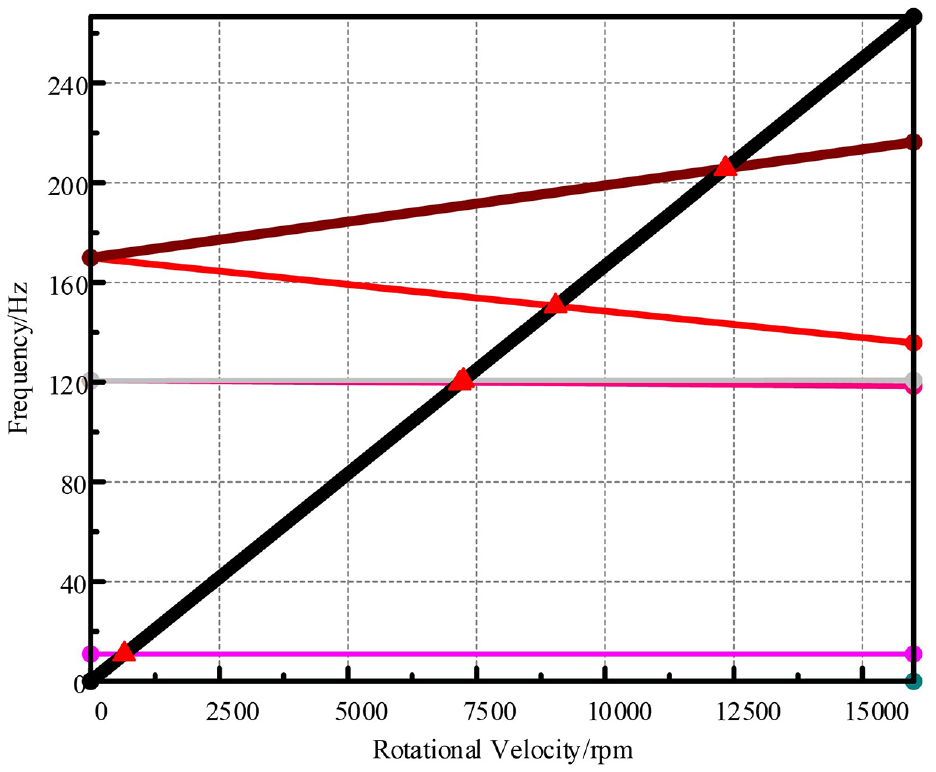
Figure 6 shows the Campbell diagram of the composite flywheel rotor system. The solid lines are the curves of the first and second order natural frequency with the change of rotational speed, and the dotted line is rotational frequency line. Under the influence of gyroscopic effect, the natural frequency of backward and forward whirl varies with the speed. With the increase of speed, the natural frequency of forward whirl increases, and of backward decreases. Since the first-order natural frequency is less affected by gyroscopic effect, the bifurcation characteristic is not obvious, while the second-order natural frequency is greatly affected by gyroscopic effect. The two order frequency curves have four intersections with the rotational frequency line. The rotational direction of the rotor is the same as the unbalanced excitation direction, only the forward whirl can be excited, so the critical speed is the intersection of the forward whirl frequency line and the rotational frequency line. The first-order critical speed is 7294 rpm and the second-order is 12,387 rpm. During the operation, the flywheel rotor must be speeded up and down frequently, so it is necessary to pay special attention to the critical speed within the working speed range to prevent the rotor from generating excessive vibration and causing damage to the entire flywheel system.

Campbell diagram.
Figure 7 shows the first two order mode shapes and whirl orbits of the composite flywheel rotor system. In the figure, “×” is the starting point, “◊” is the end point. Forward whirl is counterclockwise, and backward is clockwise. It can be seen from the diagram that the first order is parallel whirl and the second order is conical whirl.
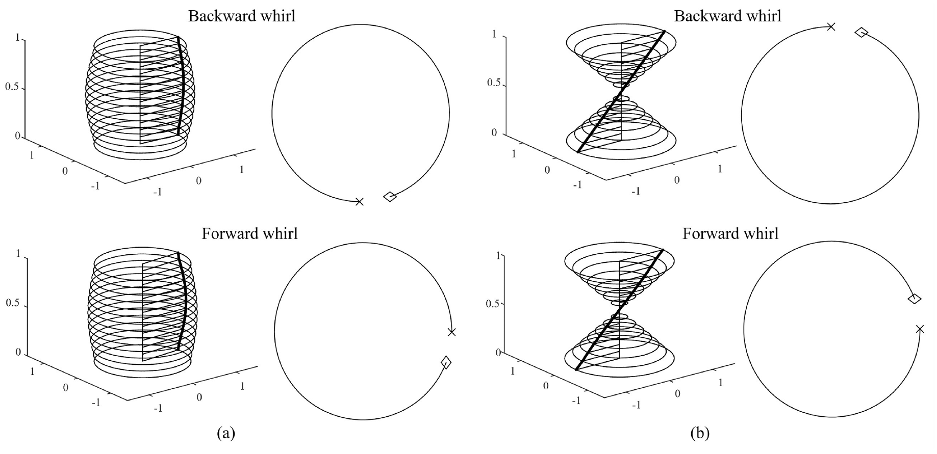
The first two order mode shapes and whirl orbits: (a) first-order mode and (b) second-order mode.
In order to verify the reliability of the model, Ansys software is used to establish a three-dimensional finite element model of the same size and structure. The bearing parameters and positions are unchanged. The calculated Campbell diagram and mode shapes are shown in Figures 8 and 9. The first two critical speed of the three-dimensional finite element model are 7239.8 rpm and 12,342 rpm, respectively. The calculation results of the one-dimensional model are within 5% of the results, which verifies the correctness of the one-dimensional model.
Campbell diagram of three-dimensional model.
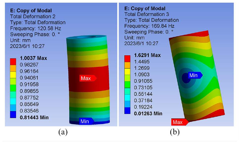
Mode shapes of three-dimensional model: (a) first-order mode and (b) second-order mode.
Influence of support stiffness on rotor vibration characteristics
In order to research the influence of bearing stiffness on the dynamic characteristics of the composite flywheel rotor, the same damping value as the previous section is taken, and the upper and lower bearing stiffness is set to different values in the range of 5 × 10⁷ to 6 × 10⁸ N/m. When the bearing stiffness changes, the vibration response of node 7 and upper bearing of the flywheel rotor is shown in Figure 10. In the range of bearing stiffness, the vibration response curve of the rotor has two peaks, which correspond to the first and second natural frequency. Figure 11 shows the curves of the first and second order critical speed varying with bearing stiffness. When the bearing stiffness increases, the first and second order critical speed gradually increase. When the stiffness is small, the first and second order critical speed increase more obviously, but the growth rate of the first two critical speed will gradually slow down as the support stiffness increases. The growth rate of the first order critical speed is significantly smaller than that of the second order.

Vibration response changes with stiffness: (a) upper bearing and (b) node 7.

The curves of the critical speed varying with bearing stiffness.
Figure 12 shows the curves of first and second order vibration amplitude varying with support stiffness at upper bearing position and node 7. With the increase of the support stiffness, the first and second order vibration amplitude increase. Therefore, in order to avoid the large vibration of the flywheel rotor, the stiffness of the support bearing can be appropriately reduced when other design conditions are met. The first order vibration amplitude is smaller than the second order. Because the first order mode is a translational mode, the vibration amplitude at bearing position is close to the center of the rotor. While the second order mode is a conical mode, the vibration amplitude at the center of the rotor is relatively small, and the vibration amplitude at bearing position is large. Therefore, the second order vibration amplitude at node 7 is much smaller than that at upper bearing position.
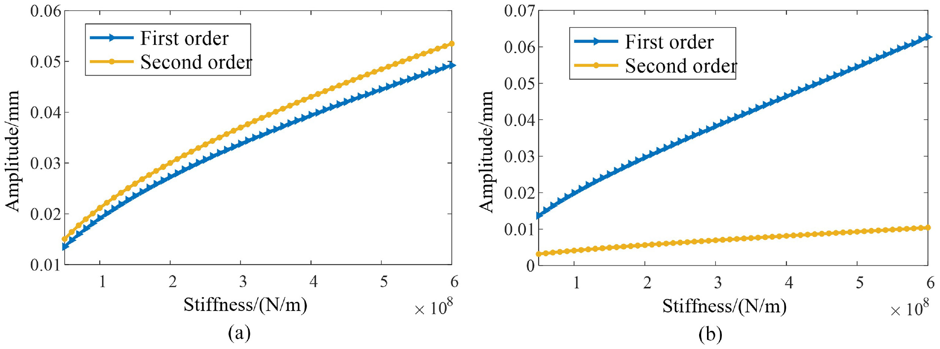
The curves of vibration amplitude varying with support stiffness: (a) upper bearing and (b) node 7.
Influence of bearing damping on rotor vibration characteristics
In order to research the influence of bearing damping on the dynamic characteristics of the composite flywheel rotor, the same stiffness value as in section 3.1 is taken, and the the upper and lower bearing damping is set to different values in the range of 5 × 10³ to 3 × 10⁵ N s/m. When the bearing damping changes, the vibration response of node 7 and upper bearing of the flywheel rotor is shown in Figure 13.
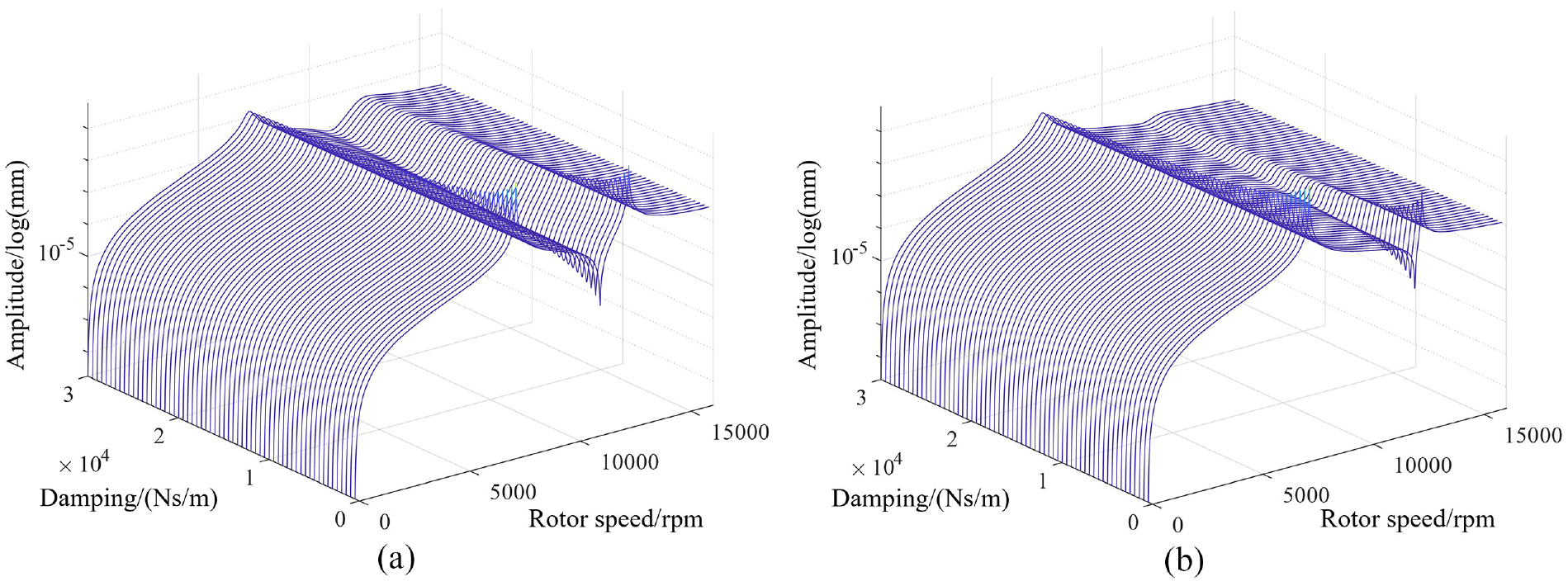
Vibration response changes with damping: (a) upper bearing and (b) node 7.
Figure 14 shows the curves of the first and second order critical speed and vibration amplitude varying with bearing damping. The first order critical speed is not affected by damping, the second-order critical speed increases slowly with the increase of damping. The first and second order vibration amplitude show a significant downward trend with the increase of damping, indicating that the support damping has a strong inhibitory effect on the vibration of the composite flywheel rotor. When the damping is small, the vibration amplitude decreases obviously with the increase of damping, and the decline rate will gradually slow down.

The curves of critical speed and vibration amplitude varying with bearing damping: (a) critical speed and (b) vibration amplitude.
Influence of speed-up rate on transient response
During the operation of FESS, it is necessary to repeatedly control the rotor speed to complete the basic functions of energy storage. Therefore, the flywheel rotor will repeatedly pass through the critical speed falling within the working speed range. In order to avoid the vibration amplitude of the rotor passing through the critical speed is too large, it is necessary to study the method of reducing the amplitude.
In this section, we will solve the transient response at different speed-up rates. The rotational speed increases from 0 to 16,000 rpm. The speed-up rates are 15π rad/s, 30π rad/s, 45π rad/s, 60π rad/s, 75π rad/s, and 90π rad/s respectively. The transient response curves at different speed-up rates are shown in Figure 15. Figure 16(b) shows the curves of resonance peak value varying with speed-up rate. When the rotor passes through the critical speed, the resonance peak value is large at low speed-up rate. The resonance peak is significantly reduced when the speed-up rate increases. So we can increase the speed-up rate to make the flywheel easier to pass through the critical speed. Figure 16(a) shows the curves of critical speed varying with speed-up rate. The critical speed increases slightly with the increase of speed-up rate.

The transient response curves at different speed-up rates.

The curves of critical speed and resonance peak value varying with speed-up rate: (a) critical speed and (b) resonance peak value.
Conclusions
In this paper, the dynamic model of the composite flywheel rotor is established, and the dynamic characteristics of the flywheel rotor are solved. The natural frequency, critical speed and response curve of the flywheel rotor are obtained. The following conclusions can be drawn:
(1) The support stiffness of composite flywheel rotor will affect the critical speed and vibration amplitude. With the increase of stiffness, the critical speed increases, the growth rate slows down gradually, the growth rate of the second order critical speed is higher than that of the first order, and the vibration amplitude also increases. The growth rate of the first order amplitude at rotor center position is obviously higher than that of the second order.
(2) The support damping of the composite flywheel rotor will affect the vibration amplitude, but does not affect the critical speed obviously. When the damping is small, with the increase of damping, the first and second order vibration amplitude decrease rapidly, but the effect is not obvious when the damping is large.
(3) When the flywheel is in the state of uniform speed-up, the speed-up rate will affect the critical speed and resonance peak value. With the increase of speed-up rate, the resonance peak value decreases obviously, the decreasing rate is gradually getting lower, and the critical speed increases slightly.
It can be seen from the above conclusions that if you want to modify the critical speed of the composite flywheel rotor, you can change the support stiffness, and if you want to reduce the vibration amplitude, you can increase the support damping and speed-up rate of the rotor.
Footnotes
Handling Editor: Sharmili Pandian
Author contributions
Conceptualization, Y.W., M.H., R.Z. and H.Z.; methodology, Y.W., M.H., R.Z. and H.Z.; software, Y.W., M.H., H.Z., and Y.L.; validation, Y.W., M.H. and H.Z.; formal analysis, Y.W., H.Z., and Y.L; data curation, Y.W.; writing-original draft preparation, Y.W.; writing-review and editing, Y.W., M.H., R.Z., H.Z., and Y.L.; visualization, Y.W. and M.H.; supervision, R.Z., H.Z., and Y.L.; project administration, Y.W., and R.Z. All authors have read and agreed to the published version of the manuscript.
Declaration of conflicting interests
The author(s) declared no potential conflicts of interest with respect to the research, authorship, and/or publication of this article.
Funding
The author(s) received no financial support for the research, authorship, and/or publication of this article.
Institutional review board statement
Not applicable.
Informed consent statement
Not applicable.
Data availability statement
The data used in the study are available from the corresponding author upon request.