
Abstract
The function of the turbo-pump shaft within the liquid rocket engine is rendered exceedingly complex due to the operation in an environment characterized by drastically low temperatures, elevated velocities, and high pressures. Given these operational conditions, it is highly plausible that a two-phase flow might form within the liquid film located on the terminal face of the mechanical seal. This liquid-vapor mixture significantly modifies the fluid lubrication pattern across the end faces and poses consequential implications on the overall sealing stability. In this study, the phase change characteristics of the fluid in the seal clearance were investigated based on the Laminar and Mixture multi-phase flow models in a spiral groove mechanical seal. The behaviors of two-phase flow characteristics and phase transition under extreme temperature, rotational speed and pressure with liquid nitrogen media were studied. The sealing performance was quantified through metrics including the leakage rate, opening force, and internal gas phase volume ratio. The findings offered valuable insights into the role of operational conditions in influencing the phase change of the liquid film. Moreover, we discerned and explicated the intricate interconnections between the leakage rate, the opening force, and the phase change behavior of the liquid film.
Keywords
Introduction
The high-speed turbo pump represents a pivotal component within reusable low-temperature liquid rocket engines. Functioning as the crucial mechanism to forestall axial leakage of sealing media into the atmosphere, mechanical seals significantly contribute to the performance integrity and reliability of the pump. 1 Nonetheless, these mechanical seals encounter a multitude of challenges, instigated by factors such as heightened density and viscosity of the liquid media and gas condensation under low-temperature conditions. A salient phenomenon manifesting these challenges is the emergence of two-phase flow, culminating in the coexistence of both liquid and gas phases within the sealing components. This concurrence fosters an increase in low-frequency oscillation of seal dynamic and static ring clearances, as well as axial vibration. 2 Furthermore, the influence of gas-phase instability factors may provoke abrupt alterations in the static opening force and mechanical seals’ leakage, consequentially impacting pump efficiency, the longevity, and performance of the sealing components. In extreme cases, these factors could induce functional failure within the entire system. Therefore, elucidating the complexities surrounding two-phase flow phenomena and gas-phase instability issues within mechanical seals operating under low-temperature conditions represents a pressing imperative. Addressing these concerns is a key determinant in augmenting the reliability and performance of liquid rocket engines. 3 As such, our research aims to contribute substantial advancements in this realm, thereby offering prospects for substantial improvements in reusable low-temperature liquid rocket engine design and performance.
Two-phase flow, as a critical phenomenon within the field of mechanical seals, has been the focus of substantial scholarly attention. Hughes et al.4,5 further contributed by investigating the phase change phenomenon in liquid film seals, delineating the implications of phase changes on liquid film seal performance. This research provided theoretical groundwork for the design and optimization of liquid film seals. Furthermore, they established the isothermal and adiabatic limits of phase change within these seals and unearthed the phase change behavior of real-world fluids. Arauz and San Andreä s 6 introduced a theoretical model adept at depicting two-phase flow challenges within low-temperature dampers, corroborating the model’s validity with experimental data. The model offers valuable reference material for the in-depth comprehension of flow behavior in low-temperature damper seals and optimizing seal design. Lau et al. 7 and Yasuna and Hughes 8 independently proposed simplified models for designing two-phase film seals and a continuous boiling model for film seals, respectively. Beeler and Hughes 9 embarked on the exploration of the flow behavior of liquid and gas in two-phase flow at the sealing interface and its impact on sealing performance. Complementarily, Salant and Blasbalg 10 undertook a study on the motion and interaction of two-phase fluids in mechanical seals. Etsion et al.11–13 turned their attention to the hydrodynamic effects of boiling interfaces in two-phase mechanical seals and explored the phase change within misaligned mechanical seals. Wang et al.14–16 evaluated the feasibility and effectiveness of enhancing the friction performance of mechanical film seals using laser surface texturing technology, elucidating the underlying mechanisms. Subsequently, they proposed a homogeneous phase change model predicated on a three-dimensional surface structure to describe the dynamic behavior of two-phase mechanical seals. Lastly, Migout et al. 17 discovered that the influence of the equilibrium ratio on the vaporization phenomenon within liquid films is non-trivial and should not be overlooked. In sum, the academic pursuit of understanding two-phase flow in mechanical seals has resulted in a plethora of models and theories that have advanced our understanding and offered pathways to practical applications in seal design optimization.
Within the Chinese academic sphere, a series of investigations concerning two-phase flow has been conducted under low-temperature media conditions. These investigations included studies involving low-viscosity media such as water, and low-temperature media such as liquid nitrogen. The outcomes of these experiments provided comprehensive insights into the two-phase flow phenomena observed. 18 However, it is imperative to note that the mixed medium model’s main applicability is centered on non-contact mechanical seals lubricated solely by fluid. Consequently, this model fails to encapsulate the entirety of the phase change issue incited by contact friction and liquid film viscosity shear during the mixed friction state of low-temperature media in the start-up phase. Moreover, the dynamic fluctuations in phase change during the high-speed stable phase could potentially induce non-steady-state effects on seal vibration. This issue remains unresolved, indicating a gap in our understanding and modeling of these complex processes. Accordingly, further research is needed to address these challenges and refine the theoretical models of two-phase flow in low-temperature mechanical seals, facilitating more accurate and comprehensive predictions for design and operational optimizations.
The aim of this article is to investigate the ancillary effects potentially inducing boiling or flash vaporization within mechanical seals equipped with spiral grooves at the terminal of the turbine pump shaft. To enhance our understanding of these effects, we undertake an analysis of mechanical seal performance. Wang et al. 19 executed experimental research to collect data on alterations in sealing performance, focusing on variables such as end face temperature, leakage, frictional force, and the friction coefficient, throughout the rapid acceleration process. Jia et al. 20 proposed a gas-liquid two-phase flow lubrication calculation model for spiral groove mechanical seals, and studied the influence of unidirectional flow and two-phase flow on the opening force and leakage. Gu21–24 subsequently contributed to the discourse by discussing and analyzing the phase stability of mixed-phase seals, analogous to liquid and gas phases. Concurrently, Hao et al. 25 conducted simulations of the flow conditions within the end face clearance during the recovery to normal value of the blocked gas pressure of the pump-out spiral groove air film seal. Complementarily, Li et al.26–28 explored the cavitation mechanism of spiral groove liquid film seals. Furthermore, Yang et al. 29 constructed a mathematical model of spiral groove liquid film seals, taking into consideration factors such as radial cone and circumferential waviness, and scrutinized the influence of these factors on the steady and dynamic characteristics of liquid film seals. Rouillon and Brunetière 30 conducted a series of experimental studies on the performance of spiral groove mechanical end face seals under liquid lubrication conditions. Jin et al.31,32 studied the effects of four kinds of easy vaporization sealing media (liquid hydrogen, liquid oxygen, liquid nitrogen, and water) on the phase change and sealing characteristics of spiral groove mechanical seals, and analyzed the stability of spiral groove mechanical seals at high speeds by introducing a thermohydrodynamic model considering the phase change of fluid flow. However, it is pertinent to note that the vaporization model proposed by earlier researchers predominantly focused on the radial flow of the fluid film. This approach proves inadequate when applied to non-contact liquid film seals furnished with dynamic pressure grooves on the end face. Consequently, this paper aspires to bridge this knowledge gap, striving for a more nuanced and comprehensive understanding of the underlying phenomena in these complex mechanical systems. Furthermore, through the in-depth study of the two-phase flow lubrication effect, it provides a new theoretical and experimental basis for improving the sealing performance of the liquid rocket engine turbine pump.
The primary objective of this article is to construct a simulation model specifically tailored to a helical groove mechanical seal. This endeavor will enable us to delve deeper into the exploration of the two-phase flow phenomenon prevalent in mechanical seals. Concurrent with this theoretical development, empirical studies will be conducted to validate the model, allowing us to scrutinize the impact of diverse operating conditions on the formation of a two-phase flow within the liquid film present in the sealing gap. Furthermore, this research will facilitate an in-depth understanding of the operational mechanisms of mechanical seals. Significantly, the outcomes of this research will offer valuable insights instrumental in guiding future engineering designs. This will equip designers and engineers with the necessary knowledge to develop mechanical seals that are not only more efficient but also possess enhanced reliability. In this way, our study contributes not only to the academic understanding of two-phase flow in mechanical seals, but also to practical applications in the design and operation of such systems.
Theoretical models
Governing equations
Multi-phase models
Gas-liquid two-phase flow stands as a representative form of multi-phase flow. Notably, prevalent multi-phase flow models encompass the Volume of Fluid (VOF) model, the Mixture model, and the Eulerian model. Among these, the VOF model is primarily applicable to stratified or free surface flows, while the Mixture and Eulerian models are suited to scenarios where there is a blending or segregation of phases within the computational domain, and the dispersed phase volume fraction exceeds 10%. However, the Mixture model offers the advantage of lower computational costs and enhanced stability, 33 hence, it has been adopted for development in this research. This study encompasses the consideration of the mass conservation equation, the momentum conservation equation, and the gas transport equation of laminar flow and gas-liquid Mixture multi-phase flow. The expressions for these conservation laws are delineated as follows 34 :
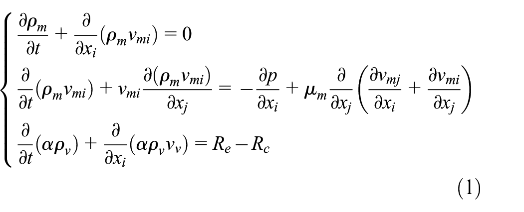
where ρ m refers to the density of the mixture; x i and x j represent any given directions; v mi and v mj denote the mass-averaged velocities in the i and j directions, respectively; μ m stands for the dynamic viscosity of the mixture; α signifies the void fraction; ρ v is the density of the medium gas phase; and R e and R c serve as the source terms for bubble generation and collapse, respectively.
The density of the two-phase flow can be calculated by:

where ρ l is the density of the liquid phase of the medium.
Viscosity of gas-liquid two-phase mixed power can be described as:

where μ m and μ l denote to the dynamic viscosity in gas phase and liquid phase, respectively.
Opening force caused by liquid film pressure between sealing faces can be obtained by:

where F o refers to the opening force; p is the pressure of liquid film end face; r signifies the polar radius; and r o and r i denote to the outer and inner radius of the sealing ring, respectively.
Leakage includes the total amount of fluid involved in lubrication and the side leakage fluid that passes through gaps. 35 The leakage from the lubrication fluid is the necessary flow rate (leakage) Q1 of the fluid film formed by the mechanical seal. It can be expressed as:

where h is the liquid film thickness; μ is the fluid dynamic viscosity.
The side leakage fluid from gaps refers to the fluid side leakage amount Q2 caused by the pressure difference between the inside and outside of the mechanical seal clearance and can be expressed as:

where ρ is the density of fluid medium; v r is the linear velocity of fluid at any radius r.
The comprehensive formula (5) and formula (6) define the total leakage of the seal as Q = Q1 + Q2.
The mass source term for two-phase mass transfer of fluid and gas within sealed gaps is the relationship that characterizes the phase change process, which can be obtained by molecular dynamics theory 36 :

where ψ represents the mass source term, which describes the amount of gas-phase substance produced per cubic meter of space per second; σ is the correction coefficient;
The gas phase volume ratio is defined as:

where B is the gas phase volume ratio and m is the total mass of all substances contained in the liquid film per second.
To ascertain the fluid state, the maximum Reynolds number was calculated utilizing the formula for sealing clearance fluid Reynolds number, as cited in Zhang et al. 37 This computation yielded an estimated value of approximately 1913.21. Given that this value falls within the range conventionally attributed to laminar flow, the laminar flow model was accordingly selected for the numerical study.
Geometrical configuration
The dynamic pressure mechanical seal under investigation in this article employs a spiral groove mechanical seal as a representative example. Figure 1(a) illustrates the configuration of mechanical seal assembly, primarily comprising moving ring, static ring, and bellows. The spiral groove structure on the surface of the mechanical seal ring is shown in Figure 1(b). The parameters r i , r o , and r g respectively signify the inner radius, outer radius, and groove root circle radius of the end face liquid film. Additionally, θ g and θ w denote the angles corresponding to the spiral groove and the sealing dam, respectively. The profile of the spiral groove adheres to a logarithmic spiral form, with the angle between the tangent of any point on the spiral and the tangent of the circle to which it belongs being denoted as the helix angle, represented by the constant θ. In polar coordinates, the equation for the spiral is given as:

where r is the radius of logarithmic spiral; α is the helix angle of logarithmic spiral; and θ is the polar angle along the coordinate axis.

End face structure of low temperature slotted seal: (a) mechanical seal structure and (b) spiral groove of moving ring end face.
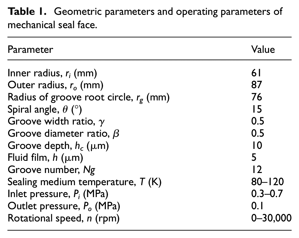
Figure 2(a) indicates the architecture of the liquid membrane, which is bifurcated into two distinct segments: the grooved and the non-grooved liquid films. Figure 2(b) shows the three-dimensional model of the liquid film. Given the extremely small thickness of the liquid film, it is magnified by a factor of 1000 in the thickness direction to facilitate easy observation. For the sake of analytical convenience, the direction from the stationary ring toward the moving ring is defined as the positive Z-axis. The end face of the moving ring is denoted as the plane where z = 0, and the Z axis coincides with the axis of the sealing ring. Table 1 provides detailed geometric parameters of the liquid film as well as the operational conditions of the mechanical seal, including groove width ratio γ = θg/(θw + θg) and groove diameter ratio β = (rg−ri)/(ro−ri). This comprehensive tabulation furnishes a holistic view of the complex mechanical system under consideration, further aiding the analysis and interpretation of the model results.

Liquid film structure of low temperature slotted seal end face: (a) liquid membrane structure and (b) three-dimensional model of liquid film.
Geometric parameters and operating parameters of mechanical seal face.
Grid division and solver setting
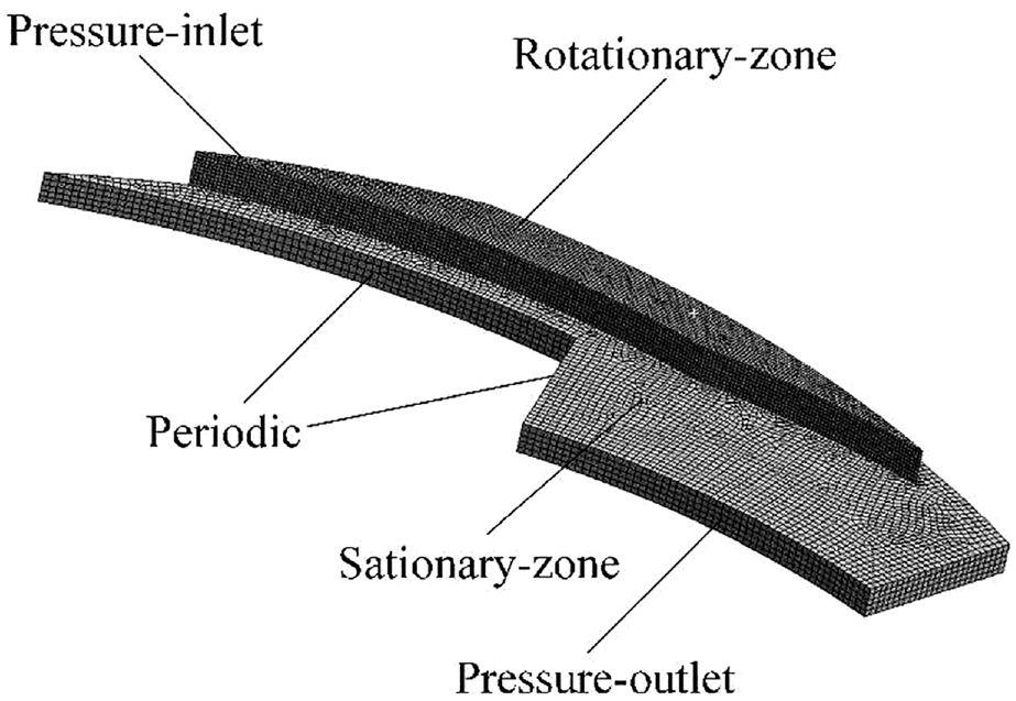
This study is predominantly centered on the analysis of the dynamic pressure of the mechanical seal, with the dynamic ring material comprising silicon carbide, the static ring material constituted by carbon graphite, and the sealing medium is liquid nitrogen, as indicated in Table 2. To conserve computational resources and reduce time expenditures, 1/Ng of the liquid film, owing to the circumferential periodic distribution of the spiral grooves, is employed for simulation calculations. ICEM software is utilized to partition the fluid computational domain into meshes, hexahedron-dominated method is used to divide the grid, and the number of grids is 350,989, as graphically represented in Figure 3, which presents the schematic diagram of the liquid film mesh for a single cycle. It should be noted that all calculated data reported in this paper, such as the opening force, leakage amount, gas phase volume ratio, etc., are exclusively single-cycle calculation results, unless explicitly stated otherwise. Figure 3 shows the specific boundary conditions within the computational model in this study. The pressure-inlet represents the area where the liquid enters the computational domain. It is characterized by specifying the pressure at the inlet to provide the starting point for the flow simulation. The pressure-outlet boundary condition is applied to the outlet of the computational domain, where the liquid flows out. This condition is usually set to a specified pressure, or can be used as an outlet boundary condition, allowing the flow to be adjusted naturally according to the system characteristics. In this computational domain, the periodic boundary condition simulates the periodicity of the spiral groove, allowing the fluid flow and other related parameters to be mapped between the periodic parts, thereby reducing the computational resources required. The rotating region represents the rotating part of the spiral groove. In the context of mechanical seals, spiral grooves are designed to cause fluid motion and improve sealing performance. The boundary condition of the rotating zone considers the influence of the rotation of the groove on the fluid dynamics. The stationary region represents the stationary part of the spiral groove. Contrary to the rotating region, the boundary condition of the stationary region assumes that this part of the groove remains stationary. It considers the interaction between the rotating and stationary parts. These boundary conditions jointly simulate the behavior of the liquid film in the spiral groove mechanical seal. The specified conditions help to capture the complex fluid dynamics inside the seal and provide insight into its sealing performance.
Sealing ring and dielectric material and its physical parameters.

Liquid film meshing diagram.
To discretize the control equations, the finite volume method will be employed, with subsequent resolution utilizing a double-precision, pressure-based solver. The investigation of vaporization characteristics and performance of liquid film mechanical seals with dynamic pressure necessitates reliance on laminar flow models, Mixture models for multiphase flow, and open energy equations. The SIMPLEC algorithm will be deployed in conjunction with the Pressure Staggering Option (PRESTO) format for pressure discretization and second-order upwind formats for momentum and energy. Volume fractions will be handled using the first-order upwind format. For steady-state calculations, the implicit format of the Mixture model will be used for time discretization. Conversely, for transient calculations, an explicit format will be employed. The proposed methodology, utilizing sophisticated computational tools and well-established numerical techniques, ensures an accurate and efficient representation of the complex physical processes under study.
The liquid film possesses its pressure outlet on the outer diameter side. It is posited that the inlet pressure P i maintains a constant state, equivalent to the pressure of the sealing chamber medium. The outlet pressure P i = 0.5 MPa is also assumed to retain constancy, equating to the pressure of the sealing chamber medium during the sealing operation. The inner diameter side features a pressure inlet with its pressure calibrated to the environmental pressure P o = 0.1 MPa and temperature set to the environmental temperature T o = 300 K. Both the pressure inlet and outlet are initialized with a gas-phase volume fraction presumed to be zero. The surface in contact with the dynamic ring, inclusive of the boundaries of the spiral groove, is configured as a rotational wall with a convective heat transfer boundary condition. Silicon carbide (SiC) is chosen as the solid wall material. The surface in contact with the static ring is established as a stationary wall with a convective heat transfer boundary condition, with graphite serving as the solid wall material. As the liquid film thickness is exceptionally minute, existing only at the micron level, to simplify the computation and ensure a degree of accuracy, it is hypothesized that the convective heat transfer coefficient of the liquid film, dynamic ring end faces, and static ring end faces are equivalent. The coefficient’s value can be determined by an empirical formula.
Basic assumptions of end face liquid film flow field
This analysis of the flow field in the end-face liquid film of the spiral groove seal is predicated on fundamental principles of fluid mechanics and incorporates the following suppositions:
The fluid interposed between the sealing surfaces constitutes a Newtonian fluid, exhibiting characteristics of laminar flow.
Volume forces exert no influence over the flow field.
No relative slippage occurs between the fluid film and the two sealing end faces, with the impact of their respective roughness disregarded.
Fluctuations in the system’s vibration, as well as alterations in the dynamic and static rings during the operational process, are not taken into account.
Notably, this computational model omits consideration of end-face deformation triggered by non-uniform force and thermal effects, surface coarseness, waviness tilt, and rotational axis eccentricity. Furthermore, it fails to account for slippage between the two phases, the liquid film, and the surfaces of the dynamic and static rings, nor does it consider the influence exerted by earth’s gravitational pull.
Grid independence test
To mitigate the impact of grid precision on computational results, while also ensuring computational efficiency, a grid independence test was conducted under operational conditions of rotational speed n = 10,000 rpm, inlet pressure P i = 0.5 MPa, and medium temperature T i = 80 K. The resultant data is displayed in Figure 4. The graph reveals a rapid increase in opening force with the augmentation of grid numbers, eventually reaching a state of stability. In the interest of optimizing computational efficiency and minimizing simulation workload, a grid comprising 350,989 elements was utilized for computations in this study.
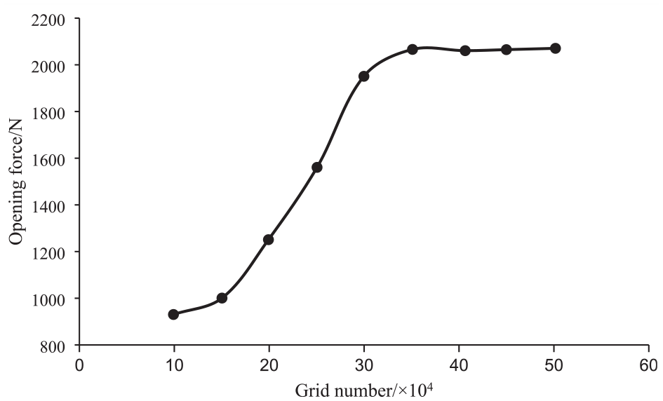
Effect of mesh number on opening force.
Result and discussion
Model validation
As depicted in Figure 5, the leakage rate obtained by simulating the gas-liquid two-phase flow of cavitation phase change and vaporization phase change using the calculation model proposed in this paper is compared with the leakage rate in Liang et al. 38 and Lin et al. 39 The corroboration between the two sets of results underlines the precision and dependability of the proposed model, endorsing its effective applicability in this study.

Validation of the model: (a) validation of cavitation model and (b) validation of vaporization model.
Effect of rotational speed on cavitation phase change and sealing performance
Figure 6 displays the distribution of pressure and phase on the sealing end face at various rotational speeds. As the rotational speed escalates, the dynamic pressure effect similarly amplifies, driving the high-pressure zone to progressively shift toward the groove root. Alongside this, there’s a marked enhancement in the pressure difference from the groove root to the outlet location, precipitating a drastic decline in pressure at the outlet position. This sudden decrease in pressure consequently incites an intense phase transition in the fluid film, thereby escalating the extent of phase change. These results demonstrate the profound impact of rotational speed on the two-phase flow characteristics and phase change behavior within the mechanical seal.

The pressure and phase cloud of 1 × 10⁴ and 3 × 10⁴ r/min: (a) 1 × 10⁴ r/min pressure cloud diagram, (b) 1 × 10⁴ r/min phase cloud diagram, (c) 3 × 10⁴ r/min pressure cloud diagram, and (d) 3 × 10⁴ r/min phase cloud diagram.
In order to better analyze the phase change phenomenon of the liquid film, the value of the gas phase volume fraction along the radius direction of the liquid film is extracted. By observing the law of the phase cloud diagram, the gas phase volume ratio value is extracted along the radius direction through the path of the pressure outlet through the leeward side of the spiral groove until the pressure inlet. The specific data extraction diagram is shown in Figure 7, and the solid line in the figure is the path of extracting the value.

A schematic diagram for calculating data extraction.
Figure 8 illustrates the distribution of the vapor phase on the sealing end face at various rotational speeds. With an increase in rotational speed, there’s a substantial escalation in the phase transition of the liquid film between the sealing end faces. The degree of phase transition of the liquid film sees considerable variation at the outlet and groove locations of the seal. By referencing the gas-liquid volume line for our analysis, we observe that at a rotational speed of 2.5 × 10⁴ r/min, the proportion of the fluid film vapor phase on the sealing end face is sizeable, and the seal’s degree of phase transition significantly amplifies. It can be seen from Figure 8(b) that as the rotational speed continues to increase, the gas volume fraction in the outlet area first enlarges and then contracts along the radius, resulting in a weakening of the fluid film’s phase transition. The primary reason behind this phenomenon is that as the fluid travels from the inlet to the outlet, cavitation progressively ensues. With the cavitation process absorbing heat, the temperature at this location sharply declines in a short span of time, inhibiting fluid phase transition. After the liquid undergoes cavitation, the liquid phase enters the vapor phase, and the phase transition degree reduces, along with the gas volume fraction. This underscores the intricate relationship between rotational speed and phase transition within mechanical seals.

(a) Vapor phase distribution of seal face at different rotational speeds and (b) partial enlarged detail.
Figure 9 illustrates the change in sealing performance parameters at different rotational speeds. The analysis shows that the seal leakage and opening force increase with increasing rotational speed. On the one hand, as the rotational speed increases, the dynamic pressure effect on the sealing end face also increases, resulting in an increase in the opening force. This higher dynamic pressure effect leads to a decrease in the degree of phase transition of the liquid film near the sealing outlet, resulting in a decrease in the volume fraction of vapor phase near the sealing outlet and an increase in the liquid content of the leakage medium. Thus, the mass flow rate of the sealing outlet increases. On the other hand, as the rotational speed increases, the pumping effect of the spiral groove also increases, leading to an increase in the seal leakage. This indicates that rotational speed is directly proportional to the phase change, opening force, and leakage.

Changes of sealing performance parameters at different rotational speeds.
Effect of inlet pressure on cavitation phase change and sealing performance
Figure 10 displays the pressure difference at various inlet and outlet ports, along with the pressure and phase distribution cloud map of the sealing end face. Analysis indicates that an increase in inlet pressure causes the high-pressure area to concentrate toward the slot root position, while reducing the degree of phase change of the liquid film at the outlet position.

The pressure and phase cloud of 0.3 and 0.7 MPa: (a) 0.3 MPa pressure cloud diagram, (b) 0.3 MPa phase cloud diagram, (c) 0.7 MPa pressure cloud diagram, and (d) 0.7 MPa phase cloud diagram.
Figure 11 shows the distribution of vapor phase on the sealing surface under different inlet pressures. The gas-liquid volume line is used as reference for analysis. The increase of inlet pressure obviously inhibits the phase change of the liquid film between the sealing surfaces. The phase change of the film varies greatly at the outlet and groove positions, while the phase composition of the fluid film is relatively stable in other areas. When the pressure is above 0.4 MPa, a reverse cavitation phenomenon is found in the outlet area of the fluid film. In the fluid film, the vapor formed undergoes a reverse phase transition, reverting back to a liquid state. This is attributed to the local pressure drop in the outlet area, which promotes the occurrence of reverse phase transition. 40

Vapor phase distribution of seal face at different inlet pressures.
Figure 12 indeed provides a clear overview of how different inlet pressures affect the performance of a mechanical seal. As outlined, an increase in inlet pressure translates into a higher pressure differential between the inner and outer sides of the seal. This promotes fluid flow within the end-face clearance, leading to an uptick in leakage. Furthermore, the opening force of the seal face rises with increasing inlet pressure. This is attributed to the fluid dynamic pressure effect and static pressure effect, which provide an opening force to the end face once the seal is fully opened. This opening force is counterbalanced by the closing force supplied by the fluid medium and the elastic elements on the inner and outer sides of the sealing ring. The research underscores a strong direct relationship between inlet pressure and various factors, such as the phase change, opening force, and leakage rate of the mechanical seal. Therefore, maintaining an appropriate inlet pressure is vital for optimal mechanical seal operation, minimizing leakage, and ensuring long-term durability.

Variation of sealing performance parameters under different inlet pressures.
Effect of liquid film temperature on vaporization phase transition and sealing performance
Figure 13 shows the pressure distribution and phase diagram of the sealing end face at different liquid film temperatures. Analysis shows that with the increase of liquid film temperature, the pressure in the high pressure area at the slot root gradually decreases. The inlet and outlet regions have lower temperatures and weaker phase transition due to the pumping effect and high flow rate. At the slot root, the temperature rises due to viscous shear heat, accelerating the phase transition of the sealing medium.

The pressure and phase cloud of 80 and 120 K: (a) 80 K pressure cloud diagram, (b) 80 K phase cloud diagram, (c) 120 K pressure cloud diagram, and (d) 120 K phase cloud diagram.
Figure 14 shows the vapor phase distribution of the sealing end face under different liquid film temperatures. The gas-liquid volume line is used as reference for analysis. The increase in liquid film temperature significantly intensifies the vaporization phase change of the liquid film between the sealing end faces. This arises from the gradual increase of the liquid film temperature, with the influence of the dynamic pressure effect of the liquid nitrogen medium, its volume and pressure are also changing, and the synergistic effect culminates in an enhanced the vaporization ability under this condition. The phase change of the film varies greatly at the outlet position and groove root position, while the phase composition of the fluid film has similar trends in other parts. The gas-liquid equilibrium zone appears only in the groove root area when the liquid film temperature is 120 K.

Vapor phase distribution of seal face at different liquid film temperatures.
Figure 15 shows the changes in sealing performance parameters at different liquid film temperatures. Analysis of the graph reveals that the sealing opening force increases with the increase in liquid film temperature, which may be primarily due to the two-phase flow characteristics formed during the sealing process. As the liquid film temperature increases, the liquid phase saturation pressure also increases. Therefore, as the liquid film temperature increases, the fluid in the sealing gap is more likely to exhibit a two-phase flow state. At 120 K, the gas phase volume ratio is the highest. As a result, the internal liquid film of the mechanical seal is more likely to transform into a gas-lubricated, quasi-dry gas seal in the gap when the liquid film temperature is higher. The opening force will increase significantly due to the effects of compressibility of the gas-liquid mixture. The sealing leakage decreases with the increase in medium temperature, which is due to the high gas phase volume ratio of liquid nitrogen at this temperature, resulting in a decrease in the viscosity of the mixed medium and hence a decrease in leakage. This means that the liquid film temperature has a significant impact on phase change and sealing performance.

Changes of sealing performance parameters at different liquid film temperatures.
According to the research of our research group on single-phase flow, the results and phenomena in theoretical calculation and experiment are described and summarized in detail. 20 By comparing the data and rules, the following conclusions are drawn:
In the application background of spiral groove mechanical seal in this paper, liquid medium is more prone to phase transition due to medium characteristics, pressure, and temperature conditions. Therefore, the two-phase flow caused by the working conditions in this paper may be closer to the actual situation.
Compared with the single-phase flow, the two-phase flow has a lower opening force: due to the presence of vapor phase, the sealing contact area of the two-phase flow is smaller, thereby reducing the opening force. This means that less force is required to start or stop the device, improving the ease of operation.
Compared with the single-phase flow, the two-phase flow has a lower leakage: the vapor phase of the two-phase flow can form an isolation layer on the sealing surface to reduce the risk of liquid leakage. The presence of vapor phase can reduce the contact between the sealing surfaces, thereby reducing the possibility of leakage.
Conclusion
This study delivers crucial insights into the performance of turbo pump seals, focusing on the impact of different operating parameters including rotational speed, inlet pressure, and film temperature on phase change and sealing performance. Here are the key findings:
Higher rotational speeds contribute to an enhanced dynamic pressure effect within the film, leading to an increased opening force and leakage, and intensified phase change. Countermeasures are required to address these effects and ensure optimum operation.
Inlet pressure is a primary factor affecting the opening force of the film. In the design stage, an appropriate inlet pressure range must be selected to ensure film stability and sealing performance. Simultaneously, raising the inlet pressure can weaken the static pressure effect, resulting in a reduced gas phase volume fraction and an increase in opening force and leakage.
Film temperature significantly impacts the corresponding saturation temperature of film vaporization. Lower temperature mediums are susceptible to vaporization during film operation. Conversely, higher film temperatures can escalate the opening force, decrease leakage, and induce a rise in gas phase volume fraction. Therefore, effective management of film temperature in turbo pump designs is essential to secure sealing performance and operational efficiency.
It’s important to note that these findings are based on theoretical analyses. Future work will entail experimental research to further explore the phase change phenomenon in film sealing of helical grooves. The insights from these investigations will further augment our understanding and aid in designing more effective and efficient turbo pump seals.
Footnotes
Handling Editor: Chenhui Liang
Declaration of conflicting interests
The author(s) declared no potential conflicts of interest with respect to the research, authorship, and/or publication of this article.
Funding
The author(s) disclosed receipt of the following financial support for the research, authorship, and/or publication of this article: The authors would like to acknowledge the support of the National Natural Science Foundation of China (Grant Nos 52108285).