
Abstract
The virtual microgravity training system based on cable drive usually uses a force-position hybrid control strategy which has following problems: the force control method is sensitive to load disturbances, variable stiffness characteristics of cables reduce the control accuracy of PID controllers, and the expected tension fluctuations are large. These will affect the control accuracy, and further affect the tactile sensation and training effectiveness of astronauts. For the above problems, an all-position type control strategy is proposed to improve the system control accuracy. This strategy uses a compliant control method. In this method, elastic elements are connected in cables, the conversion model of tension and displacement is established, and the tension control is realized by the displacement control which has characteristics of high control accuracy and strong resistance to load disturbance. The PID controller is replaced by the active disturbance rejection controller. In this controller, the tracking differentiator is used to reduce high frequency noises of the input signal, and the extended state observer is used to estimate and compensate the error caused by the change of the cable stiffness. A tension distribution method is designed to make expected cable tensions approach the average tension to reduce the tension fluctuation. The experimental results show that compared with the force-position hybrid control strategy, the all-position type control strategy reduces the tension error and speed error by about 51% and 33% respectively.
Keywords
Introduction
With the development of space station and deep space exploration technology, astronauts need to complete more and more space missions. 1 The motion properties of objects in space are different from those of the Earth’s gravity environment. 2 Due to the inability to feel gravity, the device is prone to collisions during the operation of the device by astronauts such as moving the device and dismantling the device, resulting in device damage. There are even cases of damage to astronauts due to astronauts move heavy loads, such as tearing space suits. Therefore, it is necessary to carry out virtual microgravity training for astronauts on the surface of the earth, so as to avoid safety accidents. 3
At present, there are two classical virtual microgravity training methods, motion method and force balance method. A typical case of motion method is the use of parabolic flight movements by National Aeronautics and Space Administration (hereinafter referred to as “NASA”) to simulate microgravity. This method can expose all objects inside the aircraft (including astronauts) to a virtual microgravity environment. 4 For a long time, these methods have been widely used in various astronaut virtual microgravity training tasks due to the high simulation accuracy and mature technology. However, these methods have problems such as high costs, short single training time, low safety, inability to operate and carry large objects (such as a 5-ton solar panel), and difficulty in changing the parameters of the operating object. For example, Babaghasabha et al. designed a parallel robot based on force balance method and proposed an adaptive robust sliding mode controller based on uncertainty upper bound adaptation to reduce tremors. 5 In order to solve the shortcomings of the classical virtual microgravity methods, the relevant institutions have designed a haptic interactive virtual microgravity training system based on cable driven (hereinafter referred to as “HIVMTS”).
As the requirements of deep space operations become more complex and diverse, astronauts need a training system with better tactile sensation. Astronaut’s tactile sensation is positively correlated with the force control accuracy and motion control accuracy of the system, 6 so a higher accuracy training system is needed. At present, the research on HIVMTS is in its infancy. In terms of mechanical structure, HIVMTS uses a winding device to store cables. The winding device has the advantages of small size and large range of cable retraction and release. Its disadvantages are that the transmission accuracy is low and the cable is easy to entangle. In terms of control, at first, HIVMTS used a cable tension control strategy. The principle is that all cables are controlled by force servo control, and the desired motion law is realized by controlling the resultant force acting on the end effector. However, since the control target is force rather than motion, the control strategy has the problem of poor motion accuracy of the end effector and difficulty in practical application. For example, the one-dimensional virtual microgravity system designed by Wang et al. uses a cable tension control strategy. They also proposed a velocity planning algorithm based on high-order dynamic constraints to improve the planning speed. 7 In order to solve the problems existing in the cable tension control strategy, the current HIVMTS is more inclined to use the force-position hybrid control strategy. For example, Xue et al. used a force position hybrid control strategy in a planar 4-cable virtual microgravity training system, which significantly improved the stability of the system. 8 The principle is to realize the motion control of the end effector by controlling a part of cables’ displacement. 9 Tensions of all cables are generated by controlling tensions of another part of cables. 10 However, this strategy prevents the further improvement of control accuracy due to the large fluctuation of cable target tension, the classical force control method is sensitive to disturbance, and the uncertainty of parallel cable system model.
In order to solve the problems of HIVMTS, on the one hand, we use screw nut mechanisms instead of the winding mechanisms in cable drive units. The screw nut mechanism avoids the transmission error caused by the change of the winding radius of the cable, reduces the return clearance caused by the reducer, and improves the control accuracy of the system. On the other hand, we proposed an all-position type control strategy, which improves the control accuracy from the following three points. First, a new tension distribution method is designed to reduce the fluctuation of the target tension, thereby reducing the fluctuation of the driving load and the burden of the control system. So this method improves the tension control accuracy and motion control accuracy. Secondly, a compliance control method is used to control the tension of the cable, which avoids the problem that the classical force control method is sensitive to disturbance and improves the tension control accuracy. Thirdly, an active disturbance rejection controller is used to control the cable displacement, so as to avoid the use of accurate parallel cable model and improve the accuracy of motion control. After the above improvements, the new haptic interactive virtual microgravity training system based on cable driven can make the trainees have better tactile sensation. Due to the use of active control methods, the parameters of the operated object can be set in real time and arbitrarily by the software.
The remaining chapters of this paper are as follows: Section 2 lists the related work of astronaut virtual training and the research objectives of this paper. In section 3, the principle of the newly proposed all-position type control strategy is described in detail. In section 4, the working principle of HIVMTS and the improvement of cable drive units are described. In Section 5, the astronaut operation virtual object experiment was carried out. The experimental results show that the proposed control strategy effectively improves the control accuracy and has better adaptability to the change of virtual training object.
Related works and objectives of this research
Since the 1980s, the motion method and the force balance method have been used as two classical virtual microgravity methods.
Motion method is the earliest virtual microgravity method, which is characterized by high simulation accuracy. The principle of the motion method is to use all the gravity to provide the acceleration required for the movement of the object, so as to eliminate the influence of gravity. Motion methods include parabolic flight method and falling tower method. The parabolic flight method was first used by NASA in the United States; the falling tower device of Bremen in Germany was put into use in 1990, which is one of the largest ground microgravity facilities in the world and provides a free fall time of 4.74 s (9.3 s using the catapult). 11 Disadvantages of the motion method are short training time, long preparation time and high costs.
The principle of the force balance method is to use buoyancy or mechanical suspension to offset some or all of the gravity of the object. This method solves the shortcoming of the short training time of the motion method. The force balance method includes air flotation method, magnetic levitation method, neutral pool method and suspension method.
Air flotation and magnetic levitation methods can accurately simulate microgravity environments. For example, a microgravity trainer using air suspension was designed by Zhou et al. In his research, the bearing capacity of air bearings under different air pressures was obtained by experiments. The research provides new ideas for the development of multi degrees of freedom (hereinafter referred to as “DOF”) space microgravity simulation technology 12 ; The European Space Agency (ESA) conducted magnetic levitation virtual microgravity experiments on superconductors, 13 breaking through the technical difficulties of liquid suspension in the past. The superconducting and water-cooled electromagnetic systems of ESA have the characteristics of larger working space and longer levitation time. However, when using these methods to achieve spatial motion, the equipment is complex and costly, and it is difficult to simulate the motion of large objects.
The neutral pool method is the most widely used. Sun et al. designed a microgravity liquid buoyancy box that combines water buoyancy with electromagnetic buoyancy to simplify the balance process. They also proposed a compensation control system based on active disturbance rejection control, which achieves online estimation and compensation of water resistance. 14 Wang et al. designed an underwater cable drive system. The system achieves microgravity simulation of the robotic arm under different postures by adjusting the buoyancy of each part of the system and provides a theoretical basis for the combination of neutral pool method and suspension method. 15 However, due to the resistance of the liquid, the simulation accuracy of the above equipment is not high, and astronauts need to be equipped with diving suits, which brings inconvenience to training. 16
The SM2 space mode robot designed by Camegie Mellon University in the United States is a typical passive suspension system that can achieve three-dimensional spatial motion. But it has the problem of low simulation accuracy due to the resistance caused by the mechanical structure. Fujitsu Machinery and Electronics Research Laboratory in Japan has developed an active suspension microgravity system. The system adopts traditional disturbance observers and coupled disturbance observers for online estimation and compensation of Coulomb friction and coupled disturbance of cables. Compared to passive suspension systems, the simulation accuracy is high, but the dynamic range of the operated object is low, and the system structure is complex and costly. 17
The above classic virtual microgravity methods have different characteristics, but none of them can simultaneously meet the requirements of low cost, unlimited single training time, unlimited mass of virtual operated objects, high safety, and the ability to change operated object parameters in real time. These requirements are very important for increasingly heavy space work tasks. In order to meet these requirements, relevant scholars have developed HIVMTS in recent years. This is due to the rapid development of parallel cable drive technology. 18 For example, August Design has developed a video recorder system called SkyCam with four cables, which can reach a maximum speed of 44.8 km/h and is widely used for high-speed tracking photography. Relevant scholars have conducted research on this technology in multiple aspects such as trajectory planning, 19 dynamics, 20 workspaces, control, 21 and collision. For example, Li et al. conducted point-to-point waist training trajectory planning based on cycloidal functions and obtained waist motion trajectories with good compliance. Pang et al. added a shoulder joint bias mechanism to a cable driven robotic arm, thereby increasing the workspace. Li et al. proposed a novel numerical approximation method for cable drive systems to improve control accuracy and reduce computational costs. The principle of HIVMTS is to use cables to suspend an object and use servo systems to drive cables movement, thereby offsetting the gravity of the object and actively controlling the pose of the operated object (end effector), so that the motion of the operated object conforms to the microgravity environment motion law of the object.
At present, research on HIVMTS is in its early stages. In terms of mechanical structure, HIVMTS uses winding devices to store cables. The disadvantage of this structure is that the cable transmission accuracy is low and it is easy to entangle. 22 In terms of control, initially HIVMTS used a cable tension control strategy, such as the four cable space virtual motion robot designed by Laval University in Canada, which can simulate collisions between objects of different shapes and has three DOF 23 ; Zou et al. analyzed the stiffness of the astronaut training system and improved the tension control strategy based on the system stiffness to enhance smoothness 24 ; And the parallel cable driven virtual robot which has improved in terms of workspace and control accuracy was designed by the team in which the author participated. 25 The systems that use this control strategy in other fields include the variable stiffness parallel cable drive mechanism designed by Zhang et al. 26 The parallel series hybrid joint proposed by them has the characteristics of light structure and large workspace. However, the disadvantage of the cable tension control strategy is that the motion control accuracy is low and difficult to apply in reality. 27
At present, HIVMTS tends to use force position hybrid control strategy to compensate for the shortcomings of cable tension control strategy, such as Mini IPAnna3 developed by the Fraunhofer Institute of Manufacturing Engineering and Automation in Germany 28 ; There is also the Charlotte robot developed by NASA, which uses VR technology and cable driven system. VR technology has increased the sense of presence and immersion for astronauts during training. 29 In other fields, this control strategy has many applications, such as Fortin-Cote et al. proposed a control method combining speed closed-loop and admittance controller for a four cable parallel robot which improves the robustness of the control system 30 ; Park et al. designed a remote-controlled robot based on cable drive, solving the problem of multi machine collaborative control. 31
The control accuracy affects astronaut’s tactile sensation, 32 but there are still three problems in the force-position hybrid control strategy that prevent the further improvement of control accuracy. First, the target tension of the cable fluctuates greatly. Some scholars have proposed some tension distribution methods to solve the cable tension in the redundant drive system. For example, Song et al. used the graphical method to calculate the cable tension of the virtual microgravity robot, reducing driving energy consumption. 33 Gouttefarde et al. proposed a general tension distribution algorithm for parallel cable robots, which improved the calculation speed. 34 Mousavi et al. designed a fast and safe tension distribution scheme to improve safety during operation. 35 These methods are designed based on indicators such as energy saving and driver performance utilization. The fluctuation of the cable tension is large, resulting in a large burden on the control and drive system. Second, the classical force control method of the force-position hybrid control strategy is sensitive to disturbance. 36 Third, the parallel cable model is nonlinear and its accurate mathematical model is difficult to obtain. Zhang et al. have pointed out that the model uncertainty of the parallel cable system will have a significant impact on the control accuracy. 37 This is because the existing controllers are linear or model-based. For example, Aflakian et al. designed a target tracking-oriented suspension robot and an astronaut physical exercise device which used a model-based controller to reduce control errors.38,39
In summary, in order to further improve the control accuracy, it is necessary to solve the problems of HIVMTS. Therefore, the main research objectives of this paper are as follows:
(1) Firstly, the principle of the all-position type control strategy and its improvement compared with the classical force-position hybrid control strategy are described in detail. The strategy includes the microgravity environment model, the new tension distribution method, the tension control method based on compliant control and an active disturbance rejection controller.
(2) Secondly, the working principle of HIVMTS is described, and a new driving mechanism was adopted to improve the mechanical transmission accuracy.
(3) Finally, an HIVMTS experimental platform is built. An experiment was designed to simulate astronaut operating the object in space microgravity environment. The effectiveness of the all-position type control strategy and its adaptability to the change of virtual training target are verified by experiments.
The all-position type control strategy of training system
Overall control principle
The cable cannot withstand pressure. In order to maintain all cables in tensile force, the driving number of HIVMTS must be greater than the DOF. 40 That is, the system is a redundant drive system. 41 In order to reasonably control the redundant drive system, the existing HIVMTS adopts a hybrid force-position control strategy (hereinafter referred to as “SF control strategy”). The principle is to divide all the cables into two groups, namely the pose-controlling group cables (hereinafter referred to as “LP”) and the tension-controlling group cables (hereinafter referred to as “LF”). The number of cables of LP is equal to the number of DOF of the end effector, and its role is to control the pose of the end effector. The target pose of the virtual object is converted into the displacement of each cable by using the cable length calculation model (inverse kinematics formula), and the pose of the end effector is indirectly controlled by controlling the displacement of the LP. The role of LF is to provide tension for the cable, so that tensions of all cables are positive. Since the tension values of the redundantly actuated cable are not the only solution, a tension distribution algorithm is needed to determine the tension of the LF.
The schematic diagram of the actuator is shown in Figure 1. The red cables are LP (L1∼L6), and the blue cables are LF (L7, L8). Cables drive the end effector to move, so as to control the pose of the end effector and realize the spatial 6 DOF motion, that is, the displacement in the x, y, z directions and the rotation around the x-axis, y-axis, and z-axis.

The actuator of training system.
In order to improve the control accuracy of HIVMTS, the classical SF control strategy is improved, and a parallel cable all-position type control strategy (hereinafter referred to as “SS control strategy”) is proposed, as shown in Figure 2. The SS control strategy can make trainers have a better feeling of interaction force and its characteristics are as follows:
(1) A new parallel tension distribution method is designed. The purpose of this method is to minimize the variation range and speed of the cable tension during the astronaut training process, and to avoid the impact on the system accuracy and stability due to the system stiffness and load changes too fast. The tension distribution method is applied to the cable tension control model in Figure 2.
(2) A compliance control method is used to control the tension of LF. As shown in Figures 1 and 2, the spring K7 and K8 are connected to the LF. Then the tension of the LF is controlled by controlling the elongation of the spring, thus the classical force servo control is changed to displacement control. The tension compensation module is used to further improve the control accuracy of the spring elongation. Compared with the classical force servo control method, the compliant control method not only avoids the problem that the redundant force has a great influence on the control force accuracy and is difficult to overcome, but also obtains the impedance control effect.
(3) In order to avoid the use of the accurate parallel cable model, an active disturbance rejection controller (hereinafter referred to as “ADRC controller”) is used as the controller of LP and LF. So as to improve the control accuracy.

The overall control block diagram of “SS” control strategy.
In the SS control strategy shown in Figure 2, the functions of each part are as follows:
(1) Microgravity environment model
The role of the model is to generate the pose
(2) Cable length calculation model
The role of the model is to solve the target pose
(3) Cable tension control model
According to the current pose of the end effector, a new tension distribution method and the inverse dynamics formula of the actuator are used to calculate the expected tension (F7t and F8t) of the LF.
(4) LP control model
The ADRC controller is used to control the length (displacement) of the LP. The target length
(5) LF control model
A compliance control model is used to convert the expected tension (F7t and F8t) into spring elongation, which is summed up with the expected length of the cable to obtain the target displacement of the driving end. The ADRC controller is used to control the displacement of the driving end. That is, the tension control of LF is realized by controlling the length of cables.
Microgravity environment model
The microgravity environment model refers to the model of object motion in the microgravity environment. The model expresses the motion state of the inertial body (frictionless, microgravity) under the action of external force. The formula can be expressed as:

where
Equation (1) can be expressed as 42 :

where


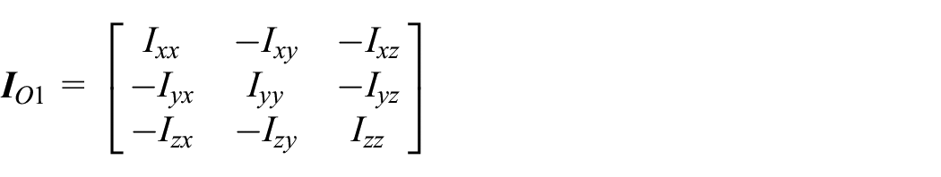
where m0 is the mass of the virtual object, J0x, J0y, J0z are the moment of inertia of the virtual object, ( )x represents the transformation of the vector into a matrix.
The virtual object is the object in a virtual microgravity environment, which is used to simulate a real object in space. The motion law of the virtual object under the action of the astronaut interaction force
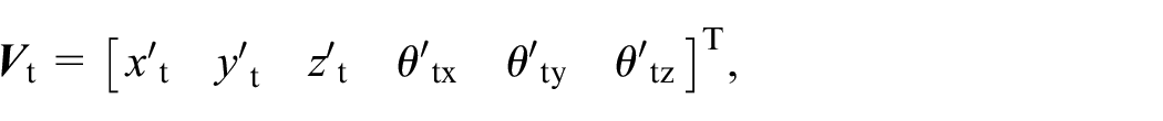
Cable length calculation model
As shown in Figure 1, the origin O of the global coordinate system is fixed on the system frame, and the origin O1 of the local coordinate system is on the geometric center of the end effector. The kinematics equation of the actuator 43 :

where

Cable target length

where
Target angles of cables are 44 :
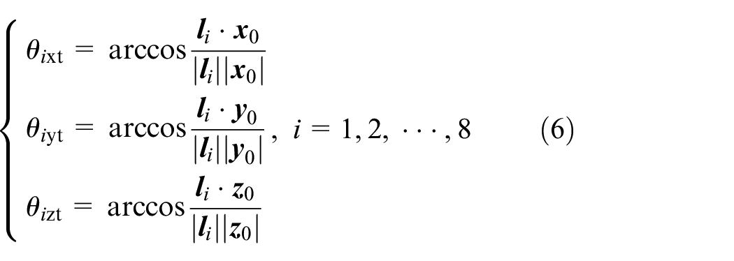
where
When the rotation angle of the end effector is too large, the cable will collide with the end face of the end effector. Figure 3 shows the relationship between the boundary vector of the cable and the end effector. The conditions for the interference between the cable and the end effector are:

where

Boundary vector of the cable and the end effector.
During astronaut training, HIVMTS use equation (7) to monitor whether there is a risk of interference in the next target pose in real-time. If there is a risk of interference, the control system will maintain the instruction at the previous moment until the interference risk is revoked.
Cable tension calculation model
The function of the cable tension control model is to calculate the expected tension F7t and F8t of LF. The parallel cable driven system is a redundant drive system, so the expected tensions of cables are not the only solution. Here, a new cable force distribution strategy is designed to find the optimal solution of the expected tensions. The optimization content is as follows:
(1) Optimization variables
The optimization variables are the expected tension F7t and F8t of LF.
(2) Objective function 8

where

The purpose of this objective function is to make the tension of all cables as close as possible to the expected average tension Favg. Therefore, in the process of astronaut training, the variation range and speed of cable tension are reduced as much as possible to avoid the system stiffness and load changing too fast. Then the stability of the system is improved.
(3) Constraint conditions
Cable elastic expression:

where

the dynamic expression of the actuator 33 :

where


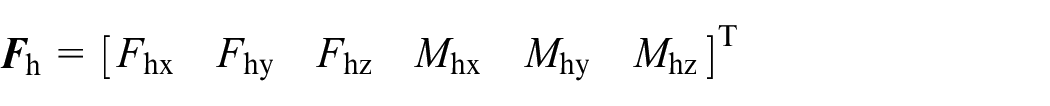
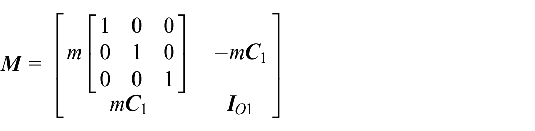


where m is the mass of the end effector,

With reference to the cable traction characteristics and the driving ability of the cable drive unit, 43 the cable tension needs to meet:

where Fmax is the upper limit of the cable tension, Fmin is the lower limit of the cable tension.
According to the cable elasticity equation (equation (9)), the actuator dynamics equation (equation (10)) and the allowable variation range of cable tension (equation (11)), the constraint conditions can be obtained as follows:

(4) Solution of expected tension of the LF
The method of solving the expected tension (F7t and F8t) is to bring the current target pose

The flight speed of the i particle is expressed as:

The individual extreme value of the i particle is:

The global minima of all particles are:

The update equation for the position and velocity of the i particle 45 :

The expected tension solution process of LF is shown in Figure 4.

Solution process of expected tension.
LP control model
Figure 5 is the schematic diagram of the LP control model, G(s) is the cable drive unit. The displacement of the cable is controlled by the active disturbance rejection controller (“ADRC” controller). It has three main parts, including tracking differentiator (TD), extended state observer (ESO) and error feedback controller (NLSEF). The controller can resist external interference without the precise model of the controlled object, so as to achieve higher control accuracy.
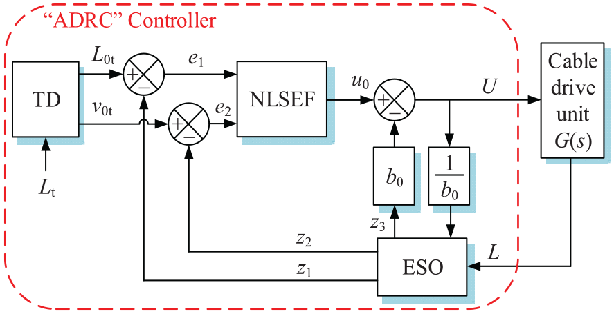
The schematic diagram of LP control model.
Each part of the LP control model is described as follows:
(1) Tracking differentiator (TD)
The tracking differentiator is the transition process of the “ADRC” controller. Its outputs are the cable target length L0t and the cable target speed v0t, which can be expressed as 46 :
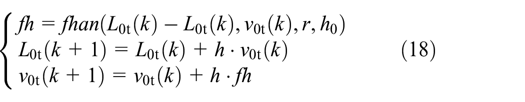
where fh is the synthesis function of the fastest control, h is the step length, h0 is used to prevent the overshoot phenomenon of v0t, r is the tracking speed factor.
(2) Extended state observer (ESO)
The role of ESO is to eliminate system disturbances in real-time. The principle is to expand the observed disturbance into a new state variable and use feedback principle to eliminate the disturbance. The equation for ESO is 47 :

where z1 is the observed cable length, z2 is the observed cable speed, z3 is the observed system disturbance, and L is the actual length of the cable, β01, β02, β03, and b0 are adjustable parameters, fal is a nonlinear function, which can be defined as 47 :

(3) Error feedback controller (NLSEF)
The equation for NLSEF is:

where e1 is the cable length error, e2 is the cable speed error, β1 and β2 are adjustable parameters.
LF control model
As shown in Figure 6, the principle of the LF control model is to use a compliant control method to convert the target tension of cables into the target length of cables, and then use the “ADRC” controller to control the cable length, thereby indirectly controlling the cable tension. This compliance control method is: the spring is connected in series in LF, and then the cable tension is controlled by controlling the spring elongation, and the tension compensation module is introduced to further improve the control accuracy of the spring elongation.

The schematic diagram of LF control model.
The function of the tension compensation module is to reduce the error of the spring elongation caused by the error of the cable elasticity and the mechanical structure. The input of the tension compensation module is the tension error of the LF, and the controller CB(s) is the PD controller. The target length of the cable is calculated using the compliance control method:

The LF control model avoids the problem that the classical force servo control method is sensitive to disturbances, and it has the characteristics of no need to use an accurate parallel cable model, high tension control accuracy, and strong resistance to external disturbances.
Working principle of the training system
The composition of the training system
The overall structure model of HIVMTS is shown in Figure 7. The system consists of the end effector (working object), cables, cable drive units and VR glasses.

Overall structure.
The cable drive unit uses the screw nut mechanism to drive the cable to do the telescopic movement. Compared with the existing disc winding mechanism used in HIVMTS, the screw nut mechanism avoids the transmission error caused by the change of the winding radius of the cable, and there is no return clearance caused by the reducer, which improves the transmission accuracy of the system. 48 The working principle of HIVMTS is to sample the interaction force between the astronaut and the virtual object, and calculate the motion of the virtual object from equation (2) as the input condition of the system. Then we use the all-position type control strategy to control the motion of cables, so that the end effector of the HIVMTS generates the motion law of the virtual object in the microgravity environment.
When performing object handling training in microgravity environment, the astronaut wears VR glasses, holds the handle of the end effector with both hands and pushes it to move. The astronaut will see in VR glasses that he operates an object in a microgravity environment, which is a virtual object. The shape and pose of the virtual object are modeled by computer and displayed in VR glasses. 49 The use of VR technology enhances the sense of presence in microgravity environment training. 50
The model of the cable drive unit
As shown in Figure 8, a cable drive unit includes a motor, a screw nut mechanism, and a guide wheel.

Principle of a cable drive unit.
There are two inputs that affect the output speed V of the motor drive unit. One is the motor drive voltage U, and the other is the external interference force F (cable tension). Therefore, the mathematical model of the motor drive unit is 25 :

M 1(s) and M2(s) are:


where Ks is the transmission ratio of the motor rotor rotation to the nut translation motion, Jm is the comprehensive converted inertia of the motor rotor, and Bm is the comprehensive converted damping of the motor rotor. Cm is the armature torque coefficient, Ce is the back EMF coefficient, Lm is the armature inductance, R is the armature internal resistance.
Experimental analysis
Experimental environment
We use a two-dimensional planar HIVMTS for experimental verification, and the control system uses a HIL semi-physical simulation system. The experimental equipment is shown in Figure 9, the actuator of the experimental system is shown in Figure 10, and the hardware structure parameters are shown in Table 1.

The planar experimental equipment: (a) cable drive unit and (b) actuator.

The structural representation of experiment system.
Structural parameters of the actuator.

As shown in Figure 10, the end effector of the planar experimental system is pulled by four cables, which can achieve 3-DOF motion. LP contains three cables (L1, L2, L3), and LF contains one cable (L4).
Experimental process
In order to evaluate the comprehensive performance of HIVMTS in virtual operation training, a trajectory curve of the astronaut moving the object in microgravity environment is constructed (Figure 10). Description of the trajectory curve:
(1) The virtual object at the initial time is at point A of Figure 10, and the initial velocity is 0. The astronaut pushes the virtual object in the opposite y-direction and stops the virtual object at point B. The virtual object is moved from point A to point B. This stage simulates the situation that the astronaut pushes the object in the vertical direction.
(2) The astronaut pushes the virtual object in the x-direction and stops the virtual object at point C. The virtual object is moved from point B to point C. This stage simulates the situation where the astronaut pushes the object in the horizontal direction.
(3) The astronaut rotates the virtual object counterclockwise. The virtual object is rotated an angle θa around the z-axis at C point. This stage simulates the situation where the astronaut rotates the object around the z-axis.
Then do two groups of experiments. The virtual environment parameters of each group of experiments are shown in Table 2, and the controller parameters are shown in Table 3. The classical “SF” control strategy and “SS” control strategy were compared and analyzed in each group of experiments. These two sets of experiments show the performance of HIVMTS under different virtual mass, inertia and different control strategies. The astronaut operates the virtual object according to the trajectory shown in Figure 11.
Virtual environment parameters.

Controller parameters.

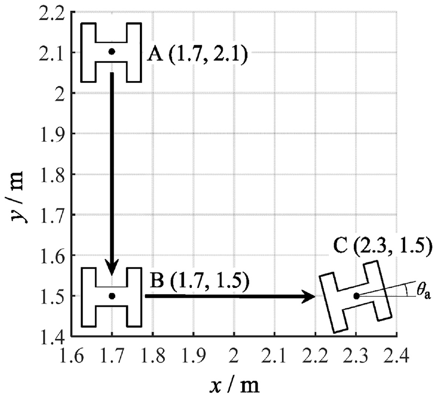
The motion trajectory of the end effector.
Experimental results
In the result graph below, “SFCS” represents “SF” control strategy and “SSCS” represents “SS” control strategy. The astronaut interaction force and interaction torque curves are shown in Figure 12. The cable target tension curves of the group 2 experiment are shown in Figure 13, and the spectrum curves of the cable target tension of the group 2 experiment are shown in Figure 14.

Interaction force and moment curves: (a) the interaction force of the group 1 experiment, (b) the interaction force of the group 2 experiment, (c) the interaction moment of the group 1 experiment, and (d) the interaction moment of the group 2 experiment.

Target tension curves of cables: (a) target tension curves of the No.1 cable, (b) target tension curves of the No.2 cable, (c) target tension curves of the No.3 cable, and (d) target tension curves of the No.4 cable.
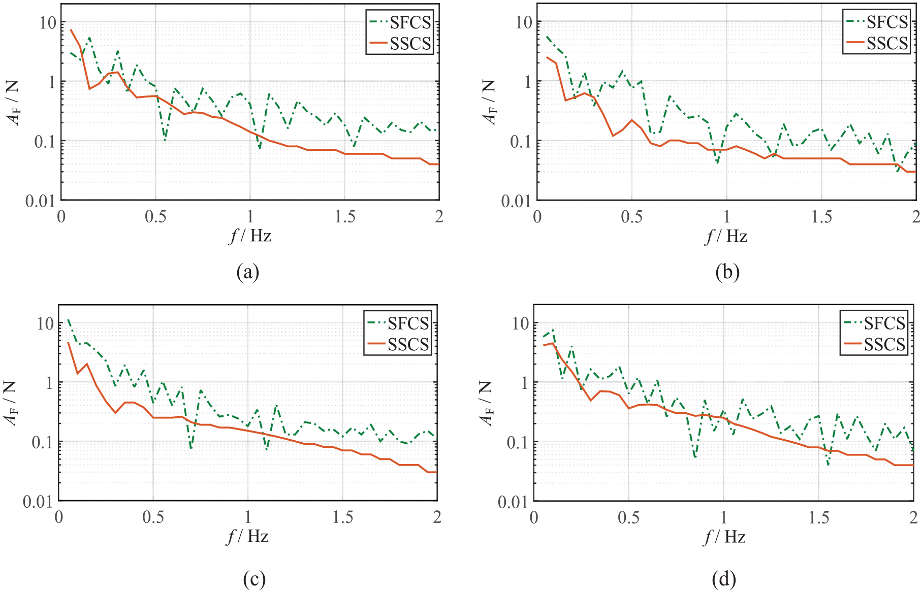
Spectrum curves of the target tension of cables: (a) spectrum curves of the No.1 cable, (b) spectrum curves of the No.2 cable, (c) spectrum curves the No.3 cable, and (d) spectrum curves of the No.4 cable.
The more the middle and high frequency components of the target tension of the cable, the greater the pressure of the force control system, which affects the control accuracy. It can be seen from Figure 13 that the fluctuation of the target tension of the “SS” control strategy is smaller. It can be seen from Figure 14 that the target tension’s amplitude of the “SS” control strategy is relatively small in the medium and high frequency. In order to quantify the target tension fluctuation of different control strategies, we solved the average amplitudes of the target tension in the range of 0.5–2 Hz (Figure 15). The average amplitudes of the target tension can be expressed as:


Comparison of mean amplitudes of medium and high frequency components of target tension.
The tension errors of LF and the speed errors of the end effector are shown in Figure 16. From Figure 16, the maximum tension errors of LF (Table 4) and the maximum speed errors of end-effector (Table 5) can be obtained.
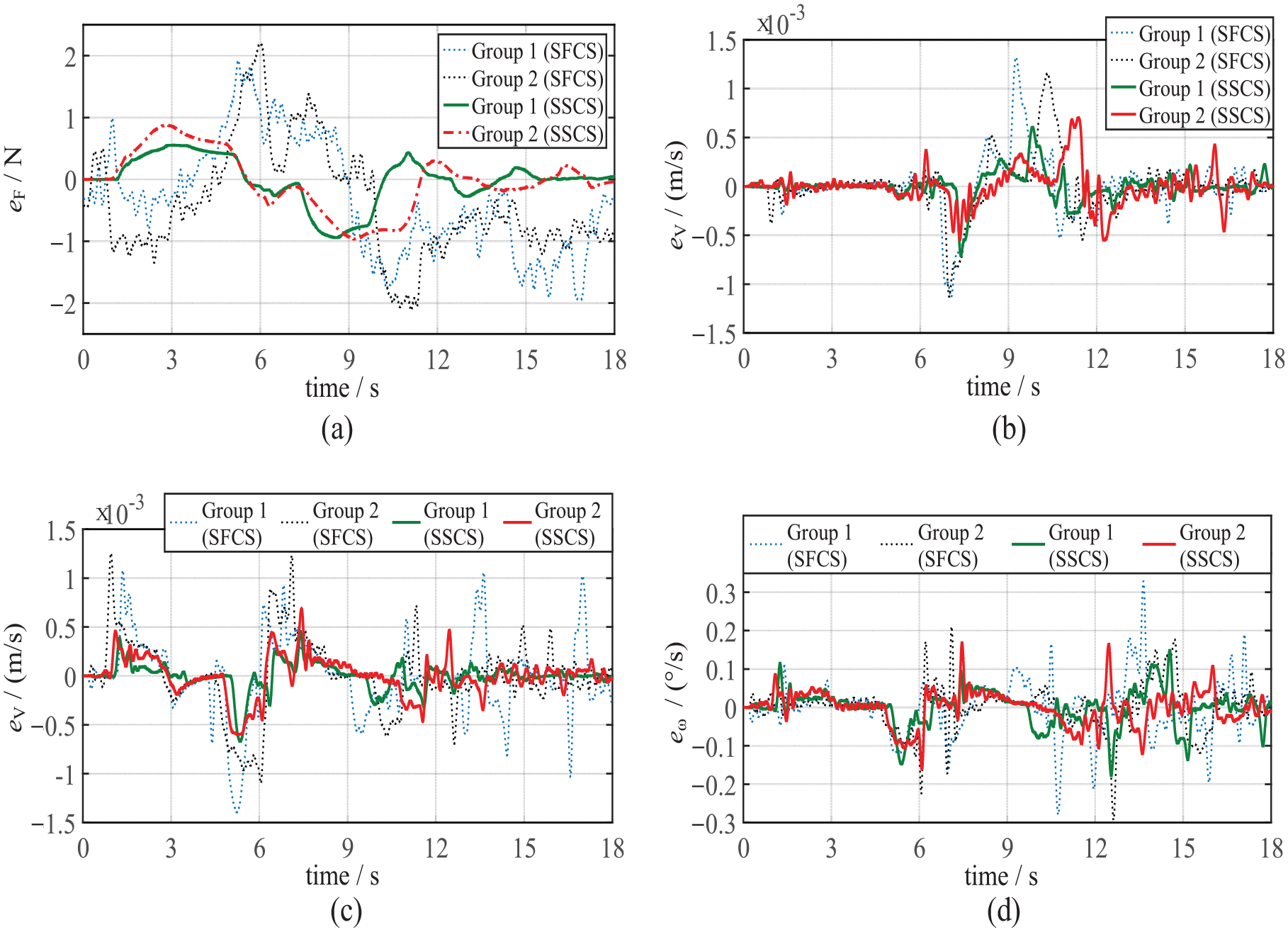
Error curves of LF’s tension and end effector’s speed: (a) error curves of LF’s tension, (b) speed errors of the end effector in x-direction, (c) speed errors of the end effector in y-direction, and (d) angular speed errors of the end effector in rotation direction.
Maximum tension errors of LF.

Maximum speed errors of the end-effector.

In Table 4, the tension error elimination rate
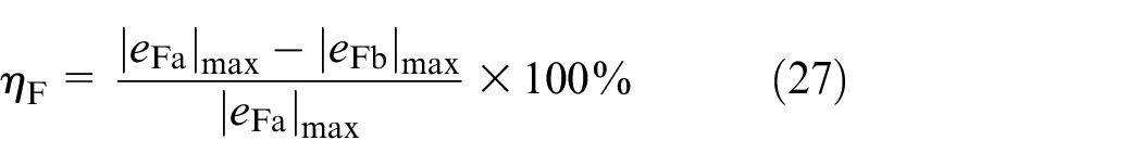
where
In Table 5, the velocity error elimination rate

where
Experimental discussion
Discussion and conclusion of the experimental results:
(1) Compared with the classical “SF” control strategy, the “SS” control strategy can significantly reduce the change rate of the target tension of cables. The high frequency amplitude of the cable target tension is reduced by 44.7%–73.4%. This shows that the newly proposed tension distribution method effectively reduces the change rate of the target tension, reduces the control pressure of the control system, and lays a foundation for improving the control accuracy of the cable tension and the motion control accuracy of the end effector.
(2) The “SS” control strategy improves the tension control accuracy. The tension errors of cables are reduced by 51.6%–57.0%. This shows that the compliance control method and the newly proposed tension distribution method can improve the tension control accuracy.
(3) The “SS” control strategy improves the motion control accuracy. The speed errors of the end effector in the x-direction are reduced by 36.4%–43.4%, the speed errors in the y-direction are reduced by 44.0%–51.4%, and the angular speed errors are reduced by 33.3%–41.4%.
(4) By changing the parameters of the virtual object, the cable tension error only changed by 2.2%, and the speed error of the end effector only changed by 2.9%. This shows that the control accuracy of the system is not affected by the change of virtual object parameters, and the new system is universal. By changing the parameters of the virtual environment, the system can adapt to the operation and training tasks of a variety of objects.
Conclusions
The haptic interactive virtual microgravity training system based on cable-driven (HIVMTS) solves the problems of high costs, short single training time, low safety and difficulty in changing the parameters of the operated object in classical virtual microgravity training methods. The control accuracy affects the tactile sensation of astronauts. However, the existing HIVMTS is faced with the challenge that the control accuracy is difficult to be further improved due to the low accuracy of the transmission mechanism, the large fluctuation of the target tension of cables, the classical force control method is sensitive to disturbance and the uncertainty of the parallel cable model.
In order to solve the problems of HIVMTS, the mechanical structure and control strategy are improved. In terms of mechanical structure, we use the screw nut mechanism to replace the winding mechanism, so as to avoid the transmission error caused by the change of the winding radius of the cable and improve the transmission accuracy. In terms of control, an all-position type control strategy (“SS” control strategy) is proposed to replace the force-position hybrid control strategy (“SF” control strategy).
A planar HIVMTS experimental platform has been established. The experimental results show that compared with the “SF” control strategy, the “SS” control strategy reduces the fluctuation of the target tension of cables and improves the motion control accuracy and tension control accuracy. The control error of HIVMTS is almost unaffected by the change of virtual object parameters. This shows that the improved HIVMTS has better adaptability to the change of virtual training objectives, and provides the possibility to expand the scope of training.
Additionally, there are two limitations to the results obtained in the paper. Firstly, the results were obtained on the experimental equipment with specific specifications. For example, parameters such as frame size and spring stiffness are pre-set. The impact of changes in experimental equipment specifications on experimental results has not been verified yet. Secondly, the actual operated trajectory of the astronaut is complex and random, but the experimental trajectory will not fully cover all possible working trajectory during actual training. When the operated trajectory of the astronaut is extremely complex, the experimental results may not be applicable.
The research content of this paper will provide a better virtual microgravity training environment for astronauts, reduce the discomfort of astronauts in space operation, and provide new ideas for astronauts’ ground training tasks.
In future studies, the collision mechanism and control strategy of objects will be studied, so that the system can simulate the collision form of objects in microgravity environment. The control method of fixed constraint action such as astronaut switch door will be studied, so that the system can train astronauts for more application scenarios.
Footnotes
Handling Editor: Chenhui Liang
Author contributions
Feng Xue: Conceptualization, Methodology, Software, Data Curation, Writing Original Draft. Lixun Zhang: Conceptualization, Resources, Supervision, Writing-Review and Editing, Funding Acquisition. Zhenhan Wang: Formal Analysis, Visualization. Yuhe Fan: Data Curation, Visualization. Da Song: Supervision, Software. Lailu Li: Investigation, Visualization.
Declaration of conflicting interests
The author(s) declared no potential conflicts of interest with respect to the research, authorship, and/or publication of this article.
Funding
The author(s) disclosed receipt of the following financial support for the research, authorship, and/or publication of this article: The research work is supported by “National Natural Science Foundation of China (61773007).”
Ethical approval
This article does not contain any studies with human participants or animals performed by any of the authors.
Informed consent
Informed consent was obtained from all individual participants included in the study.
Data availability
The data that support the findings of this study are available on request from the corresponding author, upon reasonable request.