
Abstract
Automotive engine mounts have recently begun using active elements, while prior studies did not account for the actual engine mounting position. The placement and orientation of real automobile engine mounts are considered when modeling, analyzing, and controlling a source structure with an active mounting system. A piezoelectric stack actuator connected in series with an elastomeric mount composes an active mount. When harmonic excitation forces are used, the secondary force required for each active mount is mathematically determined, and the control signal may reduce the vibration by interfering with the input signal. Additionally, the dynamic relationship of the source structure with a variable parameter may be used to reduce horizontal vibrations. Several simulation findings show that these multidirectional (vertical and horizontal) active mounts may minimize excitation vibrations. Additionally, a simulation was performed to reduce vibrations when a complex signal and noise were present. This was achieved by monitoring the system response using the normalized least mean squares (NLMS) algorithm, an adaptive filter. The control performance degrades as noisy and complicated signals are generated; however, the mitigation trend is the same according to simulations utilizing adaptive filters.
Keywords
Introduction
Background
Most mechanical devices generate noise and vibrations during operation, reducing the dependability and durability of the equipment. Given the present rapid rise in technology, the performance satisfaction of the product and the emotional pleasure that may be experienced via the five human senses must be satisfied. For example, durability, fuel efficiency, and crash performance were considered essential during the earlier development stages of cars, which is an emotional product. However, more recently, consumers have demanded ride comfort and noise vibration harshness (NVH) performance. Owing to the advancement of electric vehicles, the noise and vibration of vehicles must be controlled, a task that has become challenging owing to the excitation force that emerges in the motor, gearbox, and inverter, as opposed to the excitation force that emerges in the internal combustion engine. The research and design of engine mounts, as described in Figure 1, that support the vehicle’s powertrain and insulate the car from the vibrations transmitted by the powertrain are crucial for this reason. The engine mounts allow for the influence of additional components, including the powertrain, sub-frame, and body, on the engine excitation force. Moreover, it generates commotion traveling through the structure, which can result in significant inconvenience for the operator. The majority of commercial cars currently on the road use passive engine mounting solutions that effectively isolate vibrations at low frequencies, but fall short at high frequencies. Also, there are limitations to the passive mounts for minimizing noise, vibration, and harshness (NVH) under a variety of operating conditions, since their attenuation performance is fixed based on the property of passive mounts. Therefore, active engine mounting technology based on smart structures that can enhance ride quality and noise, vibration, and harshness (NVH) performance in variable environments by modifying mount dynamics to suit the low- or high-frequency range, is attracting considerable attention as a key technology in automobile development research. Extensive research and development have been devoted to the creation of an active engine mounting system utilizing smart materials, including piezo elements, magnetorheological (MR) fluids, and shape memory alloys, in order to circumvent these constraints. Currently, active mounting systems are the subject of a number of ongoing investigations. The efficacy of active vibration control utilizing an active mounting system is exceptional. Nonetheless, the substantial expense linked to regulating the physical actuator poses a barrier to its widespread commercialization.

(a) Automotive engine vibrations and (b) mounting system.
Literature review
An engine mount supports the vehicle’s drivetrain and prevents vibrations from being transferred to the body of the car. Rubber, a viscoelastic material, is often utilized; however, it has the drawbacks of being able to insulate only at low frequencies and being unable to regulate vibrations at higher frequencies. The automotive industry has recently considerably invested in the development of electric cars, and consequently, several studies have been conducted to regulate the more complicated external forces produced by motors and gearboxes than those from the present internal combustion engines. The concepts and restrictions of passive, semi-active, and active mounts have been succinctly described by Yu et al. 1 Examples of passive mounts that effectively control vibrations in the low-frequency range, but have limitations owing to their inability to control vibrations in the high-frequency range, are elastic and manual hydraulic mounts. Semi-active mounts commonly use electro-rheological (ER) and magnetic-rheological (MR) fluid mounts that perform better than passive mounts in controlling vibrations in the low-frequency range but fall short in the high-frequency range. To couple an actuator with an existing passive mount, further comparable active mounts such as active elastic and active hydraulic mounts are used. By modifying the dynamic stiffness via the actuator in accordance with each band, vibrations can be managed in both the high- and low-frequency bands.
Choi and Choi 2 designed a sliding mode controller (SMC) and compared the vibration reduction efficacy of shear-mode-type ER fluid engine mounts. Employing an SMC with a variable-changing electric field to the input current resulted in a lower vibration response compared with the scenario where a constant electric field was provided. A perfect engine mount could be created by adopting the hypothesis proposed by Sarkar et al. 3 Regulating the dynamic stiffness of the MR fluid using magnetic field control to stop the flow of the MR fluid lowers the vibration across all frequency ranges. However, when utilized as an engine mount, regulating the fluid is exceedingly challenging and an issue of fluid leakage exists. Chang et al. improved the dynamic vibration absorber (DVA) approach by adding the quasi-zero-stiffness (QZS) method to regulate the anti-resonance created at an ultralow frequency (2.3 Hz) that was intractable by DVAs. 4 Using an active mount that connects a piezoelectric (PZT) stack actuator and rubber mount in series, Liette et al. demonstrated vehicle vibration and noise reduction capabilities in the frequency range of the power electric (PE) of a hybrid vehicle. 5 Additionally, Hong and Kim conducted analytical research on a mounting system employing one active mount and two rubber mounts combining a PZT stack actuator and rubber mount on a vehicle model with a plate structure, and the study successfully demonstrated the system’s applicability. 6
By changing the position of the PZT stack actuator in the plate structure model, Qiu et al. demonstrated the effectiveness of vibration reduction and presented criteria for placing the active mount to minimize the vibration. 7 This could be the best way to fix the mounting system’s current issues of fluid leakage and uncontrollability in the high-frequency range. It may also benefit from the low power and quick response features of the PZT. The controller is another crucial factor to consider when using active engine mounts (AEMs). The Fx-LMS technique, an adaptive filter, was used by Hausberg et al. to forecast the dynamic properties of AEM after theoretically and empirically examining the secondary path modification in AEM. 8 Kraus et al. experimentally used an actuator and a viscoelastic mount to create an engine mount for a vehicle. The experiment demonstrated that vibration and noise were minimized by controlling the actuator input value by passing the mass response through the Fx-LMS algorithm. 9
Problem statement
Numerous forms of smart materials are being offered for the vibration insulation of a vehicle body by the vehicle engine, as shown by numerous studies of interest. A semi-active mounting system employing ER and MR fluids, a smart structure-based engine mounting system used for vibration isolation, has trouble regulating vibrations over a broad frequency range owing to the nature of the fluid and has the risk of fluid leakage. To address this issue, a viscoelastic substance, rubber, was combined with a PZT actuator in an active mounting system. Additionally, the use of an adaptive filter as the actuator’s input signal and as a signal to monitor the system’s response signal to reduce vibrations was suggested. A technique exists for altering the structure when a single frequency is excited or a narrowband vibration reduction is targeted; however, this is not applicable to an electric car because the complex signals produced by the gearbox, transmission, and motor are stimulated in such a way that they cause these signals to be complex. Because the vehicle engine mounts were combined in both the vertical and horizontal directions, the source–path–receiver structure used in this study was accordingly designed. Figure 2 shows the vibration reduction observed using the PZT stack actuator and active mount coupled with rubber.

Active vibration control system applied to automotive mounts.
The remainder of this paper is structured as follows. Section 2 suggests that to reduce vibration, active mounts are merged in the vertical and horizontal directions in the two-dimensional seven-degree-of-freedom model. Section 3 suggests that when the structure is activated by a single sinusoid, the analytically computed input value for each route is used to compare the abatement performances. Section 4 specifies that when complex signals such as amplitude and frequency modulated (AM and FM) signals are stimulated, the performance reduction is compared between the case in which the analytically computed input signal is applied to the secondary route and the case in which the response signal of the system is monitored by the NLMS algorithm. Section 5 concludes the paper by summarizing the findings and outlining possible future research options.
Multi-directional active mounting systems
Lumped parameter modeling
Figure 3 depicts the subframe construction, AEM, and engine of the vehicle. The subframe is designated as the receiver and the rubber-coupled active mount and piezo stack actuator as routes. The receiver was created as a straightforward two-dimensional construction whereas the source was developed as a curved two-dimensional structure because the engine mount in the real vehicle was attached horizontally to the engine and subframe.
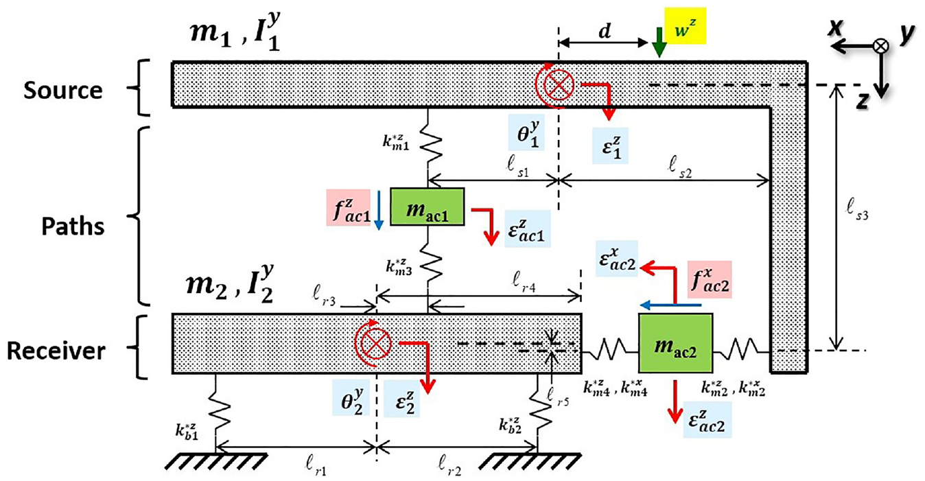
Modeling diagram with complex stiffness.
The source mass is represented by

Here,

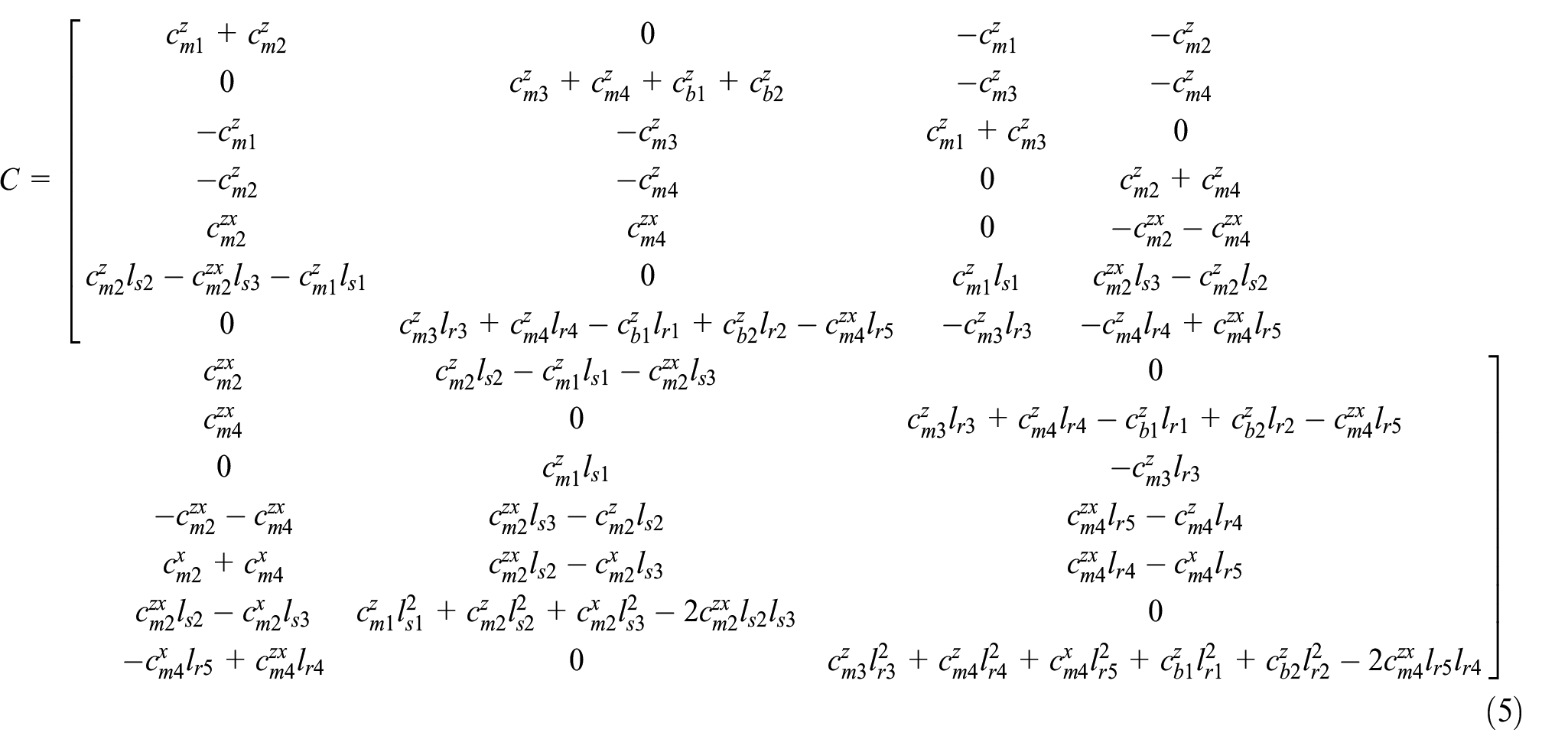
Real-valued stiffness and damping are determined using the aforementioned equation. Consequently, equations (3)–(8) depict the mass matrix, stiffness matrix, damping matrix, displacement vector, excitation force vector, and control force vector when stated as the Kelvin–Voigt model, as shown in Figure 4.


Mathematical modeling using a Kelvin–Voigt expression.
To examine the displacement of the location adjacent to the mount, the model built using the coordinates of the center of gravity was transformed into mount coordinates.
In Figure 5,


7-DOF modeling diagram on mount coordinates.
According to this transformation matrix, the displacement vector of the mount coordinates can be derived as shown in equation (11). Equation (12) converts the equation of motion into mount coordinates by multiplying the transformation matrix with the stiffness, damping, and mass matrices of the CG coordinates.


The efficacy of vibration reduction of the active mount can be examined by converting this equation of motion into mount coordinates.
Estimation of horizontal displacement
The proposed lumped parameter model makes it possible to retrieve the vertical direction response at each location, but not the horizontal direction response. Therefore, the horizontal direction response trend of each position was calculated in this study using the dynamic relationship of the structure, and the position adjacent to the horizontal mount that significantly impacted the horizontal direction displacement, was identified. Figure 6 depicts the dynamic movement of the source structure.
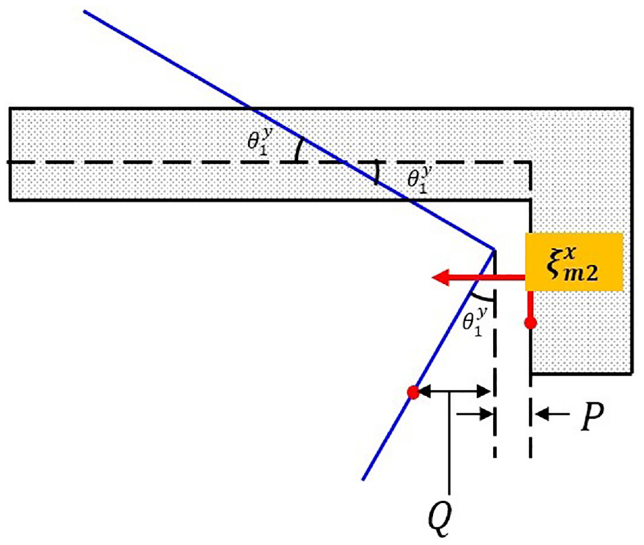
Dynamic movement of the source by an external force.
The equilibrium condition of the source is indicated by the dotted line in the Figure 6, whereas the movement of the source as a result of an external force is indicated by the solid line. The displacement of the source near the horizontal mount can be calculated by adding P and Q, where P can be calculated using the trigonometric formula in equation (13), the properties of an isosceles triangle, and the ratio of similitude, and Q can be calculated using equation (14).


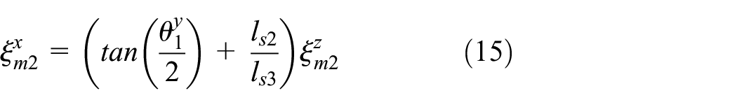
Equation (15) describes the displacement trend of the source adjacent to the horizontal mount, based on equations (13) and (14).
Equation (16) is obtained by linearizing equation (15).

The form of the structure, rotational angle of the source, and vertical displacement have an impact on the horizontal displacement of the source, as can be seen from the aforementioned equation. Because the structure of the source cannot be easily altered, the vertical displacement may be used to regulate the horizontal displacement of the source. Figure 7 shows the dynamic movement of the receiver structure.
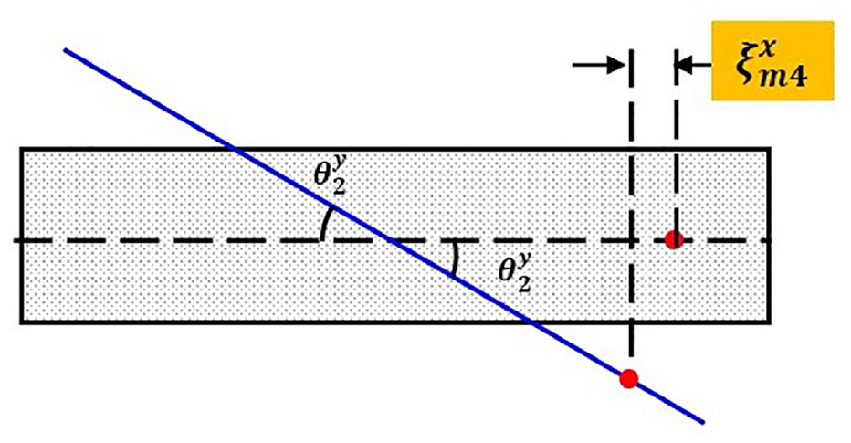
Dynamic movement of the receiver by an external force.
Figure 7 shows the equilibrium condition of the receiver as a dotted line and the movement of the receiver as a result of an external force as a solid line. In the process of determining the horizontal displacement of the source using the properties of an isosceles triangle and the formula for a trigonometric function, the displacement of the receiver adjacent to the horizontal mount is defined as

Equation (18) is obtained by linearizing equation (17).
This equation demonstrates the effects of the rotation angle and vertical displacement of the receiver on the horizontal displacement. Consequently, this can be managed by moving the receiver horizontally. This allowed the investigation of the reaction of the 7-DOF model in the vertical and horizontal directions.
Quantification of control input
When a harmonic force is applied to a structure, both the amplitude and phase significantly impact the reaction. Euler’s law can also be used to represent the excitation and control forces in complex numbers, as shown in equations (19)–(21).


The vertical displacement of the i-th position of the mount coordinates that is a response influenced by the excitation and control forces supplied via the secondary route, is represented by expression


Equation (25) that calculates the displacement of each location of the mount coordinates using the compliance matrix, can be used to achieve this.

Equation (25) confirms that the response can be expressed using the compliance matrix, excitation force, and control force, implying that the motion of each position can be expressed using the amplitude of the excitation force, the amplitude of the control force, and the phase. The displacement of each position is defined by equation (26).
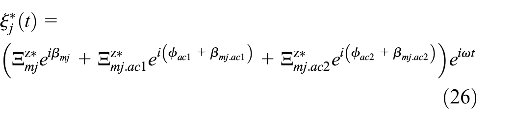
The displacement responses at position j have an amplitude


Thus, everything is known, with the exception of the amplitude and phase of the vertical and horizontal mount control forces, from equation (25), indicating the displacement. Equation (31) describes the phase of the control force that equalizes the phase values and is used to presume that the displacement will be zero.

Equation (32) expresses the phases that the vertical and horizontal mounts should have in relation to each other.

Equation (33) can be obtained by substituting equation (32) into equation (25).

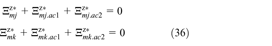
The amplitudes of the vertical and horizontal mounts are determined by adding an equation that similarly makes the displacement zero at point k, because the two unknowns cannot be determined using only equation (33). Equations (34) and (35) express secondary path inputs.


Equation (36) represents the arrangement of the equations to obtain the amplitudes of the vertical and horizontal mounts that make the amplitudes of equations (33) and (35) zero.
Equation (37) is obtained from equation (36) that transposes the element caused by the stimulating force to the right side by inserting equations (27) and (28) and converting it into a matrix form.
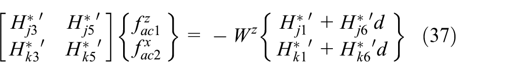
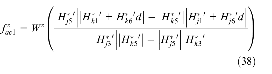
The amplitudes required for vertical and horizontal mounts can be obtained from equations (38) and (39) by multiplying the inverse matrix of the matrix in equation (37) that contains only the compliance components between the left sides.

Thus, the control force with the phase value of equation (32) and amplitude values of equations (38) and (39) is input to the secondary path to control the displacement of position j to zero, and the control force with the phase value of equation (34) and amplitude values of equations (38) and (39) is input to the secondary path to control the displacement of position k to zero.
Validation with numerical simulation
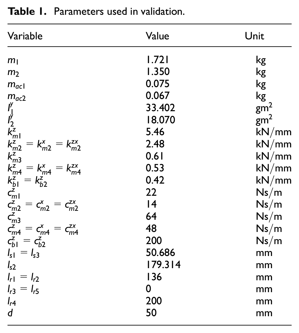
A computer simulation was performed to verify the performance prior to conducting an experiment to demonstrate the model and aforementioned derivation formula. The simulation parameters are listed in Table 1.
Parameters used in validation.
Vertical and horizontal mounts were positioned at the CG of the source and receiver, respectively, and the simulation was performed using the computed input value for the second pathway. The response was examined using the linear time-invariant state-space approach, and the effectiveness of the vibration reduction was assessed by comparing the responses produced when the excitation force alone and the computed control input were applied. Equations (40)–(42) that use the mass-damping-spring motion equation transformed to the mount coordinates of equation (12), define the state-space equation.


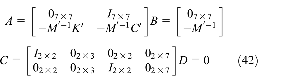
In equation (42), Matrix A represents the system’s state, Matrix B represents its input, Matrix C represents its output, and Matrix D represents its direct transfer term. Matrix D is a zero matrix, in this case, because of the lack of directly transferred components. By suitably modifying the state variable represented by equation (43), the simulation results were expressed as the displacement of the location adjacent to the mount.

To easily understand the state–space method, a block diagram is shown in Figure 8.

Block diagram for the state-space representation.
Control through quantified input
The excitation frequency was set to 400 Hz, excitation amplitude to a sinusoidal signal with a 10 N amplitude, and sampling frequency to 15,000 Hz for the computed secondary route input simulation. Figure 9 displays each displacement response before the predicted secondary path input was added to the 7-DOF model and only the excitation force was applied.

Response for the harmonic excitation force.
In Figure 9,
In Figure 10, position 1 is the response of

Position definition for the vibration measurement.

Controlled responses (Path 1, Path 2 from the left).
Comparison of RMS values.
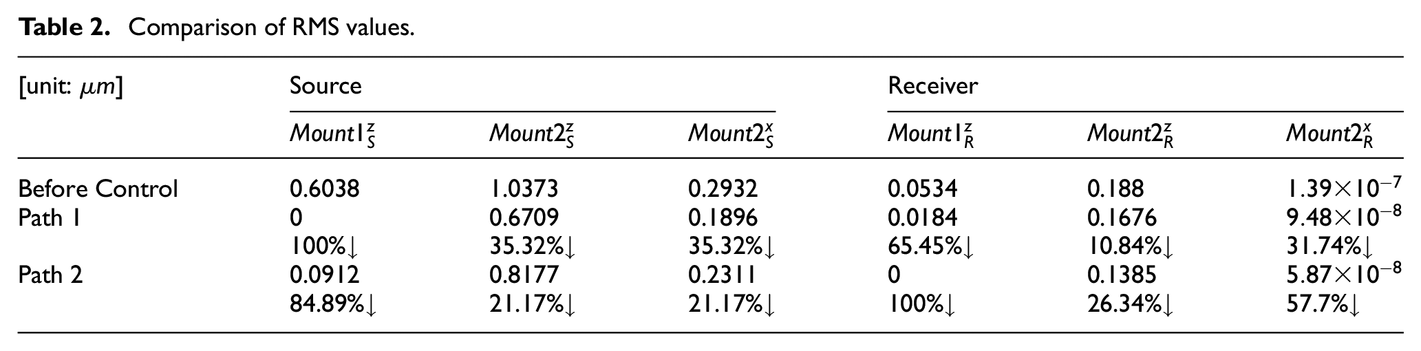
The vibration at the target point as well as at other points was alleviated. This improved the NVH performance of the vehicle and the stability of the engine by reducing the vibration of the engine and subframe. The simulation results presented above demonstrated that horizontal active mounts required more control than vertical active mounts.
Control through NLMS algorithm
In the case of controlling with the calculated secondary path input, a problem exists in that the control force must be newly calculated when the excitation force is changed and when an external force generated owing to a change in the external environment is applied. To solve this problem, it should be controlled using an adaptive filter that changes the filter coefficients according to the conditions. Vibrations can be controlled using least-mean-square (LMS) algorithms, which are representative adaptive filter algorithms. The LMS algorithm is a simple and robust algorithm that is widely used to reduce vibration and noise. However, the convergence characteristics of the filter coefficients are significantly influenced by the initial values, and the convergence speed is relatively slow. In addition, Adaptive filters are extremely reference signal dependent. Reference signals ought to incorporate frequency components of vibration, the precise identification of which is typically challenging. In the event of any inconsistencies, the filter’s efficacy is significantly compromised, while this fact does not apply since this work is only checking for feasibility. Therefore, in this study, a normalized LMS (NLMS) algorithm, which compensates for the disadvantages of the LMS algorithm, was used, along with a method of controlling the vibration in real time by tracking the response of the source, which is the largest signal among the responses of the sensor. Before testing this method, a computer simulation was performed to determine the feasibility of implementation. Figure 12 shows a schematic of the 7-DOF NLMS control simulation.

Simulation schematic for NLMS control.
The vertical signal at position 2 was converted into a horizontal signal by substituting the dynamic relational expression and was applied as the horizontal mount input force. For the NLMS control simulation, three simulations were performed by inputting a simple sinusoidal signal, an amplitude modulation signal (AM signal), and a frequency modulation signal (FM signal) as the excitation forces. In all the three simulations, the sampling frequency was set to 15 kHz. As the input of the simulation for the case where the excitation force was a simple sinusoidal signal, a sinusoidal signal with an amplitude of 10 N and an excitation frequency of 400 Hz and white noise were given, as shown in equation (44).

In the case of excitation with a sine wave, the simulation results are shown in the responses of Figures 13 and 14, the time-domain steady-state response RMS value comparison before and after control in Table 3, and the FRF RMS value comparison in Table 4.

Time-domain signal of source parts without and with NLMS control (sinusoid): (a) position 1, (b) position 2, and (c) position 3.

Time-domain signal of receiver parts without and with NLMS control (sinusoid): (a) position 4 and (b) position 5.
Comparison of time-domain RMS values (sinusoid).

Comparison of frequency-domain RMS values (sinusoid).

The time-domain RMS results, as presented in Table 3, showed that the vibrations tended to be reduced by 78.73% for
As shown in the time domain,
Owing to the development of electric vehicles, the powertrain of a vehicle generates complex signals of at least two to three frequencies. This indicates that achieving control is difficult by calculating the secondary path input or simply using the NLMS algorithm. Therefore, when AM and FM signals with multiple frequencies are excited, the multi-NLMS algorithm with multiple channels is used as a control; a schematic of the multi-NLMS algorithm is shown in Figure 15.

Schematic for the multi-NLMS algorithm.
In the multi-NLMS algorithm, when an input
The simulation input for the case where the excitation force was an AM signal was given as an AM signal with three frequency components and a carrier frequency of 20 Hz, as shown in equation (45).

For each NLMS input, the frequency components of equation (45) are entered, as shown in equations (46)–(48).


The generated signals were added and applied to the input of the secondary path through appropriate gain and phase controls. Unlike sinusoidal signals, comparing the responses of AM and FM signals in the time domain is difficult; therefore, they were compared using frequency response graphs (FRFs) through FFT. When the excitation force is an AM signal, the multi-NLMS control results are shown in the FRFs in Figures 16 and 17. In addition, at each position, the RMS responses from 4 s to 4.05 s in the time domain before and after control were compared, as presented in Table 5, and the RMS responses in the frequency domain from 300 Hz to 500 Hz were compared, as presented in Table 6, to identify the reduction performance.

Frequency response functions of source parts without and with NLMS control (AM signal): (a) position 1, (b) position 2, and (c) position 3.
Frequency response functions of source parts without and with NLMS control (AM signal): (a) position 4 and (b) position 5.
Comparison of time-domain RMS values (AM signal).

Comparison of frequency-domain RMS values (AM signal).

The time-domain RMS results, as presented in Table 5, showed that the vibration tended to be reduced by 58.6% for
The simulation input for the case where the excitation force was an FM signal was given as an FM signal with three frequency components and a carrier frequency of 20 Hz, as shown in equation (49).

For each NLMS input, the frequency components of equation (49) are entered, as shown in equations (50)–(52).


The generated signals were added and applied to the input of the secondary path through appropriate gain and phase controls. When the excitation force is an FM signal, the multi-NLMS control results are shown as the frequency response results in Figures 18 and 19. In addition, at each position, the RMS responses from 4 s to 4.05 s in the time domain before and after control were compared, as presented in Table 7, and the RMS responses in the frequency domain from 300 Hz to 500 Hz were compared, as presented in Table 8, to determine the reduction performance.

Frequency response functions of source parts without and with NLMS control (FM signal): (a) position 1, (b) position 2, and (c) position 3.

Frequency response functions of source parts without and with NLMS control (FM signal): (a) position 4 and (b) position 5.
Comparison of time-domain RMS values (FM signal).

Comparison of frequency-domain RMS values (FM signal).

The time-domain RMS results, as presented in Table 7, showed that the vibrations tended to be reduced by 56.48% for
Conclusion
In this study, a piezo actuator and rubber were used to construct an engine mount that connected the engine to the vehicle subframe. The vibration reduction performance was determined by arranging it in the direction of a real engine mount connection. The overall structure was developed as a source–path–receiver and simulated using a vehicle engine as the source, an active mount as the path, and a subframe as the receiver. The vibration reduction effect was confirmed by determining the amplitude and phase required for each active mount for a sinusoidal signal. The NLMS algorithm, which is an adaptive filter, was used to confirm the vibration reduction effect for the excited AM and FM signals with three frequency components.
Using vertical and horizontal active mounts and 7-DOF modeling, the ability of the structure to reduce vibrations was examined. A method to regulate the reaction in the horizontal direction was sought after the dynamic relational representation of this study enabled us to understand the trend. When a sine wave was stimulated and the control force of each active mount was determined, the vibration reduction impact was summarized. The vibration reduction effect was further confirmed using the NLMS algorithm when complicated and noisy signals were stimulated. Consequently, the vibration of the source at a location near its CG and the vibration of the receiver tended to be significantly reduced, enhancing the NVH performance.
Experiments should be conducted in future studies to validate each simulation. To allow for more effective control, we will also demonstrate the impact of the coupling orientation of the engine mount on the source and receiver. Also, other control algorithms can be applied and compared to determine which algorithm is suitable for a variety of conditions. The efficacy of active vibration control utilizing an active mounting system is exceptional. Nonetheless, the substantial expense linked to regulating the physical motor poses a barrier to its widespread commercialization. Better vibration control cannot be anticipated, despite the use of active mounts, due to the fact that vehicle mounting locations are typically designed without NVH performance in mind (as illustrated in Figure 1). Determining the ideal placement of the active mounting system is therefore essential for minimizing the expense of the control.
Footnotes
Handling Editor: Chenhui Liang
Author contributions
Conceptualization: B.K.; methodology: D.H.; software: H.M.; writing—original draft preparation: D.H.; writing—review and editing: D.H. and B.K.
Declaration of conflicting interests
The author(s) declared no potential conflicts of interest with respect to the research, authorship, and/or publication of this article.
Funding
The author(s) disclosed receipt of the following financial support for the research, authorship, and/or publication of this article: This work was supported by the 2022 Yeungnam University Research Grant (222A380002) and by Basic Science Research Program through the National Research Foundation of Korea (NRF) funded by the Ministry of Education (NRF-2022R1F1A1076089).
Data availability statement
Data presented in this study are available upon request from the corresponding author. These data are not publicly available because of the large sample size.