
Abstract
Based on the working conditions of the variable center distance non-circular gear pair, this research provides the rounding theories and methods for the theoretical pitch curves of the gear pair, including establish the working conditions model of the variable center distance non-circular gear pair; group and classify the instantaneous working conditions and the instantaneous meshing arcs; design rounding algorithms for instantaneous meshing arc group category 1, 2, and 3; and propose the dynamic allocation strategy for distribute the total rounding amount on each pair of instantaneous meshing arcs. Finally, with the help of a variable center distance non-circular gear pair example, this research successfully proved the correctness and effectiveness of the above rounding theory and method, achieve the goal of rounding the theoretical pitch curves of the variable center distance non-circular gear pair.
Introduction
According to the meshing theory, in order to mesh properly each pair of gear driver can and must only have integer number of teeth arranged on both driving and driven gear’s pitch curves.1,2
During the design process of the cylindrical gear, to make sure the length of the driving and driven gear’s pitch curves can be divisible by standard pitch, typically, the center distance of the cylindrical gear pair can be calculated by the module of the gear pair and the teeth number of the driving gear and the driven gear, after that the pitch curves of the driving gear and the driven gear can be calculated by the center distance mentioned above, and then the transmission ratio calculated by the teeth number of the driving gear and the driven gear. Clearly, these pitch curves can be divided evenly by standard pitch.3–5
For non-circular gear pair, due to its changing transmission ratio during meshing, it is impossible to calculate the center distance of the gear pair by the module and the teeth number of the driving gear and the driven gear just like cylindrical gear. As a result, the theoretical pitch curves of the driving gear and the driven gear calculated by known conditions cannot be evenly divided by standard pitch in most cases. To address this issue, Xutang and Guihai suggest that designers should dynamically adjust the known conditions, such as the parameters that control the base curve used to fit the gear pair’s pitch curves, and the modulus that directly related to the pitch, until the pitch curve length for both driving gear and driven gear are multiple of the standard pitch. 6
Under the condition of transmission ratio unknown, based on the aforementioned ideas, by adjusting the parameters in the base curves such as eccentric circular curves,7–12 higher-order elliptical curves,13–19 Pascal’s limaçon,20,21 Hermite cubic parameter curves, 22 epitrochoids, 23 Aronhold’s first principle regression curve,24,25 etc., it is possible to design non-circular gear pair’s pitch curves which can be divisible by the pitch. 26
Under the condition of transmission ratio known, by scaling the theoretical pitch curve proportionally, at the expense of changing the center distance of the gear pair 27 ; or adjusting the gear modulus, at the expense of increasing the gear pair’s design and manufacturing costs dramatically, it is also possible to design pitch curves which can be divisible by the pitch and meshes same as the known transmission ratio.
However, the variable center distance non-circular gear pairs not only have variable transmission ratio but also have center distance during the meshing process, and they have one-to-one mapping relationship with the pitch curves of the gear pair,28–30 which making it difficult to ensure the designed theoretical pitch curves can be evenly divided by the pitch through method mentioned above without adjusting the gear modulus, and that will highly increasing the design and manufacturing costs.
To address the aforementioned issues, after the research and analysis of the variable center distance non-circular gear pair’s meshing process, the theoretical center distance curve


By combining the center distance curve, the transmission ratio curve, and the instantaneous meshing pole radius of the pitch curves of the driving gear and the driven gear, the working conditions model of the variable center distance non-circular gear pair can be established. Then, according to the grouping and classification method provided in this paper, the instantaneous meshing arcs in this model can be grouped and classified into four categories.
Based on the general meshing model of the instantaneous meshing arc pair establishes at the micro-level, this research provides rounding algorithms for instantaneous meshing arc group category 1, 2, and 3. After that, propose a dynamic allocation strategy for the total rounding amount at the macro level. Finally, the rounding theory and method for the pitch curves of variable center distance non-circular gear pair based on working conditions have been developed. And an example of variable center distance non-circular gear pair is provided to validate the correctness and effectiveness of these rounding theory and method.
Theory and method of pitch curve rounding for variable center distance non-circular gear pair based on working conditions
The theory and method of pitch curve rounding for variable center distance non-circular gear pair based on working conditions described in this section can be divided into four main parts as shown in Figures 3 to 6.
The working conditions model of the variable center distance non-circular gear pair.

The classification and analysis of the instantaneous meshing arcs in the working conditions model.
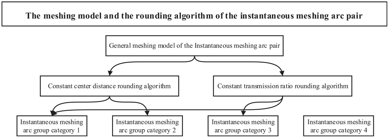
The meshing model and the rounding algorithm of the instantaneous meshing arc pair.
Dynamic allocation strategy of rounding amount.
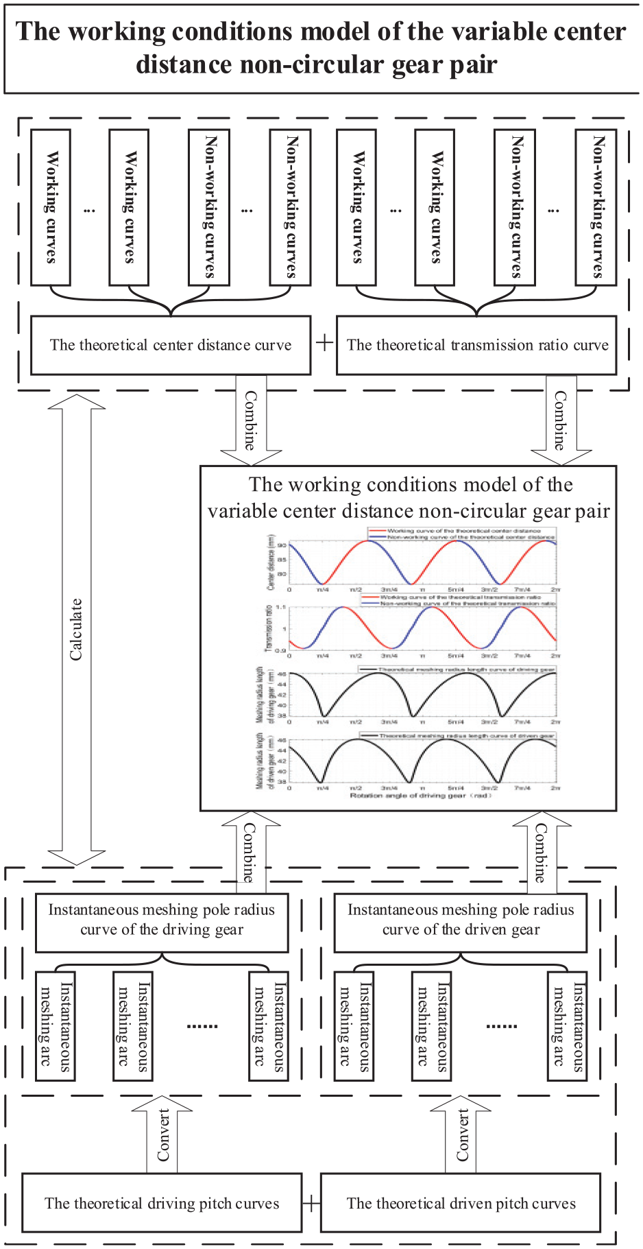
As shown in Figure 3, the working conditions model of the variable center distance non-circular gear pair will be built in the first part of this research. The model is a coordinate system group, which takes the driving gear’s rotation angle as the abscissa, and respectively takes the instantaneous center distance, the instantaneous transmission ratio, and the length of the instantaneous meshing pole radius of the pitch curves of the driving gear and the driven gear as the ordinate. Based on the one-to-one relationship between the center distance curve, the transmission ratio curve and the theoretical pitch curves of the driving gear and the driven gear of the variable center distance non-circular gear pair, all of the center distance curve, the transmission ratio curve, and the curves made by the instantaneous meshing pole radius length of the theoretical pitch curves of the driving gear and the driven gear can be calculated and drawn on this coordinate system group.
As shown in Figure 4, the second part of this research is mainly focus on the classification and analysis of the instantaneous meshing arcs based on the above-mentioned model. In this part, the instantaneous meshing arcs that mesh at the instants associated with the current instant will be classified into same instantaneous meshing arc group. Then, according to the categories of the instantaneous working conditions connected with the instantaneous meshing arcs through the meshing instants, the geometric shape of instantaneous meshing arcs, and the rounding feasibility and rounding algorithm adaptability of the instantaneous meshing arcs in each instantaneous meshing arc group, these groups will be analyzed and classified into four categories in this part of the research.
As shown in Figure 5, the third part of this research will establish and analysis the general meshing model of any instantaneous meshing arc pair at the micro level. And propose the constant center distance rounding algorithm and the constant transmission rounding algorithm for instantaneous meshing arcs in instantaneous meshing arcs group category 1, 2, and 3.
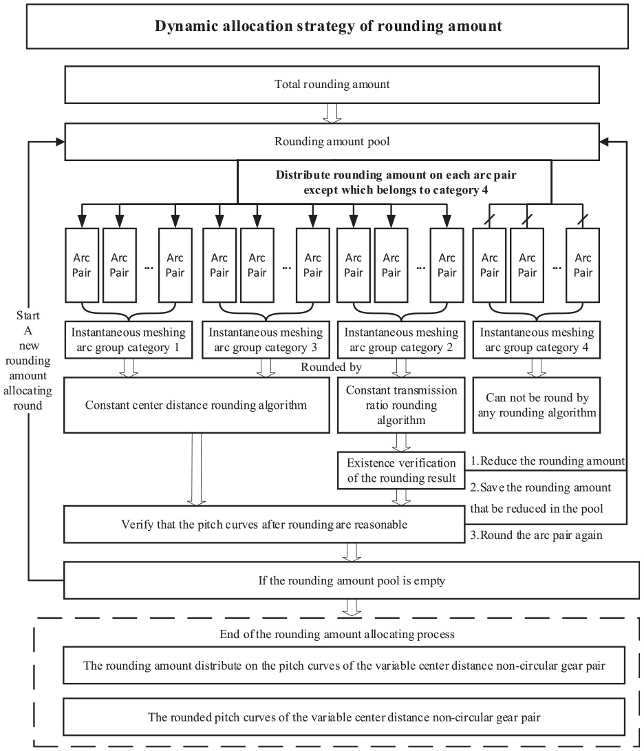
As shown in Figure 6, the dynamic allocation strategy for rounding amount at the macro level will be proposed in the fourth part of this research which contain several rounding amount allocating rounds. In the beginning of this strategy, total rounding amount will be put into the rounding amount pool. Then, in each round, the rounding amount in the pool will be dynamic allocating on each pair of the instantaneous meshing arc, after the instantaneous meshing arc pairs will be rounded by suitable algorithms and verified, when the rounding result fails the verification, the rounding amount allocated on the arc pair will be reduced, the reduced part will be store in the pool, and round the arc pair again, until the rounding result can pass the verifications. After every arc pair passed the rounding process and the verifications, the start of a new rounding amount allocating round depends on whether the pool is not empty. When the pool is empty at the end of any round, the rounding amount allocating process is end, the rounding amount distribute on the pitch curves of the variable center distance non-circular gear pair and the rounded pitch curves of the variable center distance non-circular gear pair will be get, and finally achieve the goal of rounding the theoretical pitch curves of the variable center distance non-circular gear pair.
The working conditions model of the variable center distance non-circular gear pair
With the driving gear’s rotation angle
Based on the screw theory,
30
the theoretical pitch curves

Theoretical pitch curve of driving gear.
Theoretical pitch curve of driven gear.
Assume that the time required for

Instantaneous meshing pole radius curve of the driving gear.
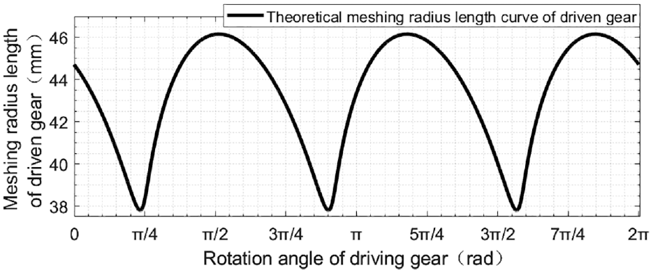
Instantaneous meshing pole radius curve of the driven gear.
At last, takes
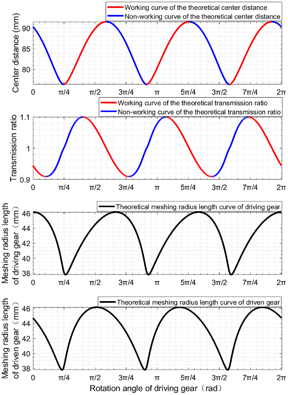
The working conditions model of the variable center distance non-circular gear pair.
Classification and analysis of instantaneous meshing arcs
Grouping of instantaneous meshing arcs
The definition of the associated instantaneous meshing arc and the associated instant are given as follows.
Assume that
And the associated instant of
Based on the definition above, the associated instantaneous meshing arcs of the instantaneous meshing arc pair
In order to further elucidate the relationship of any instant and the instantaneous meshing arcs meshing at that instant, to the associated instant and the associated instantaneous meshing arcs, another method used to find the associated instant and the associated instantaneous meshing arcs, apart from the definition above, is shown in the example below.
As shown in Figure 12,

An example of the associated instantaneous meshing arc (a) and the associated instant (b).
Finally, as shown in Figure 12(b), the associated instantaneous meshing arcs of
Classification and analysis of instantaneous meshing arc group
According to Section “Introduction,”
Assuming that
Thirteen categories of

Afterwards, according to the categories of
(1) Among them, the
(2) As shown in rows 2 and 5 of Table 1, the
(3) As shown in rows 3 and 6 of Table 1, the
(4) All the instantaneous meshing arc groups which do not belong to
There is
There are
There are two identical working conditions
Here is the classification and analysis of the variable center distance noncircular gear pair’s instantaneous meshing arc group. Then, the rounding algorithms suitable for the instantaneous meshing arcs in
The meshing model and the rounding algorithm of the instantaneous meshing arc pair
In this section, the general meshing model of the instantaneous meshing arc pair on the variable center distance non-circular gear pair will be established and analysis, and the constant center distance rounding algorithm and the constant transmission ratio rounding algorithm suitable for the instantaneous meshing arcs in
General meshing model of the instantaneous meshing arc pair
Assume that the rotation angle

Before the rounding process of

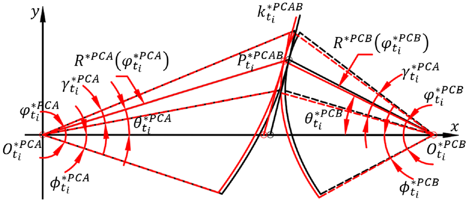
General meshing model of the instantaneous meshing arc pair before rounding.
During the meshing simulation process of

Based on the meshing theory,
1
the arc length


By keeping


When instant


It can be seen from Figure 13 and formula (8) that the angle

Based on formulas from (6) to (10), the general meshing model of


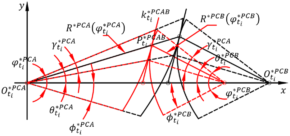
General meshing model of the instantaneous meshing arc pair after rounding.
And based on Figure 14 and formula (9),

Suppose that,


And based on the meshing theory, it can be known that:

Finally,


Constant center distance rounding algorithm
Based on the meshing theory,
1
after rounding,


In order to make sure the instantaneous center distance unchanged before and after rounding, thus,

Then,

The slope

Also,

With the help of formulas from (20) to (26),
Instantaneous meshing arcs before and after the constant center distance rounding algorithm.
By substituting

And that is the constant center distance rounding algorithm suitable for the instantaneous meshing arc group category 1 and 2.
Constant transmission ratio rounding algorithm
In order to make sure the instantaneous transmission ratio before and after rounding are equal, the following two assumptions can be made:
In formula (13), the value of
Based on the above assumptions, according to the formulas from (1), (6), (7), (8), (9), (10), (13), and (14), it is easy to obtained that
Then the meshing state of
Instantaneous meshing arcs before and after the constant transmission ratio rounding algorithm.
There must be a proportionality coefficient


Then according to the formulas (15) and (16), it can be known that:
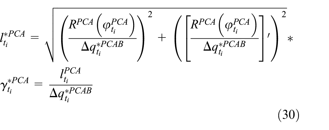

Combining this equation with formulas (30) and (31), it can be seen that
Put the formulas (28) and (29) into the formula (19), the result can be obtained as shown in formula (32):

Which can prove that the instantaneous transmission ratio remains unchanged during this constant transmission ratio rounding process, therefore, the above-mentioned constant transmission ratio rounding algorithm can round the instantaneous meshing arc group category 1 and 3 without change the instantaneous transmission ratio of it.
While

And that is the constant transmission ratio rounding algorithm suitable for the instantaneous meshing arc group category 1 and 3.
Dynamic allocation strategy of rounding amount
In order to get reasonable pitch curves which can be divided evenly by standard pitch after rounding, this section proposes a dynamic allocation strategy to distribute rounding amount on each instantaneous meshing arc pairs. And the flowchart of this strategy is shown in Figure 17.

Flow chart of the dynamic allocation strategy of rounding amount.
The rounding amount allocating process under this strategy usually contents several rounds which depends on the rounding amount pool is empty or not. At the beginning of all rounds, the raflag of the meshing instantaneous arc pair in ArcSet_1, ArcSet_2, and ArcSet_3 will be set to 0, and the raflag of the meshing instantaneous arc pair in ArcSet_4 will be set to 1, total rounding amount will fill into the pool.
Then, in each round, the rounding amount allocating process starts from the initial rounding instantaneous meshing arc group which is the instantaneous meshing arc group in
Assume that
So, the rounding amount


And the rounding amount distributed on the instantaneous meshing arcs which belongs to category 4 is zero, because their round amount flag are 1.
Then use the rounding algorithms mentioned above to round the instantaneous meshing arc pair belong to
When the instantaneous meshing arc pair belongs to
When the instantaneous meshing arc pair belongs to
After that, use the curvature radius of the instantaneous meshing arcs as a necessary condition to verify whether the pitch curves are reasonable after rounding, the curvature radius
The sign of
When
When
And the curvature radius
Assume that

According to formula (1), the rotation angle from


Assume that,
Then, the common tangent circle of


And the curvature radius

In the same way, the curvature radius
After all instantaneous meshing arc pairs’ rounding amount allocating process is complete in round
Applicable scope
As mentioned in this section, whether a pair of parallel-axis variable center distance non-circular gear can be rounded by the method described in this research is usually depends on the instantaneous meshing arcs in the instantaneous meshing arc group category 1, 2, and 3 of the gear pair is enough for the total rounding amount to be completely and reasonably distributed on. So, in the research field of parallel-axis non-circular gear pair, this round method can mainly be used to round three types of the parallel-axis non-circular gear pair:
(1) Fixed center distance non-circular gear pair
In the research field of non-circular gear pair, most research and applications are focus on non-circular gear pair with fixed center distance, such as picking and planting mechanism,31,32 silk reeling machine, 33 robot,34–36 engine, 37 and etc. As a special case of the variable center distance non-circular gear pair, fixed center distance non-circular gear pair can surely be rounded by the method described in this research.
When its center distance can be fine-tuned in the design process, then the center distance curve of such gear pair can be seen as a non-working curve, and all instantaneous meshing arcs on the driving and driven gear’s pitch curves can be grouped and classified into
When the gear pair’s center distance is already given at the beginning of the design, then the center distance curve of such gear pair can be seen as a working curve, and all instantaneous meshing arcs on the driving and driven gear’s pitch curves can be grouped and classified into
(2) Variable center distance non-circular gear pair
For variable center distance non-circular gear pair composed of two non-circular gears,
30
the instantaneous meshing arcs on the driving and driven gear’s pitch curves can be grouped and classified into
(3) Variable center distance circular and non-circular gear pair
As a special case of the variable center distance non-circular gear pair, the conditions for the circular and non-circular gear pair composed of a circular gear and a non-circular gear38–40 to be rounded by the method described in this research is different from the variable center distance non-circular gear pair mentioned in (2).
Since part of the circular and non-circular gear pair is a circular gear, during the rounding process, the rounding amount will be evenly distributed on the pitch curves of the circular gear as well as the non-circular gear, which means, every instantaneous meshing arc’s round amount on the gear pair’s pitch curves is directly proportional to its arc length, even if the round amount of the instantaneous meshing arc belongs to the instantaneous meshing arc group category 4 is not zero. However, the instantaneous meshing arcs belong to
Example and analysis of the pitch curves’ rounding process of the variable center distance non-circular gear pair based on working conditions
In this section, a variable center distance non-circular gear pairs’ theoretical pitch curves will be taken as an example to be rounded and analyzed to prove the correctness and effectiveness of the theory and method mentioned above.
The polar coordinate function

And

Theoretical pitch curve of driving gear.
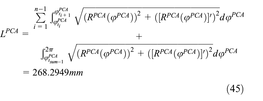
The pitch curve length
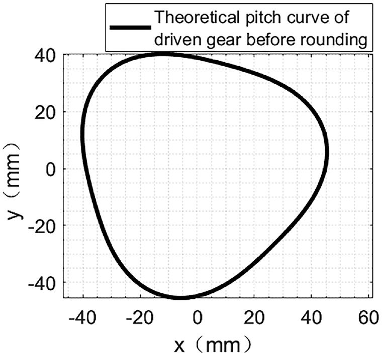
The polar coordinate function
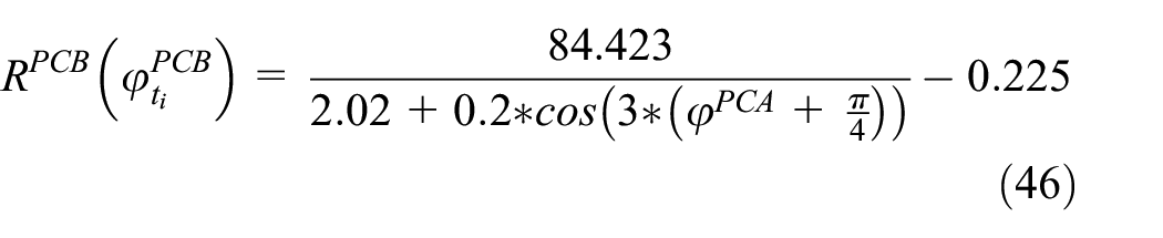
And

Theoretical pitch curve of driven gear.
The pitch curve length

When the gear pair’s modulus
Assuming that the teeth number of the driving gear and the driven gear after rounding is 42, and the theoretical center distance curve

The theoretical center distance curve of the variable center distance non-circular gear pair based on working conditions.

The theoretical transmission ratio curve of the variable center distance non-circular gear pair based on working conditions.
Based on the theory and methods in Section “The working conditions model of the variable center distance non-circular gear pair,” the meshing condition of the variable center distance non-circular gear pairs can be established as shown in Figure 22.

The working conditions model of the variable center distance non-circular gear pair.
By dividing the meshing time of the gear pair into 3600 meshing instants, based on the method in Section “Classification and analysis of instantaneous meshing arc group,” all the instantaneous meshing arcs meshing at same associated instant can be grouped and classified into four categories. Then, the meshing radius curves formed by the instantaneous meshing arcs in the instant meshing arc groups which belongs to

Instantaneous meshing arc groups in

Instantaneous meshing arc groups in

Instantaneous meshing arc groups in

Instantaneous meshing arc groups in
After calculation, it can be seen that the ratio of the total arc length of the gear pair’s instantaneous meshing arc group category 1, 2, and 3 to the gear pair’s pitch curves length is 71.42%. Therefore, it can be preliminarily judged that this variable center distance non-circular gear pair can be rounded by the method described in this research.
According to Section “Dynamic allocation strategy of rounding amount,” after the rounding amount allocating process, the rounding amount distribution on each pair of instantaneous meshing arc can be obtained, and so as the rounded pitch curves of the variable center distance non-circular gear pair as shown in the Figures 27 and 28. The theoretical pitch curves of the variable center distance non-circular gear pair also shown in these figures for comparison purpose.
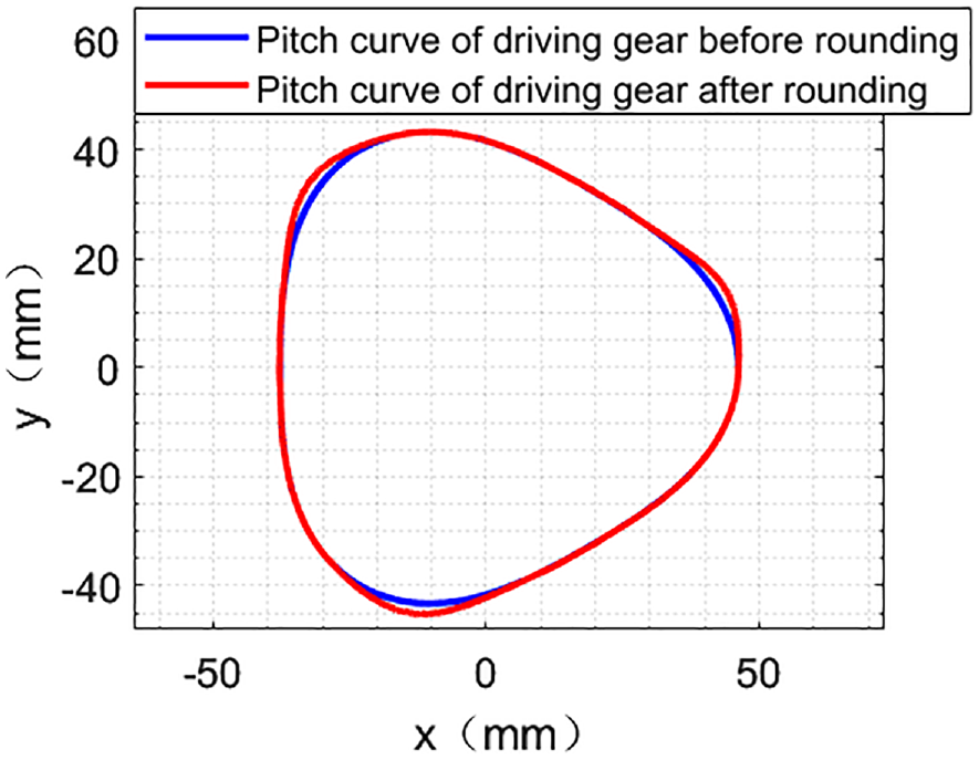
The rounded pitch curves of the driving gear.
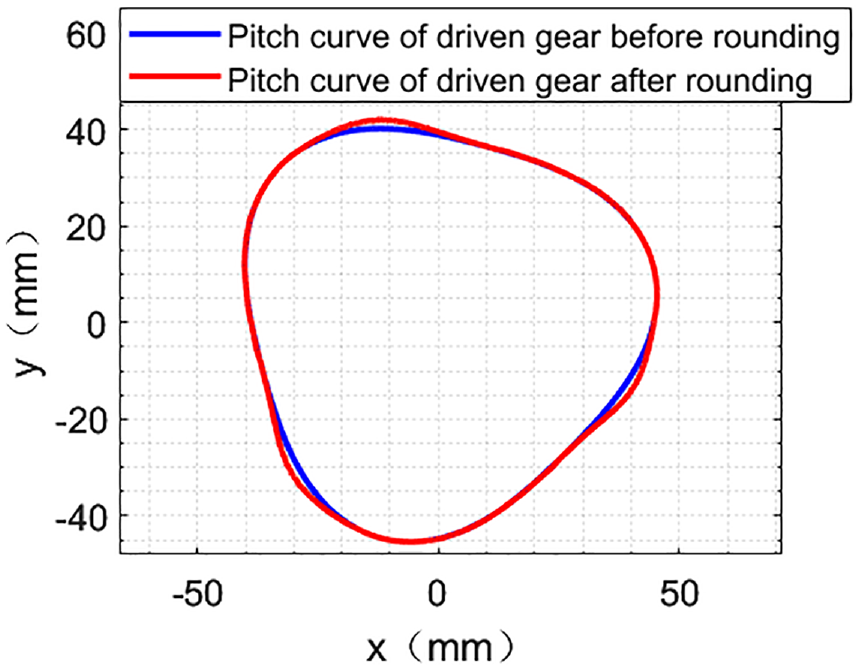
The rounded pitch curves of the driven gear.
And the radial difference curve of the pitch curves of the variable center distance non-circular gear pair before and after rounding are shown in Figures 29 and 30.

The radial difference curve of the driving gear’s pitch curve before and after rounding.

The radial difference curve of the driven gear’s pitch curve before and after rounding.
It can be seen from the radial difference curves that, the max radial difference of the driving gear before and after rounding is 2.09 mm, and the max radial difference of the driven gear before and after rounding is 1.93 mm.
Based on the rounded pitch curves in Figures 27 and 28, the center distance and transmission ratio curves after rounding can be obtained and shown in Figures 31 and 32 after the meshing simulation. For comparison purpose, the theoretical center distance curve and the theoretical transmission ratio curve of the variable center distance non-circular gear pair also shown in these figures.

The center distance curve of the variable center distance non-circular gear pair after rounding.

The transmission ratio curve of the variable center distance non-circular gear pair after rounding.
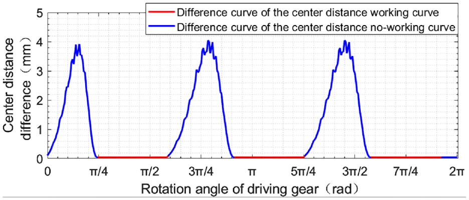
And the difference curves of the center distance curve and the transmission ratio curve of the variable center distance non-circular gear pair before and after rounding are shown in Figures 33 and 34.

The difference curve of the center distance curve before and after rounding.
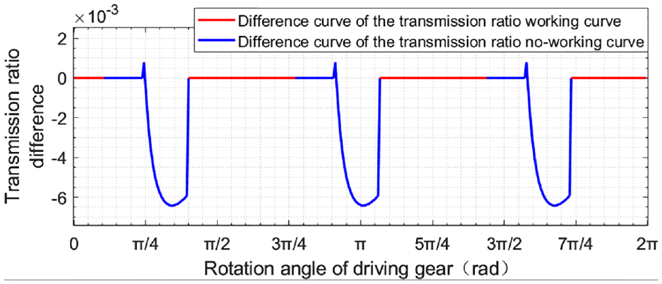
The difference curve of the transmission ratio curve before and after rounding.
It can be seen from Figures 33 and 34 that, the working curve of the center distance and the transmission ratio remain unchanged after the rounding process, and the max difference of the center distance no-working curve after rounding is 3.88 mm, and the max difference of the transmission ratio no working curve after rounding is 0.00648.
Based on the rounded pitch curves of the gear pair, with the help of the CNC gear shaping machine (type YKS5132X3/297 equipped with SIEMENS SINUMERIK 802Dsl system) and the G-code used to control the CNC, the driving gear and the driven gear of the rounded variable center distance gear pair can be obtained and shown in Figures 35 and 36 after the shaping process

Rounded driving gear.
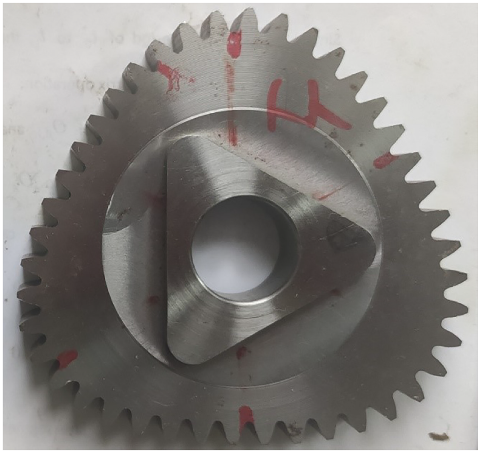
Rounded driven gear.
As shown in Figure 37, by testing the variable center distance non-circular gear pair on the double-flank gear tester mentioned in previous research, 41 the gear pair’s meshing characteristics can be obtained.

Variable center distance non-circular gear pair.
After the testing, the real center distance curve and the real transmission ratio curve of the rounded gear pair can be got as shown in Figures 38 and 39. For comparison purpose, the theoretical center distance curve and the theoretical transmission ratio curve of the variable center distance non-circular gear pair also shown in these two figures.

The real center distance curve of the rounded variable center distance non-circular gear pair.
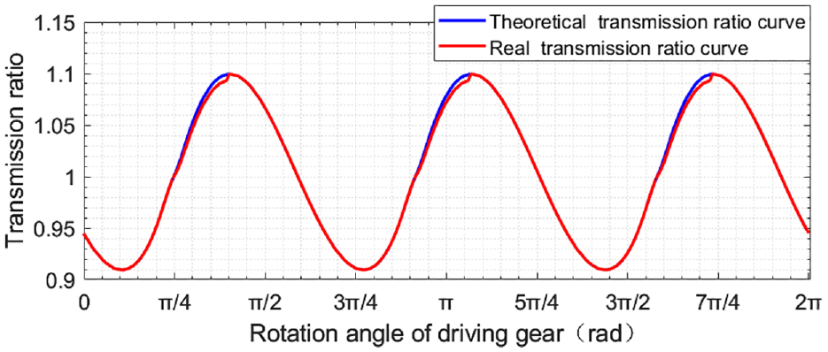
The real transmission ratio curve of the rounded variable center distance non-circular gear pair.
The center distance difference curve from the actual center distance to the theoretical center distance is shown in Figure 40.
The transmission ratio difference curve from the actual transmission ratio to the theoretical transmission ratio of the gear pair.
And the transmission ratio difference curve from the actual transmission ratio to the theoretical transmission ratio is shown in Figure 41.

The transmission ratio difference curve from the actual transmission ratio to the theoretical transmission ratio of the gear pair.
It can be seen from the above Figures 38 to 41 that the working curves on the real center distance curve and the real transmission ratio curve of the variable center distance non-circular gear pair after round are almost consistent with the working curves on the theoretical center distance curve and the theoretical transmission ratio curve of the gear pair. And the max difference of the center distance working curve from the actual center distance to the theoretical center distance is 45.5 μm, the max difference of the transmission ratio working curve from the actual transmission ratio to the theoretical transmission ratio is 0.000136. By analogy to the accuracy standard of circular gears, it can be seen that the difference of the center distance working curve and the transmission ratio working curve are basically meet the accuracy requirements, thus proving the correctness and effectiveness of the above rounding theory and method.
Conclusions and outlook
Based on the working conditions of the variable center distance non-circular gear pair, this research provides the rounding theories and methods for the theoretical pitch curves of the gear pair to ensure the designed theoretical pitch curves can be evenly divided by the pitch without change its modulus, which can decrease the design and manufacturing costs of the variable center distance non-circular gear pair. Theoretically, there are four main contributions in this work:
Proposed a novel approach, which not only can divide the theoretical center distance curve and transmission ratio curve into working curves and non-working curves based on the working conditions, but also can build the working condition model of the gear pair to reveal the relationship between the working curves, the non-working curves, and the gear pair’s theoretical pitch curves.
A comprehensive method is proposed for group and classify all the instantaneous meshing arcs into four categories based on the geometric shape, the rounding algorithm adaptability, and the categories of instantaneous working conditions corresponding to them.
Developed a constant center distance rounding algorithm and a constant transmission ratio rounding algorithm, which can be used to round the instantaneous meshing arcs in arc group category 1, 2, and 3.
Proposed a dynamic allocation strategy for distribute the total rounding amount on the pitch curves, to reasonably distribute the rounding amount on the pitch curve.
Carried out a variable center distance non-circular gear pairs’ theoretical pitch curves as an example to be rounded and analyzed, the results successfully proved the correctness and effectiveness of the above rounding theory and method.
Although the above rounding theory and method achieve the goal of rounding the theoretical pitch curves of the variable center distance non-circular gear pair without change its modulus, there are still many works to do to improve and extend them:
Although cannot be rounded by the rounding theory and method mentioned in this research, the instantaneous meshing arc groups may be rounded by a complicated rounding process may still exist in ArcSet_4. So, in order to separate and round the arc groups that can be rounded from the arc groups cannot be rounded at all, method used to subdivide and round the instantaneous meshing arc groups in ArcSet_4 may be proposed in the further studies.
In each round of the rounding process, the rounding amount distributed on the instantaneous meshing arcs with RAflag = 0 at the first time is equal. When the rounding amount is relatively large, this rounding amount distribute strategy may cause the rounding strategy to spend more rounds as well as more time to round the current pitch curves. So, to improving the efficiency of the rounding amount dynamic allocation strategy in this research, a suitable rounding amount distribution function used to distribute the round amount more reasonable at the beginning of each round may be proposed.
The rounding theory and method mentioned in this research is applied in the parallel shaft transmission field, however, the above theories and methods can also be learned and improved in the field of non-parallel shaft transmission to solve their rounding problems.
Footnotes
Appendix
Handling Editor: Chenhui Liang
Declaration of conflicting interests
The author(s) declared no potential conflicts of interest with respect to the research, authorship, and/or publication of this article.
Funding
The author(s) received no financial support for the research, authorship, and/or publication of this article.