
Abstract
The origami mechanisms possess numerous unique advantages, including folding, reconfigurability, and multi-stability. The presence of multi-stability introduces a novel concept for the design of constant force mechanisms (CFM). In this study, we present a CFM with multi-segment constant-force regions by leveraging the multi-stable characteristics of the origami mechanism. The design principle behind this CFM involves combining an accordion origami structure with positive stiffness and a Kresling origami structure with multi-segment negative stiffness regions. To achieve zero stiffness, the Kresling origami structure is aligned parallel to the accordion origami. To effectively utilize both the Kresling and accordion origamis, we have established a mechanical model that describes their respective stiffness characteristics to establish design rules for the constant-force mechanism. By carefully designing the parameters of these two origami structures, we evaluate how variations in the structural parameters of Kresling influence the constant force properties of our proposed multi-segment CFM. To illustrate its inherent property of providing constant force across multiple segments, we employ finite element analysis and experiments to obtain force-displacement curves for our mechanism. The results demonstrate the feasibility of our presented design method which paves the way for constructing a simple CFM.
Introduction
Precision manipulation has been employed in robotics, automatic assembly, medical equipment, and precision manufacturing. 1 Contact force control is an important issue in the process of precision operations. Flexible parts are more sensitive to variations in contact force. For example, during surgery, it is necessary to control the contact force to avoid harm to the human body. In micro-assembly processes, the contact force between the manipulator and objects can be adjusted to prevent damage to the objects. The constant force performance of flexible mechanisms has been applied in these precision manipulations that require force control. 2 Unlike traditional variable-force mechanisms, a constant-force mechanism can maintain a consistent contact force when the manipulator interacts with objects. Additionally, a constant-force mechanism provides a means of regulating the contact force.
Conventionally, the constant force is achieved using the control method. A force sensor is installed to monitor the contact force between the operating system and objects to construct a force feedback control system. 3 For example, to prevent binding in the automatic assembly, a force control system is required to maintain a constant force state. The advantage of this force control method is that it can provide a reliable and precise constant force situation. However, this method needs complicated control equipment and a complex control strategy to achieve the adjustment of the constant-force magnitude.
Due to the complexity of the above control method, a kind of mechanism named constant-force mechanisms (CFMs) has been developed. 4 CFMs can provide a near-constant force over a certain displacement range. From the mechanical view, the stiffness of CFMs is near zero over a prescribed motion range. There are five kinds of traditional rigid constant-force mechanisms such as curved surface CFM, double-slider CFM, hinged-lever CFM, oblique springs CFM, and C-shape CFM. Curved surface CFM can provide the constant force by designing a slider with a curved surface so that the squeezing between sliders generates the decomposed constant force. Double-slider CFM is composed of two pairs of spring-sliders in orthogonal. A ram between the two sliders converts the input force into a constant force. Hinger-lever CFM generates a constant force utilizing a lever and a pre-tensioned spring that has a force-displacement relationship from the origin. C-shaped spring CFM utilizes a spiral wound on a tight drum that generates a constant force when a tensile force acts on it.
To overcome the drawback of traditional rigid constant-force mechanisms, compliant mechanisms are developed to design CFMs that provide advantages such as no friction, no backlash, and low cost.5–7 Four types of compliant CFMs, such as stiffness-combination CFM, curved-beam CFM, shape-optimized CFM, and cross-spring CFM, were proposed to explore the design principle of compliant CFMs. Stiffness-combination CFM achieves constant force by using a combination of positive-stiffness and negative-stiffness mechanisms in parallel. The design principle of curved-beam CFM is also employing zero-stiffness that is generated by special-shape beams. 8 The principle of the shape-optimization CFM is the same as curved-beam CFM. They all output a constant force by optimizing the shape and structural parameters of the compliant mechanism. The cross-spring CFM consists of two identical leaf flexures that have positive stiffness performance. Therefore, the above compliant constant-force mechanisms can generate zero stiffness by carefully designing the flexure components.
The zero stiffness can be obtained by paralleling a positive-stiffness mechanism to a negative-stiffness one. 9 The force-displacement relationship of the positive-stiffness mechanism follows Hook’s law. The negative-stiffness mechanism represents that the reactive force is inversely proportional to its displacement. The negative-stiffness performance usually occurs when the mechanism is a bistable structure with buckling characteristics. Origami structures have revealed that varying geometric parameters can lead to tailorable stiffness and multi-stability properties. It is worth exploring how to make use of the multi-stability of origami to design constant-force mechanisms.
Furthermore, the existing CFM only has one constant-force magnitude.6–8 The multi-segment negative stiffness property of origami structures provides the possibility of CFM with multi-segment constant-force ranges. Kresling origami is the arrangement of alternating mountain and valley creases around the circumference.10–12 This origami mechanism exhibits multi-stability.13–15 In this paper, we introduce a design method for CFM using a Kresling origami structure.
The origami mechanism comprises a series of interconnected creases that are folded into various shapes and patterns, resulting in its motion.12,16–18 The parallel mechanism consists of multiple sub-chains arranged in parallel to achieve multiple degrees of movement through rigid bars and kinematic pairs.19,20 While both mechanisms share similarities in terms of their structure and design, they also exhibit several differences. The kinematics of the origami mechanism are equivalent to an interconnecting bar structure, requiring consideration for bar deformation.21,22 Both mechanisms employ connected components to achieve desired movement and functionality; however, the origami mechanism is based on folding principles whereas the parallel robot mechanism relies on principles related to movement among rigid kinematic pairs. In conclusion, the origami mechanism and the parallel robot mechanism represent two distinct types of mechanical systems with their own unique characteristics. Compared to parallel mechanism, origami mechanisms offer numerous advantages including foldability, reconfigurability, and multi-stability. The presence of multi-stability in origami mechanisms provides an innovative concept for designing constant force mechanisms (CFM).
This paper aims to explore the design of a multi-range constant-force origami mechanism. In Section “Design of origami mechanism with single segment constant force range,” a design method of a one-segment constant-force origami mechanism using one-layer Kresling origami is presented. On this basis, we use multi-layer Kresling origami to achieve a multi-segment constant-force mechanism in Section “Origami mechanism with multiple segment constant force regions.” The conclusion and discussion are outlined in Section “Conclusions.”
Design of origami mechanism with single segment constant force range
Design concept
The constant-force mechanism is a kind of mechanism whose output force remains constant when the input displacement increases. From the stiffness point of view, the stiffness of the mechanism is zero. Zero stiffness can be generated by using the offset of positive and negative stiffness. The design concept of zero-stiffness origami is illustrated in Figure 1. When the two origami structures are in parallel, the stiffness is the sum of the two origami structures. To obtain the zero stiffness, we apply one origami with positive stiffness and another origami with negative stiffness. There are two problems to be solved. One is to design the origami mechanism with positive and negative stiffness; second, the stiffness value of the two origami structures is the same. Kresling origami exhibits bi-stability that causes the negative stiffness region of the structure. Next, we built the mechanical model of Kresling origami to depict its stiffness performance.

Design concept of constant-force origami mechanism.
Stiffness analysis of the Kresling origami
The Kresling origami mechanism, as mentioned in Cai et al., 10 will demonstrate a buckling phenomenon and give rise to a region of negative stiffness during the process of instability. A flat sheet which is the arrangement of mountain and valley creases around the circumference is folded into a three-dimensional Kresling origami structure as shown in Figure 2. The origami consists of n triangular elements whose sides are a, b, and c. The height of the origami is h.

Structural parameters of one-layer Kresling origami structure.
A truss structure is adopted to depict the stiffness behavior of the Kresling origami.13–15 The creases are treated as bars or trusses that deform axially, resulting in stretching and shearing of the triangular facets. The origami structure is equivalent to a truss, that is to say, all the creases are replaced by two-force bars, without considering the deformation of the triangular panels.
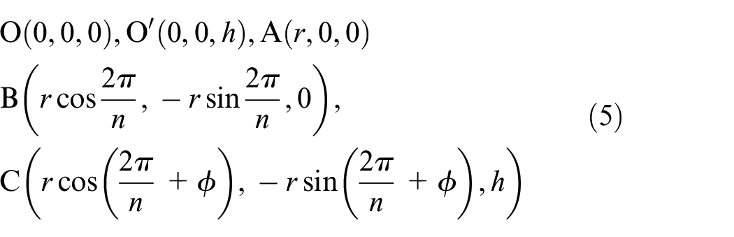
The unit cell of a triangulated cylinder pattern from the crease pattern. At the planar state,

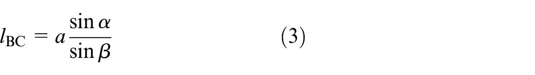
And the law of sines gives

Thus,

The height
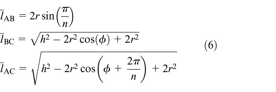
Then the length of the horizontal crease AB, mountain crease BC, and valley crease AC at the folded state are given by
We employ a truss structure to establish the mechanical model of the Kresling origami mechanism, which is exclusively capable of undergoing tensile deformation. In accordance with the definition of strain in material mechanics for tension members, this strain is defined as the ratio between the change in length and the initial length of the bars. The strains in these three creases are


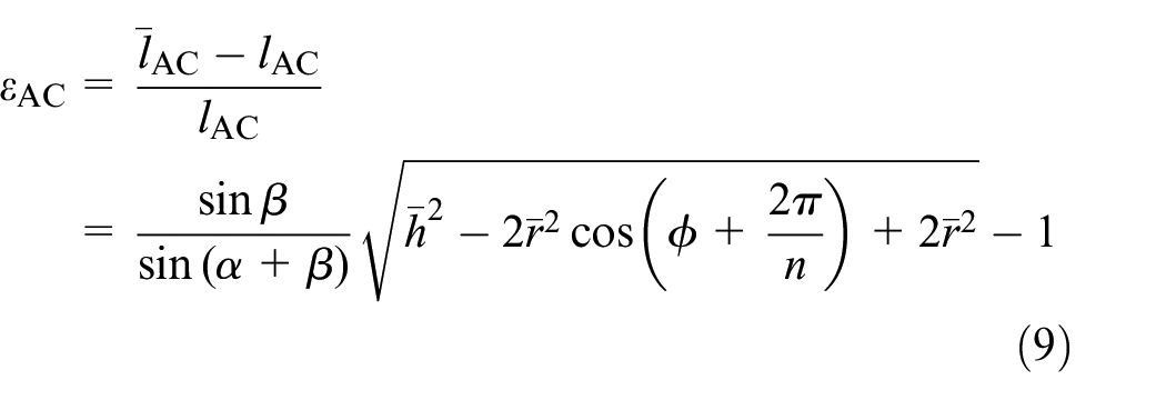
where
The potential energy of the origami structure is

where

where

Combining equations (10) and (12), we can draw the force-displacement curve that describes the stiffness performance of the Kresling origami. Next, we analyze the effect of the parameters height
To analyze the effect of the parameter

Stiffness properties with different twist angles: (a) force-displacement relationship that captures the negative stiffness, (b) negative stiffness values correspond to different twist angles, (c) negative stiffness region, and (d) critical forces correspond to the region where negative stiffness occurs.
The first one is that the negative stiffness values are different. To analyze the change of the negative values, we fit the force-displacement curve in the negative stiffness region as shown in Figure 3(b). The negative stiffness value can be obtained by calculating the slope of the fitted line. The negative stiffness is smaller with the increase in the twist angle
The second difference is the length (
The third difference is the critical force
To illustrate the effect of the height of Kresling (

Stiffness properties with different heights: (a) force-displacement relationship that captures the negative stiffness, (b) negative stiffness values correspond to different heights, (c) negative stiffness region, and (d) critical forces correspond to the region where negative stiffness occurs.
We analyze the influence of the number of elements on the negative stiffness as the number (n) is set to 5–8. The influence is shown in Figure 5(a) to (d). We can come to the following conclusion: The number has no significant effect on the negative stiffness value and the critical force and has little effect on the length of the negative stiffness region. We determine the structural parameters without considering the effect of the number.

Stiffness properties with a different number of elements: (a) force-displacement relationship that captures the negative stiffness, (b) negative stiffness values correspond to different numbers of elements, (c) negative stiffness region, and (d) critical forces correspond to the region where negative stiffness occurs.
Positive-stiffness origami mechanism
The origami structure with positive stiffness is illustrated in Figure 6(a). The structure consists of two symmetrical triangular origami that are composed of three identical folding units. The folding unit is constructed through two rectangular panels at a dihedral angle

Structure and model of the origami mechanism with positive stiffness: (a) origami structure with positive stiffness, (b) equivalent truss model of the accordion origami, and (c) geometry relation of one element of origami before and after folding.
To build the mechanical model of the origami, the truss structure (Figure 6(b)) is applied to capture the positive stiffness characteristics of the origami. In the unfolded state, the geometry relationship is given by

In the folding state, the length of the bar DE can be obtained using the geometry relation shown in Figure 6(c).
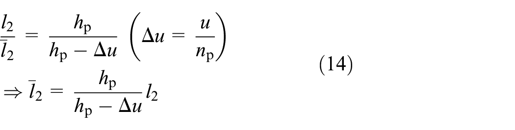
The strain of the bar after folding is given by

As can be seen from the Figure 6(b), the origami structure is composed of

where
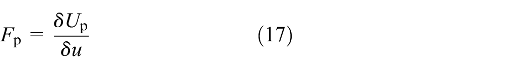
Using the relationship between work and energy, the force can be given
According to the definition of stiffness, the stiffness of the origami structure can be obtained by using equation (16).
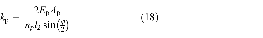
Equation (18) shows that the stiffness of the origami mechanism can be adjusted by varying the parameters
To validate the feasibility of the proposed origami, we carried out the numerical and analytical analysis of the stiffness of the origami mechanism. The elastic module and Poisson’s ratio are 2 GPa and 0.3, respectively. The finite element mesh is divided into S4R shell elements, the mesh size is 2 mm. The force-displacement relation of the mechanism is shown in Figure 7(b). The numerical results using the finite element method agree with the theoretical values. The force-displacement curve is a positive linear relationship. The result indicates that the origami mechanism exhibits positive stiffness.

Origami structure with positive stiffness: (a) FEM model and (b) force-displacement curve of the origami mechanism.
Design process and stiffness analysis of CFM
The Kresling and accordion origami mechanism exhibits negative and positive stiffness properties. The Kresling origami structure is parallel to the accordion origami to match zero stiffness. The constant-force origami mechanism consists of Kresling and accordion origami. The constant-force origami mechanism is shown in Figure 8. In Figure 8, we have included four photographs depicting the states of positive, negative, and zero stiffness in the single-layer Kresling origami mechanism. The occurrence of negative stiffness can be attributed to the mechanical behavior exhibited during the instantaneous snap-through (buckling) process of the origami mechanism. By connecting an Kresling origami mechanism with negative stiffness in parallel with one (accordion origami) possessing positive stiffness, a mechanism exhibiting zero stiffness can be achieved.

Structure of the origami mechanism with constant force.
Based on the stiffness model of the Kresling and accordion origami structures, the matching method to form zero stiffness is as follows: (i) The negative stiffness valve (−Kn) is calculated according to the model of the Kresling origami structure. (ii) The positive stiffness value (Kp = Kn) can be obtained according to the matching rule. (iii) Reasonably determine the parameters of the accordion origami mechanism to obtain zero stiffness. Using the matching method, we can determine the structural parameters of the Kresling and accordion origami. The structural parameters of Kresling are as follows:
To validate the effectiveness of the design concept, we draw the force-displacement curves that describe the stiffness of Kresling, and accordion origami. The stiffness of the accordion origami is 0.86 N/mm, and the stiffness of the negative stiffness region of the Kresling origami is −0.92 N/mm. Since the positive and negative stiffness is close, it indicates that the approximate zero stiffness can be achieved through positive and negative stiffness matching. The force-displacement curve that captures the constant-force characteristics of the proposed mechanism is demonstrated in Figure 9(a). The curve has a region that approximates constant force. The result shows the presented design method is feasible.

Verification analysis of constant force mechanism: (a) force-displacement curves of mechanisms with positive, negative, and zero stiffness, respectively and (b) comparative analysis of the analytical and FEM.
To further illustrate the correctness of the design method for the constant-force mechanism, we apply the finite element software Abaqus to analyze the stiffness performance. The theoretical and finite element results are shown in Figure 9(b). The theoretical curve is close to the FEM. We compare the constant-force values and the range of constant force. The theoretical value and range are 20.2 N and 9.7 mm, and the finite element results are 21.6 N and 10.5 mm. The difference between these values is 1.4 N and 0.8 mm. These results show the proposed mechanism exhibits constant force characteristics. However, the analytical model ignores the crease torsion and the deformation of the panels of the origami. This simplification is the reason for the differences between the analytical model and the finite element model.
The magnitude and range of constant force are used to evaluate the constant force characteristics of the origami mechanism. These two constant force performance indices depend on the critical force

The influence of structure parameters on the constant force: (a) effect of twist angle
Origami mechanism with multiple segment constant force regions
In Section “Design of origami mechanism with single segment constant force range,” the one-segment constant force mechanism is composed of a single-layer Kresling origami structure and accordion origami with linear positive stiffness.17–19 There is only one constant force range. In the practical engineering field, the multi-segment constant force mechanism (MSCFM) is needed to operate different objects. For example, when microgrippers are demanded to manipulate objects with different hardness, we need a multi-segment constant force mechanism to design the microgrippers that can prevent damage to the manipulating objects due to excessive forces between the gripper and the objects. The design idea of a single-section constant force mechanism can be extended to design multi-segment constant mechanisms. The design concept of MSCFM is illustrated in Figure 10(a). The idea is to use the multi-stability of origami to obtain the multi-segment negative stiffness regions. The origami with multi-stability is parallel to the origami with linear stiffness resulting in multi-segment constant force ranges.
The single-layer Kresling origami is a bi-stable mechanism, and multiple one-layer Kresling structures are connected in series to construct a multi-stable origami mechanism. Figure 10(b) shows the structural design of a three-segment constant force mechanism. The origami mechanism is composed of a three-layer Kresling and an accordion origami. The accordion origami is embedded in Kresling origami in parallel.
Figure 11(a) shows the design idea for the multi-segment constant force origami mechanism. Multi-layer Kresling origami with multi-segment negative stiffness is parallel to accordion origami with positive stiffness. To construct multi-section zero stiffness ranges, each layer Kresling unit exhibits the same negative stiffness to match accordion origami due to its single positive stiffness. As a result, the structural parameters of each unit are the same. Furthermore, the multi-layer Kresling occurs buckling layer by layer from top to bottom with the increase of force, so that it exhibits the differences in the locations of the regions with negative stiffness. That is the reason why multi-segment regions with different zero-stiffness ranges can be formed. The parameters of the Kresling unit can be obtained by matching zero stiffness as follows: (i) First, we determined initially the parameters of the Kresling that enables it to exhibit negative stiffness. The parameters of Kresling shown in Figure 2 are as follows:

Design of multi-segment constant force origami mechanism: (a) design concept and (b) structure of multi-segment constant force origami mechanism.
To showcase the multi-segment negative stiffness region of our proposed origami structure, we conducted an experiment that is presented in Figure 12. As depicted in Figure 12, during a gradual increase in load, it was observed that the three-layer origami structure exhibited instability from the upper layer to the lower layer rather than simultaneous buckling of all layers. In other words, this resulted in three instances of instability within the origami structure leading to three stages of negative stiffness. The force-displacement relationship also confirms multiple regions with negative stiffness.

Demonstration of multi-segment negative stiffness of multi-layer origami structure using experimental test.
To illustrate the effectiveness of the design concept, we first demonstrate the multi-segment negative stiffness properties of the multi-layer Kresling origami mechanism. The truss is used to capture the stiffness of the mechanism (Figure 13(a)). The material utilized in the origami mechanism is polypropylene, with an elastic modulus of 2 GPa. In the equivalent model, only the elastic deformation of the creases is taken into consideration. Considering the thickness of the origami structure, a cylindrical bar with a radius of 0.1 mm is employed to represent the mechanical properties of the crease. The cross-sectional area of equivalent bars can be calculated as

Stiffness performance of multi-unit Kresling origami: (a) truss and FEM model capturing the stiffness performance of Kresling origami, (b) force-displacement curve for the Kresling origami, and (c) negative stiffness values correspond to each region.
To master the magnitude of each segment’s negative-stiffness region, the curve segment of the negative stiffness region is fitted (shown in Figure 13(c)). The slopes of each fitting line are the negative stiffness values. These values are −0.28 N/mm (region I), −0.25 N/mm (region II), and −0.29 N/mm (region III), respectively. The stiffness values differ so little that they are almost identical. The above analysis shows that the triggering conditions (critical force) of the three negative stiffness regions are different, but the negative stiffness values are the same. This property of multi-layer Kresling origami follows the design concept shown in Figure 11(a).
To demonstrate the multi-segment constant force property, we employed FEM to obtain the force-displacement curve (Figure 14(b)) of the mechanism depicted in Figure 11(b). The red dashed line indicates regions with constant force, each having a distinct magnitude. Within each region, the constant force increases due to progressively increasing critical forces that activate individual segments within the negative stiffness region. The externally applied force can be adjusted to control the desired value of constant force. The reason for incorporating a negative stiffness region prior to each constant-force region is as follows: In Kresling origami, stiffness varies with displacement within its negative stiffness range. If the absolute value of negative stiffness exceeds positive stiffness before reaching zero-stiffness, their combination result in a preceding segment of negative stiffness followed by a zero-stiffness region. This phenomenon would not occur if an accordion origami structure with higher positive stiffness were used instead, as illustrated in Figure 15.

Force-displacement curve of multi-segment constant force origami mechanism: (a) experimental setup and (b) force-displacement curve using the finite element method and experiment test, respectively. The dashed line indicates the constant force regions. The black and red letters represent the constant forces and ranges of each segment by applying the finite element method and experimental test, respectively.

Influence of structural parameters on the constant force characteristics of multi-segment CFM: (a) force-displacement curves as the twist angles are 25°, 30°, and 35°, respectively and (b) force-displacement curves as the heights h are 50, 55, and 60 mm, respectively. The dashed line indicates the constant force regions.
The effectiveness of the proposed constant-force mechanisms was demonstrated through an experimental test utilizing a ball screw slide platform to uniformly apply a linearly increasing displacement to the mechanism. A force gauge mounted on the slide platform measured the interaction force between the platform and mechanism. Based on experimental data shown in Figure 14(b), the force-displacement curve illustrates that the origami mechanism exhibits three-segment constant force ranges consistent with FEM results. However, discrepancies between experiment and FEM can be attributed to manufacturing errors in the prototype due to its thin wall structure and limitations in accurately capturing forces and displacements using our measurement method. The occurrence of a negative stiffness region preceding each constant force region can be attributed to the following reason: The negative stiffness of Kresling origami varies with displacement. If the absolute value of negative stiffness surpasses that of positive stiffness prior to zero-stiffness occurrence, their superposition will still yield a negative stiffness segment, thus enabling its presence before reaching zero-stiffness region. This phenomenon does not occur when employing an accordion origami structure with higher positive stiffness, as depicted in Figure 15.
To evaluate the influence of the structural parameters of Kresling on the constant force properties of multi-segment CFM, we designed the CFMs as the twist angles
Conclusions
This paper presents a method for constructing a multi-segment constant-force mechanism using an origami mechanism. The design concept combines an accordion origami mechanism with positive stiffness and a Kresling origami mechanism with multi-level negative stiffness. To establish design rules for the constant-force origami mechanism, we developed an analytical mechanical model to describe the stiffness characteristics of the Kresling and accordion origami mechanisms using the truss model. We analyzed the force-displacement relationship, negative stiffness values, length of the negative stiffness region, and critical force required to match multi-segment zero-stiffness regions by adjusting the size parameters of the Kresling origami mechanism. This design concept and method enable construction of a CFM with a multi-segment zero-stiffness region using an origami mechanism. Simulated outcomes confirmed feasibility of this design concept; future work will focus on optimizing it for better constant-force performance. This design method can be extended to spatial CFMs; further research attention will be given to new applications including compliant grasp, micromanipulation, and vibration isolation.
Footnotes
Handling Editor: Chenhui Liang
Declaration of conflicting interests
The author(s) declared no potential conflicts of interest with respect to the research, authorship, and/or publication of this article.
Funding
The author(s) disclosed receipt of the following financial support for the research, authorship, and/or publication of this article: This work received funding from the National Natural Science Foundation of China (52165011, 51865016), Jiangxi Natural Science Foundation of Jiangxi Province – Key Project (20202ACBL204009), Jiangxi Natural Science Foundation of Jiangxi Province (20212BAB204028), Science and the Program of Qingjiang Excellent Young Talents, Jiangxi University of Science and Technology (JXUSTQJBJ2018006), Science and technology plan project of Ganzhou (2023PGX16964).