
Abstract
Quasi-Zero Stiffness (QZS) is essential for low-frequency passive vibration isolation, with the negative stiffness mechanism (NSM) being pivotal for achieving QZS. Mechanical spring-based NSMs often face issues like contact friction, parasitic high-frequency modes, and stiffness nonlinearity. This paper presents a new magnetic NSM designed to overcome these challenges effectively. The mechanism is applied to a Fast Steering Mirror (FSM) as a case study, enhancing its vibration isolation performance. Initially, a torque model for the magnetic NSM is established, exploring the impact of various structural dimensions on torque and nonlinear issues. The magnetic NSM features adjustable negative stiffness and a large, adjustable linear working range. Experiments were designed to validate the principle of the magnetic NSM and its effect on the QZS FSM’s vibration isolation performance. The experimental results confirm the accuracy of the magnetic NSM principle. The QZS FSM stiffness is significantly reduced to quasi-zero stiffness, resulting in a decrease of the resonance peak from 20.1 to −12.8 dB and lowering the minimum suppressible vibration frequency from 54.63 to 3.44 Hz, thereby enhancing the vibration isolation performance of the QZS FSM.
Introduction
In the traditional field of passive vibration isolation, various structures such as rubber isolators, metal rubber isolators, aperiodic isolation systems, and periodic isolation systems have been widely used. Rubber isolators offer simplicity and cost-effectiveness but suffer from significant damping at low frequencies, reducing their effectiveness in precision applications. 1 Metal rubber isolators provide higher durability and better performance at elevated temperatures, yet they exhibit nonlinear stiffness characteristics that complicate their use in low-frequency isolation. 2 Aperiodic isolation systems can be effective in certain conditions but often require complex designs that increase manufacturing difficulty. 3 Periodic isolation systems have been explored for their ability to manipulate wave propagation, but they are often limited by their narrow frequency band and sensitivity to design variations. 4
Despite these advancements, the vibration isolation capacity and load-bearing capacity of vibration isolation systems are incompatible.
5
This is due to the theoretical minimum vibration frequency that the vibration isolation system can suppress being
To overcome the incompatibility between vibration isolation capability and load-bearing capacity, the concepts of Quasi-Zero Stiffness (QZS) and Negative Stiffness Mechanism (NSM) have attracted widespread attention in the field of vibration control, especially demonstrating significant potential in the vibration isolation of precision measurement and precision mechanical systems. The QZS concept utilizes an NSM to compensate for the positive stiffness of traditional spring systems, meaning that a QZS vibration isolation system is composed of both a positive stiffness mechanism and an NSM in parallel, 7 thereby theoretically achieving an extremely low system natural frequency and effectively isolating low-frequency vibrations.
The design of the NSM is crucial for realizing QZS vibration isolation system. The theoretical foundation of the NSM was first proposed by Molyneux in 1957. 8 A typical NSM is the “three-springs” model, 9 where two horizontally opposed pre-compressed springs serve as the NSM, and a vertical spring acts as the positive stiffness spring. Based on this “three-springs” model, Le and Ahn 10 designed a QZS car seat, significantly enhancing the low-frequency vibration isolation capability of the car seat. In addition, many have utilized Euler beams, 11 disc springs, 12 biomimetics,13,14 and specially shaped cams15,16 to design NSMs. These NSMs, which generate elastic force through connected mechanical elastic elements, face issues of contact friction 17 and parasitic high-frequency modes. 18 However, the use of non-contact electromagnetic19,20 or magnetic forces21,22 can effectively avoid these problems. For instance, Wang et al. 23 achieved a NSM through electromagnetic forces between magnetic teeth. Robertson et al. 24 provided theoretical design parameters for vibration isolation by analyzing magnetic levitation systems, showcasing the potential of utilizing magnetic forces to achieve negative stiffness.
Regardless of whether they are based on contact-type mechanical elastic elements or non-contact electromagnetic or magnetic designs, NSMs commonly face complex dynamical issues due to nonlinearity. This nonlinear characteristic not only complicates the prediction of the mechanism’s dynamic response but also affects its stability and controllability, thereby limiting these mechanisms’ effectiveness in high-precision and critical engineering applications.
In the field of vibration control, addressing nonlinearity and external disturbances is crucial. For example, Zhao et al. 25 developed an adaptive fault-tolerant control strategy for a flexible Timoshenko arm, effectively managing issues like backlash hysteresis and external disturbances. While their work focuses on control strategies to mitigate these effects, our approach diverges by targeting the physical design of a magnetic NSM. This NSM is specifically designed to eliminate issues like contact friction and stiffness nonlinearity, offering an innovative solution for vibration isolation in FSMs.
Addressing the common issues encountered by NSMs, this paper proposes a new magnetic NSM aimed at overcoming the main limitations of traditional designs. Compared to existing technologies, the core innovations of this mechanism include:
(1) Non-contact magnetic design: By ingeniously utilizing non-contact magnetic forces, this design not only avoids the contact friction problems that may arise from traditional contact-type elastic elements but also eliminates the effects of parasitic high-frequency modes. This design significantly enhances the mechanism’s reliability and service life while also reducing maintenance costs.
(2) Adjustable negative stiffness feature: By rotating a screw to change the position of the magnet, this mechanism achieves adjustability in its negative stiffness. This adjustable negative stiffness feature allows users to modify the mechanism’s stiffness according to specific application requirements, thereby optimizing its performance and extending its application range. This innovation not only enhances the mechanism’s usability and flexibility but also provides a new solution to complex vibration control problems.
(3) Large adjustable linear working range: Through the appropriate pairing of structural parameters, the mechanism not only facilitates adjustment of the negative stiffness but also features a sizable adjustable linear working range. This allows the mechanism to maintain a relatively linear response over a broader range of loads, avoids the problem caused by nonlinear stiffness, simplifying the system’s control strategy and enhancing its predictability and stability. This characteristic is especially significant for application areas that require high-precision responses.
Applying the magnetic NSM to the Fast Steering Mirror (FSM) that requires precise control of the beam to enhance their vibration isolation performance serves as a case study. FSMs are crucial in applications such as optoelectronic measurement, astronomical observation, laser communication, and adaptive optics.26–29 They boast advantages of low rotational inertia, fast response speed, high control precision, and wide operational bandwidth. The rotational mechanism’s flexible hinges of the FSM act as the positive stiffness components, and when paralleled with the magnetic NSM, form a QZS FSM. This case study, while validating the magnetic NSM, also enhances the vibration isolation performance of the FSM.
The organization of this paper is as follows: Section “Model formulation” establishes the torque model for the magnetic NSM. Section “Structural and nonlinear analysis” analyzes the impact of various structural dimensions on the mechanism’s torque and its nonlinear issues. Section “Experimental validation” is dedicated to designing experiments based on the torque model of the NSM to verify the magnetic NSM model’s accuracy, and after achieving QZS FSM by applying the NSM, it experimentally validates the improvement in the FSM’s vibration isolation performance. Section “Conclusion and future work” concludes the paper.
Model formulation
NSMs commonly face issues with stiffness nonlinearity, which significantly complicates their dynamic responses. Such nonlinearity can lead to unpredictable behavior, reduced stability, and increased sensitivity to load variations, posing challenges in precision applications. To address these challenges, the magnetic NSM introduced in this paper offers an adjustable, significantly larger linear working range. This innovation not only enhances the predictability and stability of the NSM under varying operational conditions but also broadens its application in fields requiring high precision and control.
The design of the new magnetic NSM for rotational direction proposed in this paper is based on a unique structure, mainly consisting of two pairs of cylindrical magnets and two rods fixed perpendicularly to each other. This configuration effectively avoids issues such as contact friction and parasitic high-frequency modes found in traditional mechanical spring isolators, where parasitic high-frequency modes can degrade high-frequency isolation performance. 18 This section describes the design and theoretical analysis of the magnetic NSM.
Magnetic NSM model
The schematic of the Magnetic NSM is shown in Figure 1, with the rotatable parts being the perpendicularly fixed rods a and h, with O being the rotation center of the two rods. At each end of rod a, a cylindrical magnet (magnet 2 and magnet 3) is fixed, positioned at distances b1 and b2 from two movable cylindrical magnets, magnet 1 and magnet 4, respectively. N and S denote the north and south poles of the magnets, respectively, with magnets 1 and 2 forming one pair, and magnets 3 and 4 forming another pair, where the opposing faces of magnets in each pair repel each other.
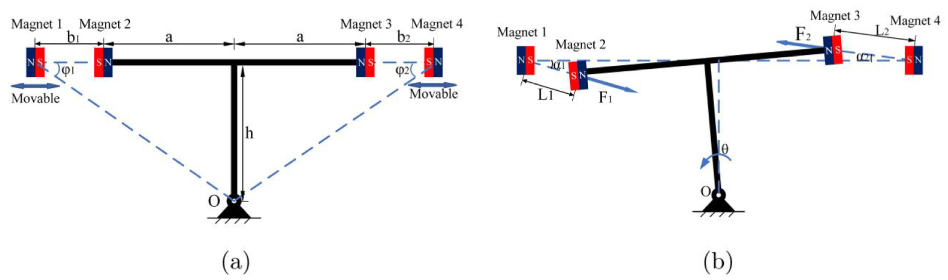
Schematic of the magnetic NSM: (a) the mechanism in its initial equilibrium position and (b) the mechanism rotated by an angle θ.
In Figure 1(a), the repulsive forces between the two pairs of magnets are exactly equal, and positioning all four magnets along the same line, a state referred to as the initial equilibrium position of the Magnetic NSM. In Figure 1(b), when rods a and h rotate by an angle θ, the distances between the two pairs of magnets become L1 and L2, respectively. The two pairs of magnets generate repulsive forces F1 and F2 respectively. The torques generated by these forces around the rotation center O can be derived by differentiating with respect to the rotation angle θ, which yields the rotational stiffness of the mechanism. Adjusting the distances between the movable magnets allows for changes in the mechanism’s rotational stiffness.
Magnetic force calculation
The calculation of magnetic forces between two cylindrical magnets is complex and challenging, making the identification of a simple yet accurate method for calculating magnetic forces important. The method for calculating magnetic forces adopted in this paper is derived from Akoun and Yonnet, 30 Ravaud et al., 31 and Janssen et al. 32 with further refinement and simplification by Robertson et al. for determining the forces and torques.18,24,33 Robertson also provided a Matlab script 34 for calculating magnetic forces, which has been utilized in the calculations for this study.
To simplify the calculation of magnetic forces in the Magnetic NSM Model, as shown in Figure 2, the two-dimensional magnetic force model is simplified to a one-dimensional model. D x and D y represent the distances between two magnets in the X and Y directions, respectively. The accuracy of this simplified calculation method has been verified in Zhu et al. 18 When D x ≫ D y as shown in Figure 2(a), the magnetic force between two opposing cylindrical magnets in the X and Y two-dimensional plane can be simplified to the coaxial magnetic force at the same position, as shown in Figure 2(b). The model, before simplification, requires separate calculations for the forces F x and F y in the X and Y directions. In contrast, this simplified one-dimensional approach only necessitates modeling the coaxial magnetic force (F mag ) using the method described in Robertson et al. 33

where the intermediate expression is
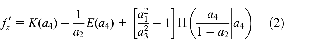
where

where r1 and r2 represent the radii of Magnet 1 and Magnet 2, respectively. The coordinate z1 denotes the position along the axis of the face of Magnet 1 that is farthest from Magnet 2, while z2 is the coordinate of the face of Magnet 1 closest to Magnet 2. Similarly, z3 represents the coordinate of the face of Magnet 2 closest to Magnet 1, and z4 indicates the position along the axis of the face of Magnet 2 that is farthest from Magnet 1. The functions K(m), E(m), and Π(m) correspond to the complete elliptic integrals of the first, second, and third kinds, respectively. J1 and J2 are the magnetizations in Tesla of the magnets in the positive z direction, μ0 = 4π × 10−7 N A−2.
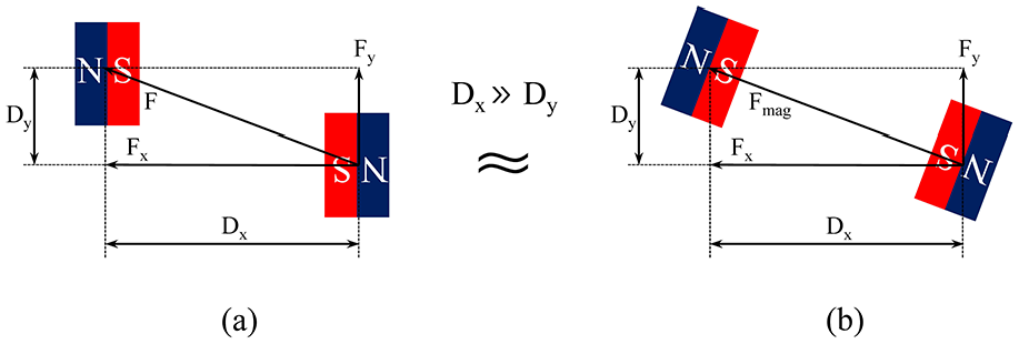
Magnetic force between two cylindrical magnets: (a) two-dimensional calculation model and (b) one-dimensional calculation model.
F mag is then projected onto the X and Y axes to determine the component forces F x and F y .


The theoretical calculations in this study are based on the following assumptions:
Calculation of torque
In the design of the Magnetic NSM, it is necessary to accurately calculate the relationship between the rotational angle θ of the mechanism and the torques M generated by the magnetic forces F1 and F2 between the magnets, in order to obtain the torque model of the magnetic NSM.
After the mechanism rotates by an angle θ, the distance L1 between magnet 1 and magnet 2 can be obtained by the cosine theorem in equation (6).

The angle α1 between the magnetic force F1 and the horizontal line, for magnets 1 and 2, is:

Considering the restorative torque in the direction opposite to angle θ as positive, the lever arm d1 of F1 relative to the rotation center O is:

Therefore, the torque M1 exerted by F1 on the rotation center O is:

Where F mag (L1) refers to the magnetic force calculation method described in the previous subsection, using the calculation method found in Robertson et al. 33 for the magnetic force when the distance between the centers of the two magnets is L1.
Following the same principle, the torque M2 exerted by the magnetic force F2 between magnets 3 and 4 on the rotation center O is:

The resultant torque M on the rotation center O from forces F1 and F2 is equation (11):

Where:
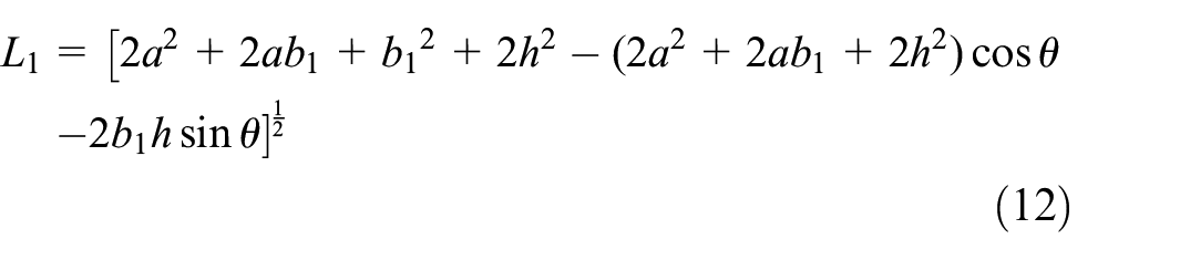

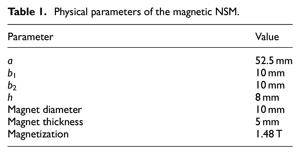
Figure 3 shows the torque and rotational stiffness graph for the magnetic NSM, calculated using equation (11) and based on the physical parameters listed in Table 1. Four identical cylindrical magnets with a magnetization strength of 1.48 T were used. The slope of the torque M tangent is the rotational stiffness k of the mechanism. It can be observed from the graph that at the initial equilibrium position of θ = 0°, the torque is zero, but the minimal (numerically smallest) stiffness achievable is k = −3.64 N m/rad. The mechanism exhibits negative stiffness within a ±5° range, meaning the direction of the generated torque is the same as the direction of rotation, indicating that the designed magnetic NSM successfully achieves negative stiffness.

Torque and rotational stiffness diagram of magnetic NSM.
Physical parameters of the magnetic NSM.
Structural and nonlinear analysis
The magnetic NSM model was established in the previous section. Based on this model, this section conducts structural dimension analysis and nonlinear analysis. The purpose of this section is to introduce the analysis of various structural dimensions, informing readers how to design a magnetic NSM mechanism whose negative stiffness magnitude meets design requirements and whose linear range is sufficiently large to cover the working range of the mechanism.
Structural dimension analysis
The magnetic NSM has multiple structural parameters, and it is necessary to study the impact of each structure dimension on the torque, which is informative for the design of various structural dimensions of the mechanism. By employing a controlled variable method, as shown in Figures 4 and 5, only one variable is changed at a time, while other variables remain constant as shown in Table 1. It is important to note that in Figures 4 and 5, within the M − θ plane, when the slope of the tangent to the M − θ curve is negative, it exhibits negative stiffness.

The impact of structural dimensions on torque: (a) the impact of a on torque and (b) the impact of h on torque.

The impact of structural dimensions on torque: (a) the impact of b on torque and (b) the impact of magnetization on torque.
As shown in Figure 4(a), the impact of the structural dimension a on the mechanism’s torque is illustrated. It can be observed from the figure that as a increases, the absolute value of the slope of the M − θ curve’s tangent gradually increases, implying that the negative stiffness progressively increases. The negative stiffness is minimal when a = 0.
As illustrated in Figure 4(b), the impact of the structural dimension h on the mechanism’s torque is shown. It can be observed from the figure that as h increases, the absolute value of the slope of the M − θ curve’s tangent gradually decreases. The impact of h on stiffness is relatively small.
As shown in Figure 5(a), where b = b1 = b2, the impact of the structural dimension b on the mechanism’s torque is illustrated, with b representing the distance between a pair of magnets at the initial equilibrium position. It can be observed from the figure that as b gradually decreases, the absolute value of the slope of the M − θ curve’s tangent gradually increases, indicating that the mechanism’s negative stiffness progressively increases. Under different values of parameter b, it can be observed from the figure that the smaller the value of b, the faster the slope increases. This is because the magnetic force increases sharply when the two magnets are very close to each other. Therefore, reducing parameter b is an effective method to enhance the negative stiffness of the NSM. However, this approach also has the drawback of increasing the nonlinearity of the stiffness. Additionally, when parameters b1 and b2 are not equal, an initial torque is generated at the equilibrium position. This initial torque can counteract the torque generated by the FSM’s own weight when it is installed in a non-horizontal position, allowing the static equilibrium position of the FSM to be corrected.
As illustrated in Figure 5(b), the impact of the magnetization strength of permanent magnets on torque is shown. When the magnetization strength is positive, indicating that a pair of magnets repel each other, the mechanism exhibits negative stiffness. Moreover, as the magnetization strength increases, the absolute value of the slope of the M – θ curve’s tangent gradually increases, meaning the negative stiffness progressively increases. On the contrary, when the magnetization strength is negative, indicating that a pair of magnets attract each other, the mechanism exhibits positive stiffness. Furthermore, as the absolute value of the magnetization strength increases, the slope of the M – θ curve’s tangent gradually increases, meaning the positive stiffness progressively increases. Therefore, by changing the magnetic poles between the two magnets, one can alter the mechanism to exhibit either positive or negative stiffness.
Overall, changes in the structural parameters a, b, and the magnetization strength have a significant impact on the stiffness of the mechanism, while h has a smaller effect. The stiffness of the mechanism can be relatively easily altered by changing the parameter b, that is, by moving magnets 1 and 4 to adjust b. Therefore, in this paper, the magnetic NSM employs the movement of magnets 1 and 4 to change the stiffness of the mechanism.
Specifically, by changing the magnetic poles, positive stiffness can be achieved, meaning that the stiffness variation range of the mechanism includes both positive and negative stiffness. Therefore, this mechanism can be applied not only as a component in quasi-zero stiffness systems formed by the parallel connection of negative and positive stiffness mechanisms but also in other systems requiring variable stiffness mechanisms. For example, the use of variable stiffness mechanisms in robotic joints can enhance human-machine interaction safety. 35 Hence, this mechanism has high practicality.
A comparison of different negative stiffness mechanisms is shown in Table 2 to better illustrate the advantages of our magnetic negative stiffness mechanism. The advantages of no contact friction, no parasitic high-frequency modes, and no stiffness nonlinearity have been detailed in the previous sections. The adjustable stiffness and equilibrium position facilitate adjustments during actual installation, thereby expanding the applicability of the magnetic negative stiffness mechanism.
Comparison of different NSMs.

Nonlinear analysis
Most existing NSMs typically exhibit significant stiffness nonlinear behavior. This degree of nonlinearity introduces complex nonlinear problems, increasing the complexity of system design and control, and greatly limiting the mechanism’s performance and application range. Compared to traditional NSMs, this mechanism, by achieving a wide range of linear stiffness adjustments, can significantly avoid nonlinear effects, exhibiting better performance and a broader application range.
In the previous subsection, the impact of various structural dimension on the mechanism’s torque is analyzed. Although changes in h have a very minimal impact on stiffness, the variation of h significantly affects the linearity of the mechanism’s torque. The mechanism’s linear range is represented as the area where the slope of the tangent to the rotational stiffness is zero, meaning the torque M generated by the mechanism is linearly related to the rotation angle θ. As shown in Figure 6, with other structural dimension parameters remaining constant as shown in Table 1, when h gradually increases from 8 to 24 mm, the linear range near θ = 0° first increases and then decreases. The rotational stiffness behaves such that when h = 19 mm, the mechanism’s rotational stiffness k = −2.84 N m/rad within a range of θ as ±1.07°, meaning the mechanism is linear within the ±1.07° range. Since the operating range of the FSM is within ±1°, applying the magnetic NSM to form a QZS system for the FSM results in a linear system.

The impact of h on the nonlinearity of the mechanism’s rotational stiffness.
Overall, by adjusting h, a larger linear range can be obtained at the expense of the magnitude of negative stiffness. To achieve a NSM with both larger negative stiffness and a larger linear range, other structural parameters can first be adjusted to achieve a stiffness greater than the targeted negative stiffness. Then, by adjusting h, the mechanism’s stiffness can be brought to the target negative stiffness while also increasing the linear range to exceed the target working range. Therefore, through detailed analysis of the structural dimensions mentioned above, readers can obtain a magnetic NSM that meets the target negative stiffness and has a sufficiently large linear range.
Experimental validation
The experimental schematic diagram for applying the magnetic NSM to a FSM is shown in Figure 7, where the NSM is installed on both sides of the FSM’s flexible hinge, with the rotation center of the NSM coinciding with the rotation center of the flexible hinge at point O. The experiment uses a frequency response test method, with the test signal generated by the DSP6747 microcontroller, amplified by a power driver, and then driving the voice coil motor to generate excitation forces. Two voice coil motors are placed opposite each other, centered around the flexible hinge, generating two excitation forces F m 1 and F m 2 of the same magnitude but opposite direction. Therefore, F m 1 and F m 2 form a couple, producing a driving torque on the rotation center O, causing the flexible hinge to rotate by an angle θ, which in turn causes the mirror to rotate by an angle θ. The eddy current displacement sensor can measure the rotation angle θ, and the DSP6747 can transmit the data to a computer for data analysis.
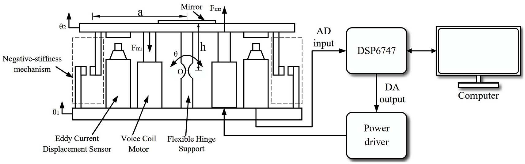
Schematic diagram of the experimental setup for applying the magnetic NSM to a FSM.
Magnetic NSM validation experiment
The magnetic NSM was installed on a FSM to verify the accuracy of the NSM principle. The microcontroller used in the experiment is the DSP6747 produced by Texas Instruments, USA. The model of the voice coil motor is TMEC0015-005-000, manufactured by TM motion company in China. The eddy current displacement sensor model is RS9000JXL, produced by RVIS company in China. Two magnetic NSMs are installed on the FSM, therefore, double the negative stiffness can be generated. Magnets 1 and 4 can be repositioned by rotating a lead screw, thus changing the gap between each pair of magnets and achieving different levels of negative stiffness.
The experiment employs a sinusoidal excitation force method by FSM’s voice coil motors, as shown in Figure 7, with the excitation forces F m 1 and F m 2 generated by the voice coil motors driving the mirror to produce a rotation angle θ. The mechanical equation for the experiment is:

Where J is the rotational inertia of the mechanism, c is the rotational damping of the mechanism, k is the stiffness of the magnetic NSM, k h is the stiffness of the flexible hinge, and M m is the excitation torque generated by the voice coil motors. To facilitate dimensionless processing, multiply by (k + k h ) on the right side of the equation. Applying the Laplace transform to equation (14) yields the transfer function:

Where the damping ratio
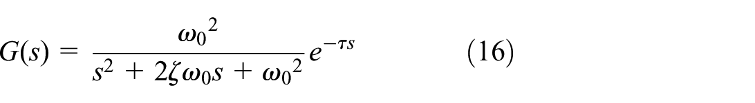
Where τ is the time constant of the delay element. τ = 5 × 10⁻⁴ s.
As shown in the frequency sweep test results in Figure 8, with experimental parameters as listed in Table 3. Initially, a frequency sweep test is conducted on the FSM without the magnetic NSM installed, and fitting of the experimental results yields a stiffness of the flexible hinge, k h = 12.3 N m/rad. Then, a frequency sweep test is performed on the FSM with the magnetic NSM added, when h = 9 mm, and fitting of the results yields a total stiffness of the flexible hinge and the magnetic NSM, k + k h = 0.3 N m/rad. Therefore, the stiffness of the magnetic NSM is k = −12 N m/rad.

Frequency sweep test results and fitting of the FSM before and after the installation of the magnetic NSM: (a) amplitude-frequency characteristic and (b) phase-frequency characteristic.
Experimental parameters for the magnetic NSM.

When we rotate the screw in Figure 9, we can change the gap between a pair of magnets, that is, alter the structural parameter b, while keeping other parameters consistent with those shown in Table 3, the magnetic NSM can achieve different stiffness values. Frequency sweep tests were conducted on the FSM for different b, yielding varying stiffness results for the magnetic NSM. The experimental results are illustrated in Figure 10, where the theoretical values are calculated based on the torque model.

Experimental setup of the magnetic NSM applied to a FSM.

Experimental and theoretical stiffness of the magnetic NSM.
Equation (17) is a statistical metric used to measure the accuracy of the theoretical model, where R2 is the coefficient of determination.

Where y
i
represents the experimental values,
Vibration isolation experiment of the QZS FSM
In the validation experiment of the magnetic NSM detailed in the previous subsection, the addition of the magnetic NSM to the FSM successfully reduced its stiffness from 12.3 to 0.3 N m/rad, achieving quasi-zero stiffness. This section will describe the vibration isolation experiment of the QZS FSM and discuss the results.
The vibration isolation effectiveness of an isolator is assessed by the attenuation efficiency in terms of displacement. As illustrated in the schematic diagram of the experimental setup shown in Figure 7, the vibration input to the base of the FSM is the angle θ1 and the vibration transmitted to the mirror surface is the angle θ2. The greater the attenuation of angle θ2 relative to angle θ1, the better the attenuation performance of the quasi-zero stiffness FSM.
During the experiment, a sinusoidal sweep frequency vibration input of θ1 was generated by vibration excitation motors in Figure 9 at the base of the FSM, and the absolute vibration output θ2 at the mirror surface was recorded. The analyzed experimental results are shown in Figure 11. When the structural parameter b = 9 mm of the magnetic NSM, the FSM achieved a quasi-zero stiffness of 0.3 N m/rad. Without the magnetic NSM installed, the vibration resonance frequency was 34.2 Hz, with a vibration amplitude of 20.1 dB. However, after incorporating the magnetic NSM to achieve QZS, the vibration amplitude was reduced from 20.1 to −12.8 dB, greatly reducing the transmission of vibration. Additionally, the lowest vibration frequency that could be suppressed was reduced from 54.63 to 3.44 Hz, significantly increasing the vibration suppression bandwidth across the frequency domain.

Frequency domain comparison of vibration isolation effect before and after the FSM achieved QZS: (a) amplitude-frequency characteristic and (b) phase-frequency characteristic.
As shown in Figure 12, the time-domain comparison of the vibration isolation effect before and after the FSM achieved QZS. The amplitude recorded in the figure is in terms of the voltage of the eddy current displacement sensor, where 1 V voltage corresponds to 1.11 mrad of angular displacement. In both scenarios, the input vibration used has the same amplitude, with a frequency of 34.2 Hz. The FSM, without the magnetic NSM, “amplifies” the input vibration displacement to 10.1 times its original value, whereas the vibration output of the QZS FSM with the magnetic NSM added attenuates to 22.9% of its original value.
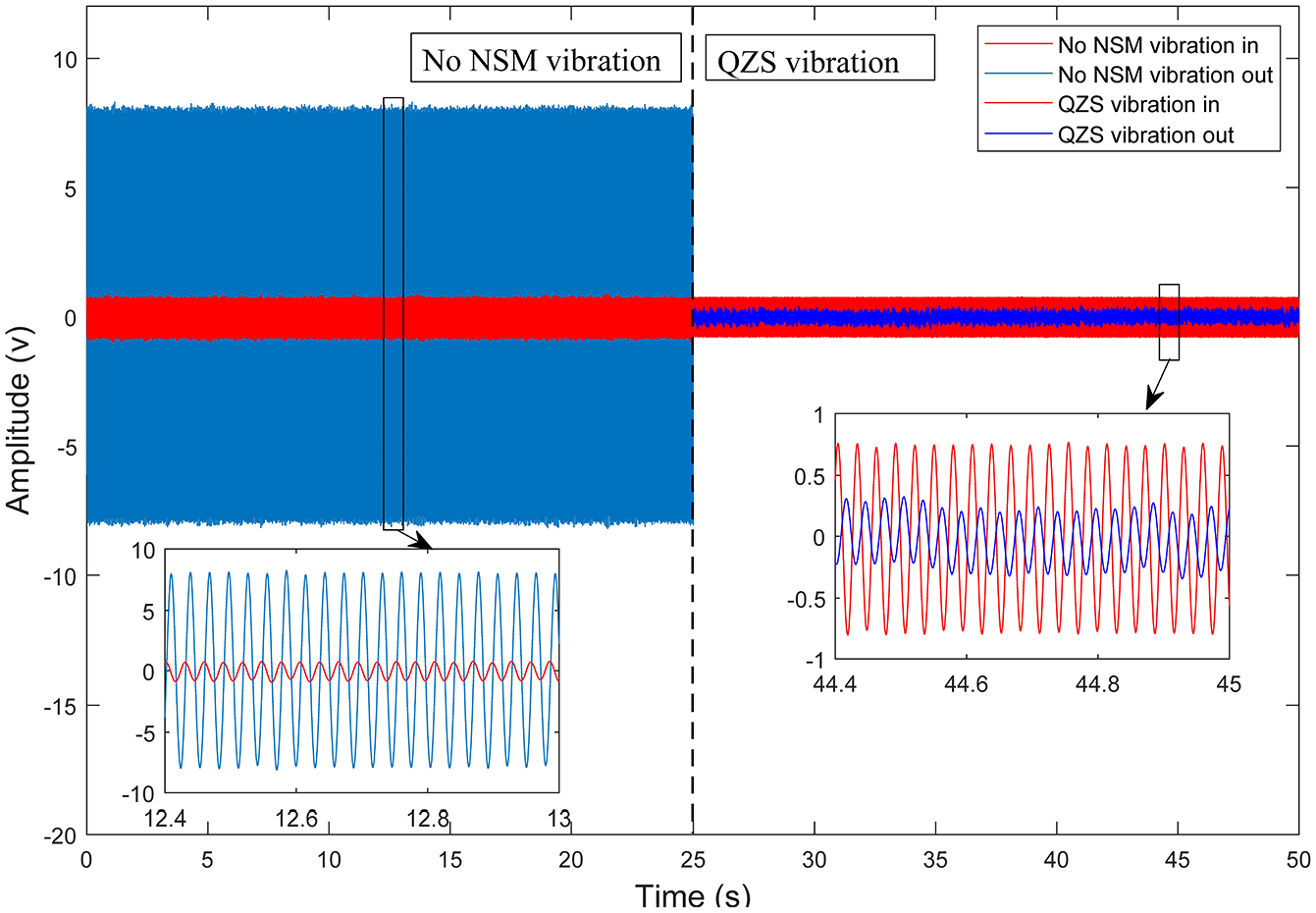
Time-domain comparison of vibration isolation effects before and after the FSM achieved QZS.
For the magnetic NSM proposed in this paper, experiments were designed to validate the accuracy of the mechanism’s principles. Figure 10 shows the agreement between the theoretical stiffness and the experimentally obtained stiffness. The designed magnetic NSM was then integrated into the FSM for further experimentation. Figure 8 presents the frequency sweep results of the QZS FSM after the stiffness was reduced. Finally, Figures 11 and 12 demonstrate the vibration isolation effects in the frequency domain and time domain, respectively.
In summary, the FSM achieving QZS significantly enhances the vibration suppression bandwidth while suppressing the resonance peak, especially addressing the lowfrequency vibration suppression issue that is challenging for general isolators. This constitutes an exceptionally superior vibration isolation design. The vibration isolation performance of the FSM is greatly improved.
Conclusion and future work
This paper introduces a magnetic NSM, applied to a FSM to achieve QZS for vibration isolation as a case study. The magnetic NSM can achieve a negative, adjustable rotational stiffness, and effectively mitigates issues commonly associated with mechanical spring-based NSMs, such as contact friction, parasitic high-frequency modes, and stiffness nonlinearity. With appropriate structural dimension parameter combinations, the mechanism can meet the design requirements of sufficiently large negative stiffness and a sufficiently broad linear range. The theoretical model of the magnetic NSM was validated by experimental results, with a coefficient of determination R2 = 0.998, fully verifying the accuracy of the magnetic NSM principle.
When the magnetic NSM is applied to the FSM, stiffness is significantly reduced from 12.3 N m/rad to quasi-zero stiffness at 0.3 N m/rad. This adjustment results in a decrease of the resonance peak from 20.1 to −12.8 dB, and lowers the minimum suppressible vibration frequency from 54.63 to 3.44 Hz. Such modifications substantially broaden the vibration isolation bandwidth in the frequency domain and enhance the effectiveness of vibration isolation. The QZS FSM overcomes the challenge of low-frequency vibration isolation that conventional isolators struggle with, embodying an exceptionally superior vibration isolation design.
This research opens several avenues for future investigation. First, while our new magnetic NSM has demonstrated significant improvements in vibration isolation for FSM, further studies could explore its application in other precision mechanical systems, such as high-precision manufacturing equipment or space-based telescopic systems. Additionally, the scalability of the NSM for larger systems and its integration with active control strategies could be examined to enhance its effectiveness in more dynamic environments. Future research could also focus on optimizing the magnetic configuration to achieve even lower stiffness and broader isolation bandwidths, thereby pushing the limits of vibration isolation technology.
Footnotes
Handling Editor: Aarthy Esakkiappan
Declaration of conflicting interests
The author(s) declared no potential conflicts of interest with respect to the research, authorship, and/or publication of this article.
Funding
The author(s) disclosed receipt of the following financial support for the research, authorship, and/or publication of this article: National Natural Science Foundation of China (Grant No. 62271109).