
Abstract
Load sensing technology is a typical hydraulic technology that automatically meets load requirements by adjusting the pressure and flow at the pump outlet. Traditional load sensitive pump control systems rely on variable mechanisms to achieve such flow control characteristics. However, general variable mechanisms have complex structures and poor dynamic performance if frequently adjusted. Therefore, a new variable mechanism, named two-dimensional pulse width modulation rotary valve, is proposed. Different from the pulse width modulation control method of the electronic technology, the two-dimensional pulse width modulation rotary valve conducts secondary distribution of the quantitative pump output in the way of fluid pulse width modulation: the valve core rotates to generate discrete fluid, and the axial sliding of the valve core controls the duty ratio of the discrete fluid. The dynamic balancing of the axial displacement is controlled by feedback pressure to provide a fixed differential pressure for the control valve, achieving that the flow through the control valve is uniquely controlled by the valve opening of the control valve. The principle of the fluid pulse width modulation is first introduced, and then the mathematical model of the proposed variable mechanism and the corresponding system is established. Simulation analysis is implemented. Finally, the effectiveness of the load sensing system controlled by a two-dimensional pulse width modulation rotary valve is verified by the experiment.
Introduction
Load sensing technology is a key technology in the hydraulic field, which automatically senses the pressure, flow or power demand of the system and only provides the flow or pressure required of the system to meet the power requirements of the system. The load sensitive control system has the characteristics of elevated efficiency (considerably higher than the conventional hydraulic system) and low power loss, which means fuel saving and low heating capacity of the hydraulic system. There are many factors that affect the efficiency of the hydraulic system, 1 so there should be many solutions to improve the efficiency of the hydraulic system, load sensitivity is one of ideal design schemes which is widely used in various fields such as engineering machinery, aerospace, weapons, and equipment.2–4
At present, the relatively common load sensing system is the combination of load sensing plunger pump and load sensing control valve,5,6 which enables the entire hydraulic system to be supplied with the appropriate pressure and flow rate for the load required. When the system is in operation, the pressure compensator of the variable piston pump can sense the flow demand of the system and provide adjustable flow according to the flow demand caused by the change of system conditions. Here, a control valve with a special sensing oil circuit and valve port is required to transmit the pressure signal to the variable piston pump,7,8 because the working pressure of the hydraulic system is different when the external load changes (most hydraulic systems cannot operate under constant pressure). As a result, the pump responds to the pressure demand of the hydraulic system, ultimately achieving the complete control of the load sensing system.
Traditional load sensitive pump control systems rely on variable mechanisms to achieve load sensitive control characteristics. Therefore, in order to achieve excellent load sensitive control characteristics, numerous scholars have conducted structural optimization of the variable mechanism, optimized parameter matching, or proposed new variable mechanisms for the displacement control of load sensitive pumps. In addition, some researches have been developed on the design of load sensitive hydraulic circuits and corresponding control methods.
In terms of optimizing the structure of the variable mechanism of load sensitive pumps, some scholars have studied the inherent characteristics of load sensitive pumps. Liu et al. 9 focused on the pressure shock characteristics of load sensitive pumps and studied the impact of pressure shock characteristics under different load conditions. More attempts have been devoted to investigating the mapping relationship between the structural parameters of the variable mechanism and load sensitive control characteristics. Jiao et al. 10 established a nonlinear multi-parameter model to study the influence of load sensitive pump structural parameters on flow characteristics. Zhang et al. 11 established an intuitive physical model of load sensitive pumps using Amesim software. Through simulation, the effects of structural parameters such as spring stiffness and valve core diameter of load sensitive valves on the dynamic characteristics of load sensitive pumps were studied, providing a theoretical value basis for the design and use of load sensitive pumps. Based on the study of the influence of the variable mechanism structural parameters on control characteristics, some scholars have optimized the structure of the variable mechanism. Cui et al. 12 proposed a structural optimization method based on the dynamic model of load sensitive pumps. This method was validated through simulation and experiments, and achieved the goal of improving the dynamic performance of load sensitive pumps. Wang et al. 13 focused on analyzing the impact of matching parameters of variable mechanisms on flow control accuracy, through the study, proper load-sensitive valve and pressure shut-off valve radial fit clearance and load-sensitive valve port negative cover were obtained, which improved the flow control accuracy of load-sensitive pump control system and reduced losses.
Other scholars have innovated variable mechanisms, Huang et al. 14 designed a pressure assist valve in the variable mechanism of a load sensitive pump to actively sense changes in load pressure and apply the changed pressure to a variable cylinder, thereby achieving control of pump displacement. Chao et al. 15 proposed a load sensing pump specifically designed for the electro-hydrostatic actuator, which works together with a spool valve and a linear spring to modify the pump’s volumetric displacement. To avoid the need for additional power, the self-powered volumetric flow rate is taken from the pump’s output flow rate and then acts on the spool valve to drive the swashplate, which can automatically adjust its volumetric displacement with the load pressure.
Numerous attempts have been devoted to matching the design of load sensitive hydraulic circuit. Siebert et al. 16 proposed a new type of load sensitive system. In the hydraulic circuit, each actuator part is automatically connected to the tank or hydraulic accumulator through an additional valve, which enables the system to achieve load sensitive function while reducing the throttle pressure difference of the pressure compensator. In addition, some scholars have also proposed different ideas on how to achieve load sensitivity. Fassbender et al. 17 proposed a new load sensing system using motor variable control. Different from traditional load sensing systems, in the new system, the motor torque is automatically controlled to provide the required pressure to the load, and the motor speed is adjusted to control the speed of load movement. Ding et al. 18 changed the traditional hydraulic circuit connection method based on independent control of the load port to expand various energy-saving working modes, including load sensitivity.
For the existing control methods for load sensitive systems, Cheng et al. 19 proposed a multi-mode electro-hydraulic load sensing (MELS) control method that achieves pressure, power, and load sensing control functions. Song et al. 20 proposed a hybrid adaptive quantum particle swarm optimization algorithm for load sensing system of hydraulic excavator to adjust the parameters of the proportional integral derivative controller, which improved the trajectory control accuracy of the excavator actuator. Ding et al. 21 proposed a load sensitive synchronization control method that achieves precise synchronization in open-loop control. Compared with traditional synchronization valve control, this method has higher synchronization accuracy in load sensitive synchronization control. In addition, scholars have also designed new control methods to improve the energy-saving effect of load sensitivity. Tian et al. 22 proposed two control schemes: variable pump margin (VPM) and mixed variable margin (HVM) in order to achieve additional energy saving than traditional method.
In addition, some new structures of valves have been proposed for distributing system flow or pressure. Tu et al. 23 proposed a new high-speed on-off valve with a rotating valve core, which can use the oil flowing through the valve as a hydraulic source to drive the valve core to rotate; Jia et al. 24 proposed a two-dimensional high-frequency rotation direction control valve with two degrees of freedom: axial linear motion and circumferential rotation, and studied the steady-state and transient flow torque generated by the valve; Xu et al. 25 proposed a two-dimensional pulse width modulation rotary valve and demonstrated its pulse width modulation function through simulation experiments. Moreover, the system can also control the quantitative pump through the hydraulic valve to achieve load sensitive functions, such as proportional valves, digital valves, etc. Bury et al. 26 proposed the combination of proportional solenoid valve and quantitative pump, through the proportional solenoid valve to distribute flow to the quantitative pump, to achieve load sensitive function. However, the combination of proportional valve and quantitative pump can cause significant overflow loss and relatively low efficiency.
The variable mechanism of traditional pump controlled load sensing systems usually refers to the displacement control mechanism of the inclined plate. However, the variable mechanism is relatively complex and its response speed is not high.27,28 If the dual variable adjustment (variable speed of the motor and variable displacement of the hydraulic pump) is frequent, it will lead to relatively poor dynamic performance. Therefore, this paper presents a new variable mechanism applied to the hydraulic power system to realize load sensitivity.
The two-dimensional pulse width modulation rotary valve has been designed, so the purpose of this paper is to develop a new system combining rotary valve and quantitative pump to realize load-sensitive functions. Based on the working principle of fluid pulse width modulation, the dynamic pressure balance at both ends of the speed control valve is achieved to obtain load sensitive function and load sensitive control characteristics. The research results can provide a way for distributed independent power sources to be applied to complex hydraulic systems with multiple operating conditions and execution units.
Working principle
Two-dimensional rotary valve concept
As shown in Figure 1, the two-dimensional pulse width modulation rotary valve mainly consists of valve core, valve sleeve, valve body, and other components. There are two rows of staggered triangular grooves on the shoulder of the valve core, with their vertices in the same plane, which is perpendicular to the axis of the valve core. Here, one row is for port A (oil inlet), and the other row communicates with port T (oil return). Correspondingly, the diamond shaped windows are evenly distributed on the valve sleeve. The triangular groove of the valve core is matched with the diamond shaped window of the valve sleeve to form a parallelogram valve port. When the valve core rotates continuously and slides axially, this geometric arrangement causes periodic changes in the throttling area formed by the valve core groove and the valve sleeve window.
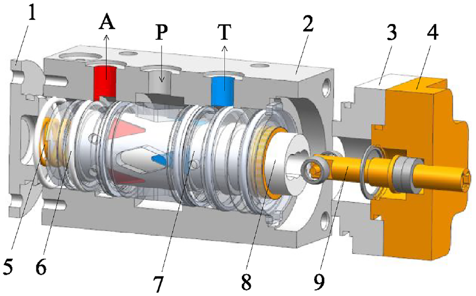
A three-dimensional model of a two-dimensional pulse width modulated rotary valve. (1) Distribution end cover, (2) valve body, (3) switching block, (4) bearing, (5) spring, (6) sealing ring, (7) valve sleeve, (8) valve core, and (9) drive shaft.
Different from the traditional method of electronically controlling the duty ratio of high-speed electromagnetic on-off valves, the two dimensional pulse width modulated rotary valve can adjust the fluid pulse width through the axial displacement of the valve core because of the mechanical structure and matching relationship between the valve core and the valve sleeve, and realize the flow control and distribution.
Fluid pulse width modulation concept
The cylindrical valve core of the proposed two-dimensional pulse width modulation rotary valve has two non-interacting degrees of freedom, namely circumferential rotation and axial sliding, within the valve sleeve. The circumferential rotation of the valve core is driven by a motor. With the two-dimensional movement of the valve core, the two rows of grooves of the valve core alternate with the valve sleeve windows to form a load port (A port) and a return port (T port), the valve port can quickly “open” (connected to the load) –“close” (connected to the tank); the valve core slides to achieve the time ratio of “opening” to “closing” of the control valve port. For convenience of view, rotating the valve sleeve here does not affect the relative position relationship between the valve core and the valve sleeve. Taking Figure 2 as an example, the valve sleeve is located in the middle position of the valve core (if the plane is unfolded), and the duty cycle at this position is 50%. In two-dimensional rotary valves, the design of valve ports with special shapes is mainly aimed at obtaining a sufficiently large area gradient to reduce the throttling loss of the valve port, especially during the opening and closing processes.

Valve core and valve sleeve plane matching with duty ratio of 50%.
The valve core rotates to realize fast and high frequency switching between the load branch and the tank to output discrete flow, the valve core moves axially to control the duty ratio to achieve the control of the output average flow. Therefore, the two-dimensional pulse width modulation rotary valve serves as a flow distribution mechanism, distributing flow in the form of fluid pulse width modulation: supplying the required flow of the system to the load, and excess flow returning to the tank through active overflow, as shown in Figure 3.

Flow distribution diagram with duty ratio equal to 50%.
When the axial displacement of the valve core slides downwards (from a plane perspective), the communication time between the valve sleeve window and the valve core groove connected to port A is longer than that of the valve port groove connected to the return port, forming a fluid pulse width modulation wave with a duty ratio greater than 50%, as shown in Figures 4 and 5.

Valve core and valve sleeve plane matching with duty ratio >50%.

Flow distribution diagram with duty ratio >50%.
Load sensitive pump system
The new load sensitive circuit is shown in Figure 6, mainly composed of the proposed two-dimensional pulse width modulation variable mechanism, quantitative pump, speed control valve, and loading hydraulic cylinder. Here, the loading hydraulic cylinder is used to simulate various hydraulic actuators used in actual equipment applications. The speed control valve is used to receive speed regulating command signals and convert the operator’s control intention into the valve opening signal. The expected flow control characteristic of this circuit is that the flow through the speed control valve is only controlled by the valve opening of the valve. By changing the opening of the speed control valve, the speed of the hydraulic actuator can be accurately controlled.

Schematic diagram of load sensing system.
The load sensitive system relies on variable mechanisms to achieve the aforementioned flow control characteristics. The variable mechanism of traditional load sensitive pump control systems is generally composed of load sensitive valves, pressure shut-off valves, and bypass throttling ports. In this paper, the variable mechanism is a two-dimensional pulse width modulation rotary valve. The proposed two-dimensional pulse width modulation rotary valve has a high-pressure oil chamber on the left and a control oil chamber on the right. It senses the outlet pressure of rotary valve and load pressure on both sides of the valve core, and compares its pressure difference with the spring pressure set at the left end of the valve core (about 1–2 MPa). If the pressure difference is greater than the spring set pressure, the valve core will move to the left, the duty ratio decreases, the flow into the load port decreases, causing more high-pressure oil at the pump outlet to enter the variable mechanism, and the pressure drop through the speed control throttle valve will increase accordingly.
On the contrary, if the pressure difference between the outlet pressure of rotary valve and load pressure is less than the spring set pressure, valve core will move to the right, the duty ratio increases, the flow into the load port increases, resulting in a decrease in the pump output flow and in pressure drop through the speed control valve. Using the feedback process mentioned above, the pressure drop at both ends of the speed control valve always tends to be dynamically constant.
Mathematical modeling
Duty ratio
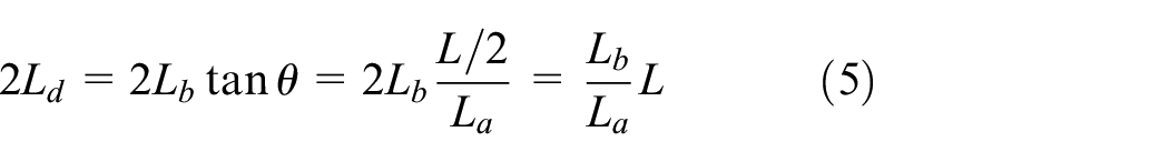
The axial displacement of the valve core can control the communication time between the valve port and the load branch, as well as the communication time with the return branch, thereby achieving control of the average output flow rate. Figure 7 shows the circumferential expansion diagram of the valve core and valve sleeve of the two-dimensional pulse width modulation rotary valve within one cycle. The bottom edge of the valve core triangular groove is defined as L. The height of the triangular groove is defined as La, which is also the maximum displacement of the axial displacement of the valve core. Lb is the spool axial displacement length. 2Ld represents the circumferential displacement of the single-row valve core triangular groove communicating with the valve sleeve window. The top angle of the triangular groove is 2θ, and the top angle of the valve sleeve diamond window is also the same.

Circumferential expansion diagram of valve core and valve sleeve.
The rotation of the valve core is driven by an electric motor, and the angular velocity of the valve core rotation is

where ω is the angular velocity of the valve core rotation and n1 is the motor speed.
From the moment of critical communication between the triangular groove of the valve core (connected to port A) and the valve sleeve window to the moment of close communication between the triangular groove of the valve core (connected to port T) and the valve sleeve window, it is defined as a cycle of change in the throttle area of the valve port.

where T1 is the cycle of change in the throttle area of the valve port, NA represents the number of diamond shaped windows in the two-dimensional pulse width modulation rotary valve sleeve and also the number of triangular grooves in a single row of valve cores.
The communication time between the single row valve core groove (connected to port A) and the valve sleeve window is defined as tA.

where r is the radius of the valve core.
The “duty ratio” of fluid pulse width modulation is defined as the ratio of the communication time of the load branch to the total communication time of the load and return branch when the valve core is at a constant speed.

where x is the duty ratio of fluid pulse width modulation.
Here, Ld can be derived as
The ratio of the axial displacement of the valve core to the height of the single row triangular groove of the valve core is defined as e.

So equation (5) can be rewritten as

And the bottom edge of the valve core triangular groove is expressed as
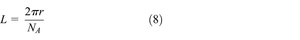
Substitute equations (1), (7), and (8) into equation (4) to obtain
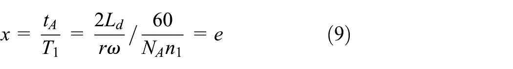
From this, it can be seen that the duty ratio of the two-dimensional pulse width modulation rotary valve is equal to the percentage of axial displacement of the valve core. By adjusting the axial displacement of the valve core, the duty ratio can be adjusted to adjust the flow output.
Rotary valve port area
As the valve core rotates and slides axially, the two rows of triangular grooves (connected to ports A and T, respectively) of the valve core alternate with the diamond shaped window of the valve sleeve to form a periodically changing throttling port area.
As shown in Figure 8, set the maximum valve port area for communication between the valve sleeve window and the single row triangular groove of the valve core (connected to port A) as the initial position, at which point, t = 0. The valve core rotates from left to right, and the valve port area gradually decreases from maximum to close, which is the first process of valve port change. The second process is the communication between the valve sleeve window and the single row triangular groove of the valve core (connected to the T-port), which changes until the final closure. The third process is to communicate again between the valve sleeve window and the single row triangular groove of the valve core (connected to port A), from opening to the maximum communication area.

Change in valve port area within a cycle.
When the duty ratio x is ≤50%, a throttling port is formed by the valve sleeve diamond shaped window and the valve core triangular groove (connected to port A), and it gradually decreases from maximum, as shown in Figure 9.
A throttling port gradually decreases from maximum when the duty ratio x ≤ 50%.
Judging from the geometric relationship in Figure 9, the expression for the area of the valve port can be derived as

where SA1 represents the gradually decreasing valve port area between the valve sleeve window and the valve core groove (connected to port A), represented by a shadow in Figure 9; Lc1 is the rotational distance of the valve core, Lh1 is the height used to calculate the shadow area SA1, which varies with the variation of Lc1, and t1 is the time it takes for the valve port to gradually decrease from its maximum area to its closure.
When the valve sleeve window and the single row triangular groove of the valve core (connected to port A) are connected again, the valve port area gradually increases from the opening to the maximum connected area, as shown in Figure 10.

A throttling port gradually increases from the opening to the maximum when duty ratio x ≤ 50%.
Similarly, the gradually increasing valve port area between the valve sleeve window and the valve core groove (connected to port A) is expressed as

where SA2 represents the gradually increasing valve port area, represented by a shadow in Figure 10; Lc2 is the rotational distance of the valve core during the process of gradually increasing the valve opening to its maximum, Lh2 is the height used to calculate the shadow area SA2, which varies with the variation of Lc2, and t2 is the time required for the valve opening to gradually increase.
When duty cycle x is greater than 50%, the analysis is similar to the case of less than or equal to 50%.
Valve core force balance
The shoulders of the valve core and the valve body form two closed chambers at both ends of the two-dimensional pulse width modulation variable mechanism. The right high-pressure chamber is filled with high-pressure oil, and the pressure in the left control chamber is the load pressure fed back by the load branch. Therefore, the end faces on both sides of the valve core can respectively feel the Outlet pressure of rotary valve and load pressure. The pressure difference between the two chambers and the spring work together on the valve core, as shown in Figure 11.
Force acting on the valve core of a two-dimensional pulse width modulation variable mechanism.
When the load pressure increases, the increased pressure is fed back to the control chamber, pushing the valve core to move to the right. This increases the duty ratio, causing more flow to flow into the load branch. In the meantime, the right movement of the valve core causes an increase in pressure in the high-pressure chamber. The pressure difference and spring work together on the valve core, and the valve core moves until the valve core is re-balanced; on the contrary, when the load pressure decreases, the valve core moves to the left, the duty ratio decreases, and the flow into the load branch decreases. Due to the left displacement of the valve core, the pressure in the high-pressure chamber will also decrease, and the valve core will move until it is balanced again. By utilizing the feedback process mentioned above, the pressure difference between the two ends of the valve core always tends to be dynamically constant. The force balance relationship acting on the valve core is expressed as follows.

where p2 is the pressure of the high-pressure chamber, which is connected to the outlet pressure of the pump; p1 is the control chamber pressure; S2 is the action area of the high-pressure chamber valve core; S1 is the action area of the control chamber valve core; F0 is the spring preload; mv is the valve core mass; xv is the displacement of the valve core (set to the right as positive); and Ks is the spring stiffness.
The valve core of the two-dimensional pulse width modulation variable mechanism is driven by a stepper motor for rotational motion, and the force equation of the valve core during the rotation process is expressed as

where Td is the motor torque, Jr is the rotational inertia of the motor rotor, and Jf is the rotational inertia of the oil, θ1 is the angular displacement when the valve core rotates, Bi is the damping coefficient of the transient hydraulic torque, Bf is the viscous friction coefficient between the valve core and the valve sleeve, Br is the damping coefficient of the motor rotor, and Kw is the steady-state hydraulic torque stiffness.
System modeling
A simplified model for the combination of a two-dimensional rotary valve and a quantitative pump is shown in Figure 12.

Model of load sensing system.
The constant flow rate of the quantitative pump output is Qp. When the flow enters the hydraulic line at the pump outlet, the compression effect occurs, and layer losses and local losses are ignored here. The pressure pi in the hydraulic pipeline at the pump outlet can be approximated as the pump outlet pressure, which is determined as
Where V is the volume of the hydraulic pipeline at the pump outlet, βi is the elastic modulus of the oil, QA is the flow rate into load port A, and QT is the flow rate into return port T.
The flow rate QA flowing into load port A can be expressed as

Where Cd is the flow coefficient, and SA is the effective area of port A valve port, ρ is the density of the oil, and pA is the pressure at the outlet of port A.
The flow rate QT flowing into the return port T can be expressed as
Where ST is the effective area of port T valve port and pT is the pressure at the outlet of port T.
After the flow flows out of the load port A and enters the hydraulic pipeline in front of the speed control valve, compression effect will also occur in this hydraulic pipeline, and the pressure pA here is determined as

Where VA is the volume of the hydraulic line in front of the speed control valve, Qleakage is the flow rate leaking from the load port A to the return port T, and QL is the flow rate out of the speed control valve.
The flow rate QL out of the speed control valve can be expressed as
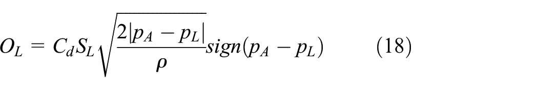
Where SL is the speed control valve area and PL is the speed control valve outlet flow rate.
After passing through the speed control valve, the flow enters the hydraulic pipeline before the load, and the pressure here is determined as

where VL is the volume of the hydraulic line after the speed control valve and QF is the flow rate required by the final load.
When the two-dimensional pulse width modulation rotary valve rotates continuously, the load port A continuously opens and closes within a cycle, as well as changes the flow area when adjusting the speed control valve. The fluid will generate inertia effects in the pipeline, and its pipeline flow rate is determined as
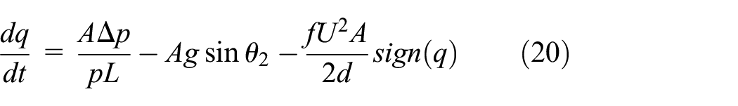
Where q is the flow rate entering the pipeline within time t, and A is the cross-sectional area of the pipeline, Δp is the pressure drop of the pipeline, g is the acceleration of gravity, θ2 is the horizontal inclination angle of the pipeline, f is the pipeline friction factor, U is the average fluid velocity, and d is the pipeline diameter.
Simulation
Simulation model
Amesim software was used to build the simulation model, as shown in Figure 13. Two piston chambers are simulated as control chambers and high-pressure chambers of a two-dimensional pulse width modulation rotary valve, with springs installed in the control chambers. The mass block is simulated as the valve core, the hydraulic cylinder is used to simulate the load in actual equipment, and variable throttle ports are used to simulate changes in valve orifice area by receiving speed control command signals. The throttle is used to simulate the speed control valve, and the hydraulic cavity is used to simulate the pipe. Here the safety valve mainly plays a protective role.

Load sensitive system simulation model.
The relevant parameters of the simulation model are detailed in Table 1.
Load sensitive system simulation model parameters.

Simulation results
Set the load pressures to 31,416, 54,978, 39,270, and 47,124 N, which are 40, 70, 50, and 60 bar, respectively, as shown in Figure 14, to simulate changes in load pressure. When the load changes, the pressure is fed back to the control chamber of the two-dimensional pulse width rotary valve. The pressure difference between the control chamber and the high-pressure chamber, as well as the spring force, jointly drive the valve core to move. As a result, the flow rate entering the load branch is changed by changing the duty ratio until the high-pressure chamber pressure and the control chamber pressure are re-balanced.

Characteristic curve of throttle differential pressure.
From Figure 14, it can be seen that the trend of changes in Outlet pressure of rotary valve and load pressure are basically the same. This indicates that when the load changes, the system can adjust accordingly based on the load feedback pressure, and the pressure difference between the Outlet pressure of rotary valve and load pressure is always stable at 16 bar, which is equal to the pressure difference set by the spring preload.
The valve opening setting of the speed control valve is shown in Figure 15, increasing from 0 to 0.8 (the ratio of valve opening to full opening) within 0–3 s, keeping the opening unchanged within 3–7 s, and decreasing from 0.8 to 0 within 7–10 s.

Change curve of valve port area ratio of speed control valve.
When the area of the speed control valve port changes as shown in Figure 15, the load pressure and Outlet pressure of rotary valve are obtained as shown in Figure 16. The two-dimensional pulse width modulation variable mechanism dynamically adjusts the axial displacement of the valve core through pressure difference feedback, so that the pressure drop at both ends of the speed control valve always tends to be dynamically constant. The pressure difference between the load pressure and the Outlet pressure of rotary valve remains unchanged and remains basically stable at around 16 bar.
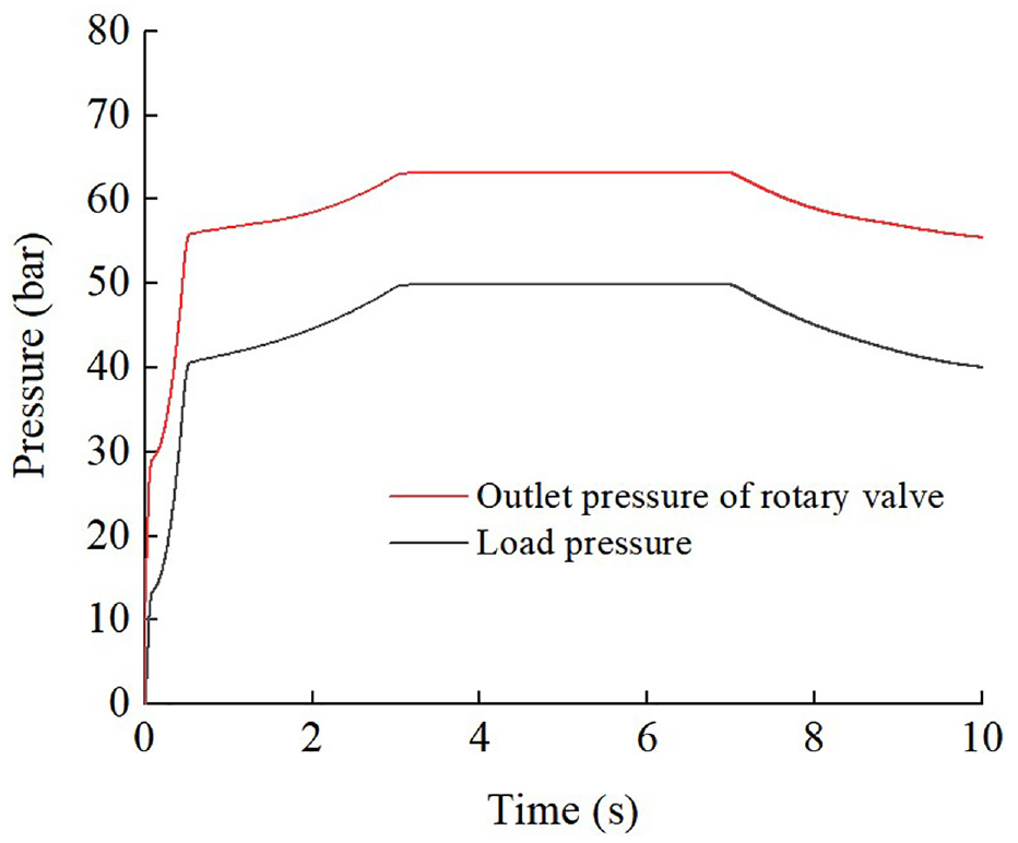
Pressure characteristic curve at both ends of the speed control valve port.
In the simulation model, by applying a control signal as shown in Figure 15 to the opening of the speed control valve, the flow through the speed control valve will be obtained as shown in Figure 17. It can be seen that the flow through the speed regulating valve is mainly controlled by the opening of the speed regulating valve. This indicates that the simulation model can effectively reveal the variable principle of the two-dimensional pulse width modulation variable mechanism, reflecting the load sensitivity characteristics of the new variable mechanism and the dynamic control process of flow.

Throttling port flow characteristic curve.
Experiment
Experimental hardware
Under the same conditions as the simulation model, the test bench was constructed to verify the load sensitive characteristics of the new variable mechanism and carry out corresponding flow dynamic control experiments. Based on Figure 6, a test bench is constructed as shown in Figure 18, mainly including quantitative pump oil source, two-dimensional pulse width modulation variable mechanism, a speed control valve, an actuator, and the controlling platform. Here, the pump station mainly provides flow to the system, the valve core of the two-dimensional pulse width modulation variable mechanism is driven by a stepper motor with a controller, the flow sensor is used to measure the flow through the speed control valve, and the pressure sensor is used to measure the load pressure and Outlet pressure of rotary valve respectively, this controlling platform is designed to control and monitor the entire experimental system, as well as collect, display, and process experimental data or results.

Load sensing system experimental platform.
Experimental results and discussion
Fluid pulse width modulation experiment
The output pressure of the two-dimensional pulse width modulation rotary valve at different speeds is shown in Figure 19, the green, yellow, and orange waveforms correspond to frequencies of 80, 120, and 160 Hz, respectively. In the experiment, the maximum rotation frequency of the rotary valve can reach around 200 Hz. The square wave characteristics in the diagram show that the rotary valve can pulsate the flow. The amplitude of the pressure pulse width modulated waveform can be determined by equation (14). The output pressure of the two-dimensional pulse width modulation rotary valve depends on the control pressure, which is set by a pressure servo valve in the experiment; the frequency of the pressure PWM wave is determined by the product of the relative velocity between the valve sleeve and valve core and the number of overflow windows on the valve core. The output pressure is maintained at around 16 MPa. When communicating with the T-port of the rotary valve, a certain pressure value is still present due to the setting of a certain backup pressure at the return port.
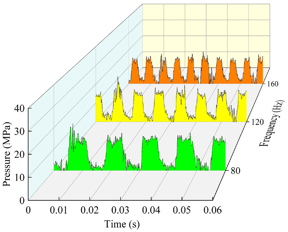
Time-pressure diagram at different frequencies.
The output pressure of the two-dimensional pulse width modulation rotary valve under different axial displacements is shown in Figure 20, with green, yellow, and orange waveforms representing pressure waveforms with duty ratios of 0.35, 0.5, and 0.65, respectively. The axial movement of the valve core changes the duty ratio of the output waveform and also changes the oil flow rate entering the hydraulic system.

Time-pressure diagram under different duty ratios.
The experimental results show that the two-dimensional pulse width modulation rotary valve can control and distribute the hydraulic system flow rate in a fluid pulse width modulation manner. The frequency of fluid pulse width modulation can be controlled by the rotation speed of the valve core, and the duty ratio can be controlled by the axial displacement of the valve core.
Load sensitivity experiment
The load sensitive characteristic test was conducted on the test platform. The outlet pressure of rotary valves and load pressures are obtained through a pressure sensor, and the results are compared with the simulation results, as shown in Figure 21. The experimental results are basically consistent with the simulation results. The outlet pressure of rotary valve and load pressure always tends to be dynamically constant. The pressure drop at both ends of the speed control valve always tends to be dynamically constant, and the pressure difference is about 16 bar.

Comparison of experimental and simulated Outlet pressure of rotary valves and load pressures.
For the same conditions as the simulation, a corresponding flow dynamic control experiment was conducted using the experimental platform, and the experimental results were basically consistent with the simulation results, as shown in Figure 22. The pressure drop at both ends of the speed control valve always tends to be dynamically constant (see Figure 21); therefore, the flow through the speed control valve is mainly controlled by the valve opening of the speed regulating valve.

Comparison of the experimental and simulated flow.
The speed control throttle valve is used to receive speed control command signals, converting the operator’s control intention into the valve opening signal. By simply changing the opening of the speed control valve, the speed of the hydraulic actuator can be accurately controlled. The two-dimensional pulse width modulation variable mechanism can provide constant pressure difference dynamics at both ends of the speed control valve, therefore, relying on this new variable structure can achieve the above flow control characteristics.
Conclusion
An innovative structure of a two-dimensional pulse width modulation variable mechanism has been proposed to control and distribute hydraulic system flow through fluid pulse width modulation. The speed of the valve core in a two-dimensional pulse width modulation variable mechanism determines the frequency of the PWM wave, and the axial movement determines the duty ratio of the PWM wave. A new mathematical model of this variable mechanism has been established for the specially designed valve port shape, number of valve ports, and area gradient.
The combination of a new variable mechanism and a quantitative pump system has been verified through simulation and experiment, demonstrating that this combination can achieve load sensitive control characteristics. When the load pressure changes between 40, 70, 50, and 60 bar, the outlet pressure of rotary valve corresponds to 56, 86, 66, and 76 bar, respectively. By using a new variable mechanism, the pressure difference can be kept stable at around 16 bar. When the opening of the speed control valve is adjusted between 0 and 0.8, the corresponding output flow rate changes between 0 and 5.6 L/min, and the trend of change remains consistent. This indicates that the flow through the speed control valve is only controlled by the opening of the speed control valve. By changing the opening of the speed regulating valve, the speed of the hydraulic actuator can be accurately controlled.
Footnotes
Handling Editor: Chenhui Liang
Declaration of conflicting interests
The author(s) declared no potential conflicts of interest with respect to the research, authorship, and/or publication of this article.
Funding
The author(s) disclosed receipt of the following financial support for the research, authorship, and/or publication of this article: This work was supported by the National Science Foundation of China (Nos. 52175060 and 52275064).