
Abstract
The performance of a semi-active suspension depends on the quality of the control algorithm. Considering the limitations of conventional PID controllers within intricate nonlinear systems, such as imprecise parameter tuning and performance deterioration, we introduced a fractional-order PID (FOPID) control strategy for vehicle semi-active suspension, this approach amalgamates fractional-order theory with conventional PID control to enhance both the controllable scope and precision of the suspension system. Research on semi-active suspension control was conducted using a nonlinear dynamic model of a quarter vehicle. Simulations and analyses were performed utilizing random road excitation and impact road excitation as input signals for both FOPID control, Fuzzy-PID control, and conventional PID control strategies. The analysis findings demonstrated that in the presence of random road excitation, the semi-active suspension system controlled by FOPID reduced vehicle body acceleration by 18.9%, in contrast to a 14.7% reduction by the Fuzzy-PID-controlled suspension, and a 12% reduction achieved by the PID-controlled suspension when compared to the passive suspension. In response to impact road excitation, the suspension system under FOPID control effectively mitigated the peak value of vehicle body acceleration by 29.4%, surpassing the 25.2% reduction achieved by Fuzzy-PID-controlled suspension, and the 24.6% reduction achieved by the PID-controlled suspension. The simulation outcomes substantiated that ride comfort and handling stability of the semi-active suspension system were effectively improved by the implementation of FOPID control.
Introduction
Vehicle suspensions can be broadly classified into three main categories: passive suspensions, active suspensions, and semi-active suspensions. At present, a significant proportion of automobiles are outfitted with passive suspension systems that lack the ability to autonomously modify their structural characteristics in accordance with road conditions and driving dynamics. Consequently, their capacity for adapting to diverse road surfaces is constrained. Semi-active suspension systems commonly utilize variable damping technology in order to adjust the behavior of the suspension. This technique employs adjustable dampers to alter the damping forces of the suspension system, hence influencing the stiffness and damping characteristics of the vehicle’s suspension.1–3 When comparing active suspensions to semi-active suspensions, it is seen that the latter share a structural similarity to passive suspensions. This similarity is characterized by a relative simplicity. However, with the implementation of an adequate control strategy, semi-active suspensions can attain damping performance that is comparable to that of active suspensions.4,5
The utilization of semi-active suspension systems involves dealing with a complicated nonlinear system consisting of several masses. Therefore, it’s of utmost importance to establish a control approach that is successful in order to attain optimal damping performance. In recent years, the PID control technique has gained significant acceptance in diverse engineering control domains due to its algorithmic simplicity, ease of implementation, and robustness.6–8 The insufficiency of traditional PID control in effectively regulating semi-active suspensions arises from the empirical nature of PID control parameter derivation and the inherent complexity, nonlinearity, and time-varying characteristics of semi-active suspension systems. For this reason, a fuzzy PID controller is commonly used in suspension control. Muthalif et al. 9 conducted tests with varying frequency inputs on the fuzzy PID controller, thereby validating the efficacy of fuzzy PID control in control engineering. Furthermore, Bashir et al. 10 proposes a hybrid fuzzy and fuzzy-PID (HFFPID) controller for a semi-active quarter-car, the results show that the HFFPID controller has the best performance in reducing the car body acceleration and seat acceleration response compared with the uncontrolled as well as FLC and HFPID controlled-cases. The application of fractional-order theory in the control domain is motivated by its ability to provide precise descriptions and more realistic representations of real-world system characteristics. This enables the use of fractional-order system models, which offer improved accuracy in control applications. Furthermore, the use of fractional-order controllers has the potential to augment the precision and performance of system control.11,12 Zhang and Xiao 13 utilized fractional-order theory to construct a magnetorheological suspension system with a single degree of freedom. Afterward, they derived numerical solutions using the predictive-corrective approach. The analysis conducted in this study has identified notable discrepancies in the nonlinear dynamic features between suspension systems with fractional-order and integer-order descriptions. These findings provide evidence for advantages associated with the utilization of fractional-order descriptions in representing physical attributes.
Many hybrid strategies of fractional-order theory and other control theories were also widely used in vehicle suspension system control. You et al. 14 utilized fractional-order differential equations to model automobile suspension systems, evaluating the optimal control and parameter configuration of such systems. The findings from the simulation demonstrate that the utilization of optimized passive fractional-order suspension systems resulted in a decrease in vehicle body acceleration. In the realm of a two-degree-of-freedom active quarter car suspension system, Swethamarai and Lakshmi 15 devised an Adaptive Fuzzy Fractional-Order PID (AFFOPID) controller. This controller was created through the utilization of an adaptive fuzzy methodology, which facilitated the tuning of both the fractional-order PID order and parameters. Nguyen et al. 16 introduced a novel approach for controlling a semi-active magnetorheological suspension using a sliding-mode controller that incorporates fractional-order derivatives. The primary objective of this study was to provide robust and high-performance control, even in the presence of uncertainties and external disturbances. Gad et al. 17 developed a fractional-order PID controller and utilized a genetic algorithm for the purpose of parameter optimization. The findings from the simulation demonstrated that the seat suspension controller, as designed, exhibited superior performance in terms of ride comfort compared to integer controllers. Li et al. 18 introduced the integration of fractional-order components into the conventional linear quadratic gaussian (LQG) cost function. The findings of the investigation indicate that the fractional-order LQG benchmark shown enhancements in comparison to the conventional LQG approach.
The incorporation of fractional-order theory into the PID controller is proposed as a solution to address the limitations of conventional PID controllers. In the field of control, fractional-order theory introduces two distinctive variables, λ and µ. The diversified range of choices for these variables significantly enhances the dynamic performance of the system. These limitations include imprecise parameter tuning and a decline in performance when applied to intricate nonlinear systems. This augmentation incorporates two supplementary configurable parameters into the controller. By increasing the tuning range of controller parameters, the controller becomes more adaptable to the controlled system, hence offering the potential to achieve enhanced control outcomes. The purpose of this study is to examine a nonlinear dynamic model of a 1/4 semi-active suspension system and propose the development of FOPID controller. In the parameter tuning of fractional-order PID controllers, the integration of advanced control techniques with intelligent optimization algorithms. The primary goal of this controller is to improve both the comfort and stability of the suspension system. The concept of adjustable fractional-order calculus is presented, which serves to enhance the controllable range and precision of the controller. The efficacy of the suggested control approach is assessed by subjecting it to random road excitation and bump road excitation scenarios.
Establishment of the dynamics model of semi-active suspension
The field of suspension system dynamic performance encompasses three primary suspension models: whole vehicle suspension, half-car (1/2) suspension, and quarter-car (1/4) suspension. Among the several models considered, the 1/4 automobile suspension model stands out as a highly effective representation for capturing the dynamic properties of the suspension system. This model is particularly advantageous in facilitating the design of suspension control systems. Hence, the primary objective of this study is to investigate fractional-order control techniques for the suspension system of a 1/4 vehicle model, as depicted in Figure 1.

Semi-active suspension model for a 1/4 vehicle system.
In the figure, ms is utilized to represent the sprung mass of the suspension system, mu is employed to denote the unsprung mass of the suspension, ks is utilized to represent the suspension spring stiffness, Fd signifies the controllable damping force. Additionally, kt is employed to represent the tire stiffness, zs and zu respectively represent the displacement of the vehicle body and the displacement of the unsprung mass, zr is utilized to represent the road excitation. The quarter-car suspension can be described as a system with two degrees of freedom, which accounts for the vertical movement of both the unsprung mass and vehicle body. The process of force analysis is performed in a distinct manner for the vertical movement of the vehicle body and unsprung mass, yielding the following kinematic differential equations for the 1/4 car suspension system:

According to the differential equation of suspension system, the state variable is selected as

in the equation,

The suspension system specifications are presented in Table 1.
The suspension system specifications.

The fractional order PID controller
Fractional calculus theory
The theory of fractional calculus serves as an extension to the traditional integer-order calculus, allowing for the consideration of non-integer orders. In order to facilitate discourse, this work gives the comprehensive definition of a unified operator for fractional differentiation and integration. In this context, the symbol t employed to designate the independent variable, t0 represents the lower limit of the independent variable, and α signifies the real order of fractional calculus. The definition of the term is as follows:

In the theory of fractional calculus serves as an extension to the traditional integer order calculus, allowing for the consideration of non-integer orders. In the event that the order denoted by α is a positive value, the aforementioned equation accurately expresses the derivative of order α for the given function in relation to the independent variable t. If the value of α is greater than zero, the equation represents the α-order integral of the function with respect to the independent variable t. When the value of α is set to 0, it represents the original signal.
In the course of the growth trajectory of fractional calculus theory, multiple definitions have emerged, with three primary meanings currently prevailing in scholarly discourse.
(1) Riemann-Liouville (R-L) type definition:

in the equation, m is an integer that satisfies the inequality; the symbol Γ(·) denotes the Euler Gamma function.

The Gamma function has the following properties: Γ(q + 1) = qΓ(q).
(2) Grunwald-Letnikov (G-L) type definition:

in the equation, [.] represents the rounding of variable, (αj) T is a binomial expression:

(3) Caputo (C) type definition:

Among the three fractional calculus ideas discussed, it is noteworthy that both the R-L and C types are derived from the G-L type. 19 Upon closer examination of definitions (4) and (8), it becomes apparent that the R-L type definition can be conceived as a derivative of function f(t) with a positive α-order that is not an integer. This derivative is obtained by initially subjecting the function to an integration of order m−α, followed by a differentiation of order m. The C type definition can be seen as an α-order derivative of the function f(t), with an initial m-order differentiation followed by m−α order integration. When α is a positive integer or a negative real number, the two aforementioned definitions are considered to be equivalent.
The current state of study indicates that the precise calculation of functions using fractional calculus is not readily possible, this is due to the heightened complexity of this mathematical framework in comparison to integer-order calculus. In order to enhance the implementation of engineering applications, previous research commonly relies on numerical approximations. The methodology entails the discretization of the fractional operator Dα and its subsequent approximation through the use of rational functions. Currently, the main methods of approximation encompass continuing fraction approximations, filter approximations, and various additional techniques. The Oustaloup filter approach in the filter approximation method utilizes zero-pole transfer functions to estimate the transfer function Dα. This methodology enables the researcher to freely choose the specific range of interest and obtain an approximate estimation within that selected range. The Oustaloup filter approach demonstrates enhanced approximation outcomes in comparison to continuing fraction methods, while also exhibiting a comparatively basic computational procedure. 20 Therefore, in this paper, the more practical Oustaloup filter is applied for approximating fractional calculus. Within the given frequency range (ω b , ω h ), the standard form of the Oustaloup filter is as follows:

in the equation, if k = 1, 2, …, N, the zeros, poles, and gains are: ω
k
= ω
b
ω
u
(2k−1−γ)/N, ω
k
= ω
b
ω
u
(2k−1 + γ)/N, K = ω
h
γ, where ω
u
=
The FOPID controller
Traditional PID controllers are equipped with first-order derivatives and integrals. On the contrary, FOPID controller exhibits a broader range of capabilities compared to traditional PID controllers, as they are not confined to first-order derivatives and integrals. 21 Instead, FOPID controllers can operate with fractional orders. The adjustable integral order (denoted as λ) and derivative order (denoted as µ) offer more dimensions for parameter tweaking. The inherent versatility of this system allows for the development of many controller types, leading to enhanced precision in control. As illustrated in Figure 2, the model structure of the FOPID controller aligns with the conventional PID controller when the fractional-order integral λ and derivative µ orders are between 0 and 2.
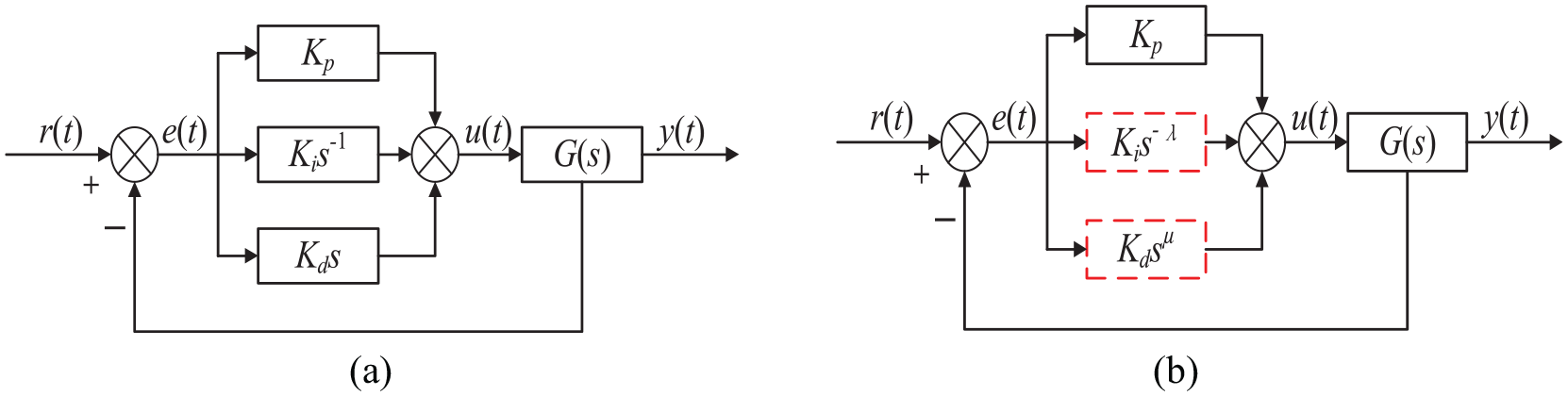
PID controller structure block diagram: (a) conventional PID control and (b) fractional order PID control.
Within this particular framework, the variable r(t) is utilized to symbolize the input of the system, while y(t) is employed to represent the output of the system, the system error signal is denoted as e(t), u(t) is utilized to the signal output of the FOPID, the transfer function of the regulated system is represented by G(s). Figure 3 depicts the parameter selection range for PID control and FOPID control when integral and derivative orders are regarded as coordinate axes. In the case of integer-order PID controllers, the parameters are constrained to a finite number of points within the coordinate system. On the other hand, FOPID controllers have the capability to flexibly modify their parameters within the specified interval of (0, 2) according to the specific requirements. Hence, FOPID controllers possess two supplementary adjustable parameters, thereby providing a heightened degree of flexibility and adaptability, which in turn has the potential to yield enhanced control performance.

Parameter selection of the controller: (a) PID and (b) FOPID.
Ride comfort and fluidity of motion are critical performance measures for suspension systems. Hence, the principal aim of this study is to mitigate the vertical oscillations of the semi-active suspension. 22 In order to achieve prompt damping, the FOPID control strategy for semi-active suspension is devised to regulate the controllable damping force, as depicted in Figure 4.

FOPID control for semi-active suspension.
When considering the vertical movement of the suspension system, a desired force for vibration suppression, denoted as U, is implemented to regulate the vertical vibration of the vehicle body. FOPID controller is formulated with the objective of regulating the vibration suppression force U, as shown in equation (10).

in the equation, the coefficients Kp, Ki, and Kd correspond to the proportional, integral, and derivative terms, respectively; Additionally, λ and µ represent the integral and derivative orders, respectively; Lastly, e(t) signifies the error between the current state of the vehicle body and the desired state. The five adjustable parameters of the fractional-order PID controller individually determine the controller’s characteristics. Appropriately chosen values can optimize control effectiveness. Increasing the proportional parameter KP enhances system response speed, the integral term Ki is utilized to eliminate steady-state error, the derivative term Kd reflects the degree of error variation, the value of λ is related to the system tuning speed, and the parameter µ influences the system response time.
The adjustable damper, functioning as a semi-active actuator, applies a damping force that aligns with the direction of the piston’s movement. The mathematical representation for this phenomenon can be expressed as:

in the equation, Fexp correspond to actual output damping force, F0 correspond to passive damping force.
The utilization of adjustable fractional-order calculus in the FOPID controllers expands the controlled range and enhances precision. However, this advancement also introduces the challenge of increased complexity in parameter tuning. In order to ascertain suitable control parameters for FOPID systems, this study employs the optimization properties of genetic algorithms to fine-tune those values. Taking into account the performance indicators of vehicle body acceleration, suspension dynamic travel, and tire dynamic load for the 1/4 car suspension, and normalizing each indicator, the fitness function for the genetic algorithm is defined as follows:

in the equation: RMS [·] denotes taking the root mean square value;
Road excitation model
Random road excitation
The road roughness function is the term used to describe the change in the height y of the road surface relative to a reference plane in the direction x of the road. Following this, a spectral analysis is performed in order to acquire the power spectrum of the road surface. 23 Commonly employed techniques for obtaining the time-domain model of a vehicle include the white noise approach, harmonic summation method, and PSD discrete sampling method. In this paper, the random road surface expression established using the white noise filtering method is as follows:

in the equation, zr represents the random road surface signal; fn represents the lower cutoff frequency, typically taken as 0.06–0.07 Hz; n0 is the spatial reference frequency; G0 represents the road roughness coefficient; v represents the vehicle speed, assuming the vehicle is moving at a constant speed; w(t) represents the white noise signal.
The simulation incorporates a driving speed of 20 m/s for the vehicle, while the road surface grade is classified as level C. C-class road surface roughness is represented by a geometric mean value of 256(10−6 m3). The road excitation acquired by simulation in Matlab is illustrated in Figure 5.
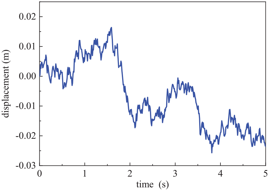
Simulation curve of random road input.
Convex hull road excitation
During the operation of the vehicle, it encounters road surfaces with irregularities such as speed bumps and depressions. The effects of these hits are distinguished by their brief durations and significant intensities, perhaps leading to discomfort or possibly posing a risk to the individuals inside the vehicle. Hence, it is imperative for the suspension system to possess the ability to efficiently attenuate the vibrations induced by these impact road surfaces. In order to evaluate the damping effectiveness of suspensions on impact road surfaces, this study establishes a model of an impact road surface to accurately recreate such situations. Its mathematical model is as follows:

in the equation, H is used to describe the peak height of the impact road surface, H = 0.06 m; W0 is used to describe the width of the impact road surface, W0 = 0.08 m; v is used to indicate the vehicle speed. The simulation yields the impact of road surface excitation, as depicted in Figure 6.

Simulation curve of impact road input.
Simulation and analysis
Random road simulation
In order to compare the control effects of different controllers on the system, this study additionally selects fuzzy PID control for comparison, the values of Kp, Ki, and Kd are determined using fuzzy logic. The input variables for fuzzy logic are determined by vehicle body acceleration and vertical velocity, respectively. 2 The parameter tuning results for PID are as follows: Kp = 223, Ki = 8459, and Kd = 336. The control parameters for Fuzzy-PID are based on the parameters of the PID controller. The parameter tuning results for Fractional PID are as follows: Kp = 571, Ki = 9445, Kd = 681, λ = 0.766, and µ = 0.481.
In order to ascertain the viability and efficacy of fractional-order theory in the realm of suspension control, the simulation study is performed using the pre-established random road surface and suspension model. Furthermore, the comparative study utilizes the simulation findings of both passive and typical PID-controlled suspensions.
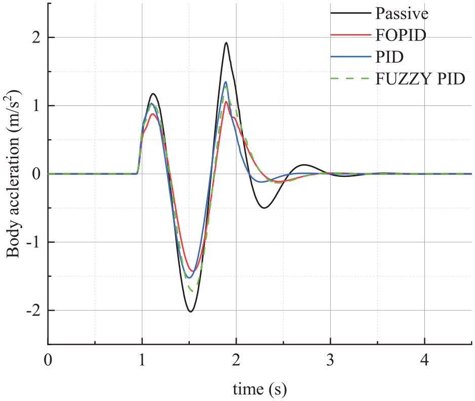
Figures 7 to 9 display the simulation results pertaining to the suspension’s pertinent performance statistics. The analysis of Figure 7 reveals that when subjected to random road surface excitation, both the FOPID-controlled, Fuzzy-PID-controlled, and traditional PID-controlled suspensions demonstrate significant reduction in vehicle body acceleration. This reduction in acceleration contributes to an enhanced level of comfort in comparison to passive suspension systems. Moreover, it has been observed that FOPID control exhibits enhanced damping characteristics and higher ride comfort in comparison to conventional PID control.
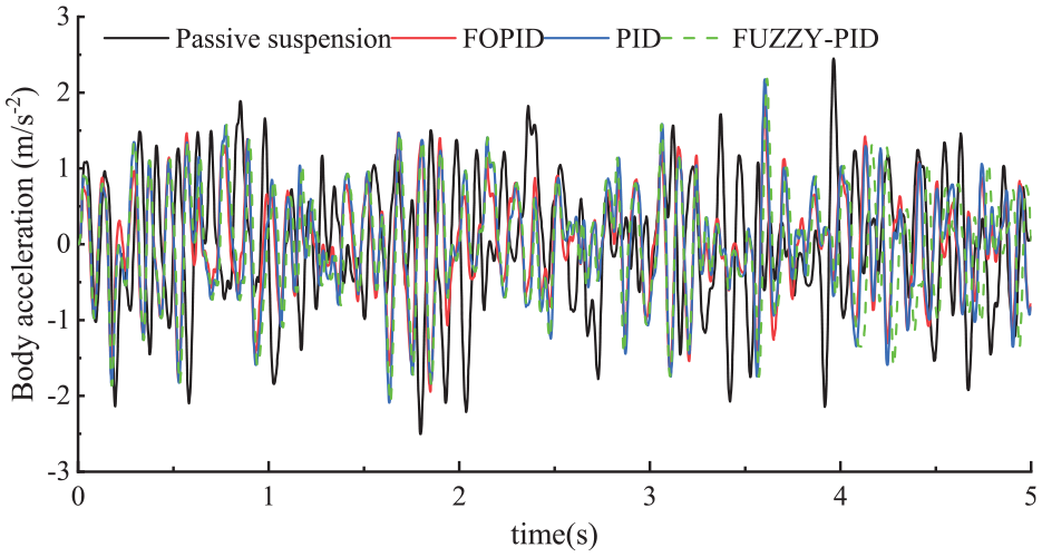
Body acceleration under random road.

Suspension deflection under random road.

Tire load under random road.
Figure 8 illustrates that both FOPID, Fuzzy-PID-controlled, and PID-controlled suspensions exhibit marginal enhancements in suspension dynamic travel. This implies that, based on the proposed control schemes, there is an improvement in driving smoothness. It is worth mentioning that the decrease in suspension deflection achieved with FOPID control exhibits a marginally smaller magnitude compared to that achieved through conventional PID control and Fuzzy-PID control. Moreover, in the high-frequency peak range, the performance of FOPID control is comparable to that of Fuzzy-PID control. Nevertheless, this compromise is deemed acceptable due to the enhanced levels of ride comfort and driving safety that are attained. Based on the findings shown in Figure 9, it is evident that the suspension system controlled by FOPID demonstrates a slight decrease in tire dynamic load in comparison to both PID control and passive suspension. This suggests that the suspension system controlled by FOPID algorithm, in addition to improving ride comfort, is capable of maintaining satisfactory traction, hence leading to an enhancement in driving safety.
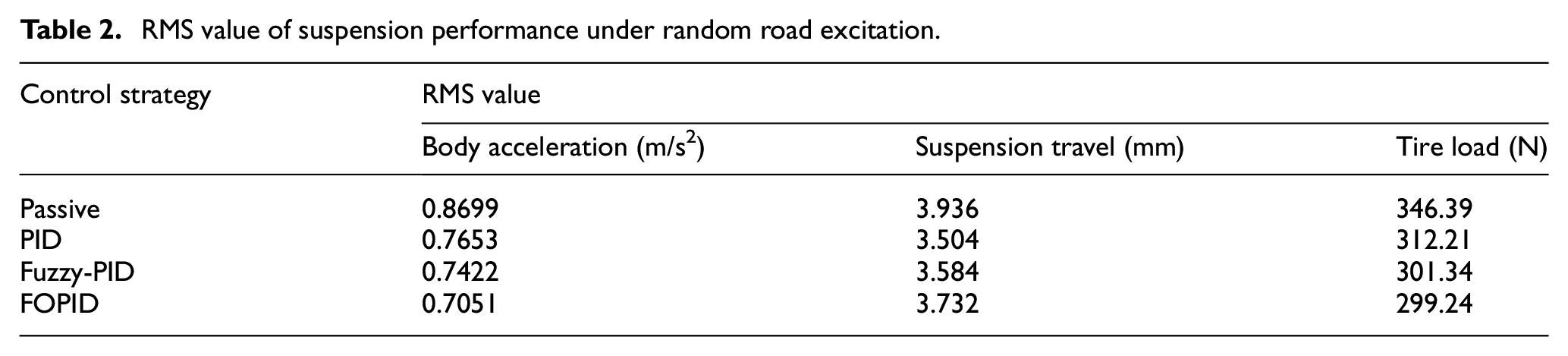
The root mean square (RMS) values of the suspension system’s simulation results are derived from the processing of its numerous performance indicators, as presented in Table 2. Figure 10 depicts the percentage decrease in the assessment metrics of the controlled suspension in relation to the passive suspension.
RMS value of suspension performance under random road excitation.
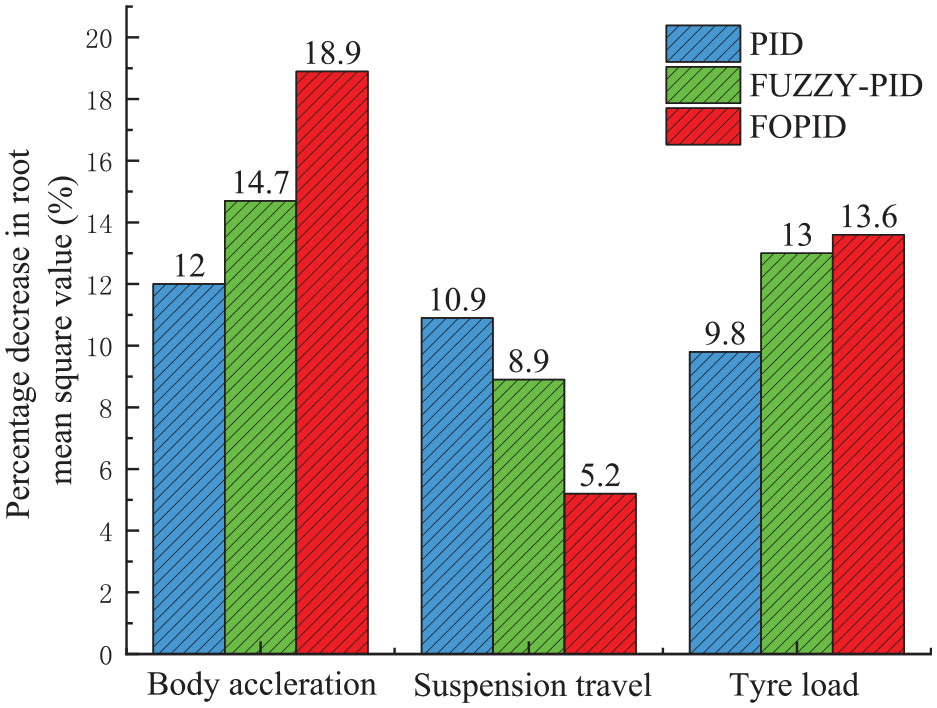
Comparison of control effect on random road.
The analysis of Table 2 reveals a clear indication that the implementation of FOPID control in the suspension system leads to a notable enhancement in performance when subjected to random road surface excitation, as compared to the passive suspension. The efficacy of the suggested FOPID control approach in the domain of semi-active suspension is substantiated, surpassing conventional PID control and Fuzzy-PID control in terms of performance. Figure 10 provides additional visual evidence that the suspension system controlled by the FOPID algorithm effectively diminishes vehicle body acceleration by 18.9% in comparison to the passive suspension system, Outperforming Fuzzy-PID control by 4.2%. On the other hand, the suspension system controlled by the PID algorithm reduces vehicle body acceleration by 12%. Compared with FOPID, PID control has better effect on reducing the dynamic travel of suspension. Compared to the passive suspension, the FOPID reduces the dynamic load of the tire by 13.6%, Outperforming Fuzzy-PID control by 0.6%, while the PID reduces by 9.8%.
Convex hull road simulation
In order to further enhance the credibility of FOPID control in suspension applications, this work conducts simulations to assess the damping effect experienced by a vehicle when it contacts road surfaces with impact. Simulation study is performed on both semi-active and passive suspensions in response to impact road surface stimulation. Figures 11 to 13 display the pertinent performance statistics for the suspension when subjected to impact from road surfaces.
Body acceleration under impact road.

Suspension deflection under impact road.

Tire load under impact road.
Based on the analysis of Figure 11, it is evident that the implementation of FOPID controlled suspension in impact road surface conditions leads to a substantial reduction in vehicle body acceleration. Notably, the peak values of vehicle body acceleration are considerably lower when compared to both the standard PID controlled suspension, Fuzzy-PID-controlled, and passive suspension systems. This finding suggests that the amplitude of vibrations sent to the vehicle chassis is effectively attenuated during instances where the vehicle traverses over speed bumps and other rough road surfaces, leading to a noticeable enhancement in the overall smoothness of the riding experience. The impact of road surfaces on suspension travel, as depicted in Figure 12, does not provide a substantial enhancement with FOPID control in comparison to PID control and Fuzzy-PID-control. However, this outcome falls within an acceptable range of suspension travel. Figure 13 demonstrates that the peak tire dynamic load achieved with FOPID control is comparatively lower than that attained by the PID controlled and Fuzzy-PID-control, and notably lower than the passive suspension when subjected to impact road surface stimulation. The aforementioned observation implies that the implementation of the FOPID control method contributes to the improvement of the safety measures of the suspension system in situations involving impact road surfaces.
Table 3 presents the maximum values of suspension performance metrics when subjected to impact road surface conditions. Meanwhile, Figure 14 visually represents the percentage decrease in peak performance metrics for each semi-active suspension in comparison to the passive suspension. Based on the data presented in Table 3 and Figure 14, it is evident that the suspension system controlled by FOPID exhibits a notable reduction of 29.4% in peak values of vehicle body acceleration when compared to the passive suspension system. Furthermore, the fuzzy PID control, compared to the passive suspension, exhibits a reduction of 25.2%, with control effectiveness on par with PID control. The FOPID-controlled suspension demonstrates considerable enhancement in tire dynamic load compared to PID control, resulting in significantly reduced values when compared to the passive suspension. In terms of suspension travel, the performance of FOPID control is slightly inferior to traditional PID control. Both FOPID and Fuzzy-PID exhibit a less effective restriction on suspension travel compared to PID control. However, this does not imply that FOPID control does not contribute to the improvement of vehicle comfort and handling stability. In brief, the FOPID-controlled suspension system exhibits superior damping performance relative to passive and standard PID-controlled suspensions when the vehicle encounters impact road surfaces.
Peak suspension performance under convex hull road excitation.


Comparison of performance peaks under impact road.
Conclusion
The creation of a FOPID controller was accomplished by integrating fractional-order theory with classic PID control for the semi-active suspension system of the car, which utilizes the precision and adaptability of fractional-order systems. The implementation of configurable fractional-order calculus in this controller serves to broaden the controlled range and improve precision. A simulation investigation was conducted utilizing models for random road surface and speed bump-like road surface excitations. The results suggested that both FOPID control, Fuzzy-PID control, and standard PID control procedures were helpful in boosting suspension performance. Furthermore, FOPID control displayed superior control performance, supporting the efficiency of fractional-order theory in suspension system control.
The selection of settings for FOPID controller has the potential to result in oscillatory behavior or even system instability. Therefore, genetic algorithms were utilized for tuning PID parameters. In this work, the initial FOPID parameters were established by considering the inherent properties of the system and drawing upon empirical knowledge. Following this, a genetic algorithm was employed for the purpose of optimization. It is imperative to acknowledge that during the process of determining controller parameters, further consideration must be given to factors such as disturbance suppression and response speed in order to obtain a comprehensive controller design.
Footnotes
Handling Editor: Chenhui Liang
Declaration of conflicting interests
The author(s) declared no potential conflicts of interest with respect to the research, authorship, and/or publication of this article.
Funding
The author(s) disclosed receipt of the following financial support for the research, authorship, and/or publication of this article: This research was financially supported by the the National Natural Science Foundation of China (No. 52165004), Key R&D project of Jiangxi Province of China (No. 20212BBE51009), Natural Science Foundation of Jiangxi Province of China (No. 20232BAB204041), Jiangxi Graduate Student Innovation Special Fund Project (No. YC2023-S463), Jiangxi Provincial Natural Science Foundation (20224BAB214081), and Double Height Project of Jiangxi Province Human Resources and Social Security Department.