
Abstract
Marine sediments are important for research in scientific fields such as marine geology, environmental testing of waters, marine biology and seabed resource exploration. Among them, mud miner is an important way to obtain sediments. However, due to the complexity of the marine environment, the seabed sampling operation is a relatively difficult and complicated project. The structural design of the sampler, the operation mode, and the interaction between the sampler and the sediment affect the sampling effect, which leads to the low efficiency of the sampler operation. In order to investigate the main factors affecting the drag force of the sampler during seafloor sampling, this paper takes a simple and portable anchor-type mud collector surface sediment sampler as a study. This paper introduces the mechanical structure and working principle of an anchor-type mud collector, establishes a mechanical model of the mud collector seafloor sampling process and derives the main factors affecting the dragging force: internal friction angle; the horizontal angle of the bi-directional shaft rod; undercut angle
Introduction
Marine substrate samples are widely used in marine geology, marine biology, soil science, seabed engineering and other research,1–3 as well as in the detection, assessment and investigation of the marine ecological environment in waters. 4 They are also important for the study of marine sedimentary processes, tectonic evolution and exploration of seabed mineral resources and other scientific fields. 5 The study of the geomechanical properties of submarine sediments, geological environment, water quality environment, soil chemical elements, etc., has profound research significance for submarine oil exploration and the laying of submarine cables.6,7 The study of substrate sample collection tools and collection methods has been of great interest to marine workers. Therefore, the research and design of efficient, scientific and novel marine sediment mud collectors are of great scientific value for waterside and marine research.
Experts and scholars at home and abroad have successively researched on mud collectors with various functions and structures in different regional application scenarios such as lakes, riverbeds and oceans. Bilici and Stark 8 studied a new sediment sampler with a cylindrical sampler in the structure, which used a free-fall gravimeter for geotechnical seabed profiling and sediment sampling, but due to the mechanical constraints it was less effective for rocky clays. Mackie and Bailey 9 introduced an inexpensive river sampler called T-type sampler. With a closed structure design, the sampler can be used in deep water and operated flexibly to accurately measure the depth of sediment penetration according to the user’s needs and collect sediments more effectively, but the T-type sampler cannot be used to sample sediments under rocks larger than 11.5 cm long, and its scope of application is low. Serge Heussner 10 scholars designed a multifunctional sediment collector by combining mooring and control technolo-gies with a mud harvester structure, with a collection area of 0.125 m2, which can collect and seal six samples of settled particles continuously in water depths up to 3,500 meters water depth, but with lower trapping efficiency and higher data bias in complex operating environments. Beattie 11 structurally improved the reliability of the device by strengthening the upper bracket to transmit the downward thrust and improved the release mechanism to increase the efficiency of the device. Improvements to the Ekman-Birge heavy-duty benthic sampler have led to the design of a new sampler for sampling peat substrates in Lake Friesland, but the shallow depths sampled can only be applied to specific operational scenarios. Hong and Roger 12 developed a portable manual collector for shallow water surface sediments based on a lever system. The structure is composed of a PVC pipe and a 1-m long support rod, the sediment collector has the advantages of easy operation, easy portability and manual. It is suitable for use in clear waters such as cold-water lakes, but is not suitable for use with complex, turbid operating sites. McLaughlin et al. 13 developed a new concept of remotely controlled column sampler using wireless electronic remote control and sonar technology, which is capable of collecting lake water samples simultaneously at multiple depths at the same location, from near the surface to the sludge layer, without the need to redeploy the samples and manned boat at the same location in the lake, but the sampler cannot be used to collect samples deeper into the sludge layer. Cheng et al. 14 studied a new type of box-type mud collector that can reduce the leakage of water from the bottom of the box, avoid the washing of sediment samples inside the box by water flow, and realise the collection of in situ samples of riverbed sediments. With the structural design of the gear shovel with sealing strip, water drain hole in the upper part of the box and elastic decoupling, it has the advantages of good sealing, strong adaptability, high success rate, etc. and ensures the in situ characteristics of the sediment samples. However, its large structural size leads to operation difficulties. Based on the above mentioned research of experts and scholars at home and abroad, this paper researches the anchor-type surface sediment harvester based on the working principle of boat anchor, creatively invented the mechanical linkage mechanical structure of the upper and lower covers, and realised the collection and preservation of the bottom sediment. Distinguished from the traditional grapple sediment collector, column gravity sediment collector, box sediment collector and other traditional sediment collector’s working method, it has the characteristics of lighter weight, simple structure and easy portability. It greatly reduces the working intensity of sampling personnel, improves the sampling efficiency, especially reduces the sampling conditions of surface sediments in the strong current sea area and has the value of application and promotion.
In order to better understand the motion mechanism and stress state of the seafloor sediment sampler based on the application practice of the mud picker, researchers have studied the seafloor sediment sampling process from different perspectives through numerical simulation of the operation process of the mud picker in lakes, riverbeds and oceans based on the design of the mechanical structure of the mud picker, aided by the rapid development of simulation software. Guo et al. 15 developed a new fidelity sampler for seafloor sediments, and studied and analysed its thermal insulation performance. Based on ANSYS software, a finite element model of the temperature of the sample cylinder was established. A hybrid finite element finite difference method was used for mathematical modelling to calculate the two insulation methods. Santner et al. 16 used numerical simulations of diffusion within the diffusion gradient of a thin film (DGT) sampler and found that the effect of lateral diffusion within the sampler on solute flux into the sampler is a non-linear function of diffusion layer thickness and physical sample size. Guo et al. 17 used ABAQUS software to study the soil–tube interaction during sampling using Euler–Lagrange coupling (CEL) and showed that at a penetration depth of 50 mm, the penetration resistance of the sampling tube was 599 N. The pressure-holding transfer process of the overburden water was simulated using the dynamic grid technique and FLUENT software, and the results showed that the pressure flux of the sample could be guaranteed to be no more than 0.03%. Gao et al. 18 used the finite element-smooth particle hydrodynamics (FEM-SPH) method to numerically simulate the sampling process. He et al. 19 used the volume of fluid (VOF) method to model soft viscous seafloor sediments as non-Newtonian Herschel–Bulkley viscoplastic fluids, established a numerical model for tubular sampling, and investigated the effects of the sampling tube diameter, drainage area rate, penetration velocity and the effects of sediment dynamic viscosity on coring rate and volume. The results showed that the coring volume was negatively correlated with all parameters except the sampling tube diameter.
The above-mentioned experts and researchers focused on the mechanical structure and application experiments of different mud collectors for different geographical applications and achieved very good results. In the numerical simulations mainly from the perspective of the dynamic process of mud collection by the mud collector, the force between the sampler and the mud, etc., were analysed, providing different research methods and experimental perspectives for future research on mud collectors. However, it is rare for studies to analyse the mechanical factors affecting the drag force of the mud collector in the process of seafloor sampling using a combination of numerical simulations and land-based experiments to simulate and verify the factors affecting the drag force of the mud collector. In this paper, a flexible, simple and portable anchor-type surface sediment picker (hereafter referred to as the picker) was used as the research object, in order to verify the scientific validity and practicality of the design of the mud collector, sea trial tests were conducted on the collector. And the locations of the seafloor sediment collection test sites were: collection point A (30°38′N, 123°32′E), collection point B (30°33′N, 123°34′E) and collection point C (30°29′N, 123°40), the sampling map locations and experimental test set up is shown in Figure 1. The paper introduces the mechanical structure and working principle of the mud collector, analyses the factors affecting the drag force by establishing a mechanical mathematical model of the sampling process of the mud collector on the seabed, and carries out numerical simulations using the SPH-FEM coupling method through ANSYN/LS-Dyna software to determine the main factors affecting the drag force Q. However, as there are too many factors affecting the complex marine environment, it is more difficult to control the variables; therefore, the experimental analysis to simulate the subsea environment was performed on land. According to the indoor experiments, the obtained experimental results were compared with the simulation results to verify the simulation validity of the SPH-FEM method and finally the main factors affecting the drag force Q were summarised and analysed. This study provides a new approach to the study of the forces on the mud collector, providing a theoretical approach to the sampling process and reducing the intensity and difficulty of manual work.

(a) Sampling map locations and (b) experimental test set up.
Mud picker structure and working principle
Structural components
The main body of the mud collector consists of a double weighting bar that rotated 180° in the vertical direction, a bi-directional shaft, an upper and a lower cover, four steel plates welded together to form an open collection device at the upper end – a ‘V’ groove – and a balancing bar, which is a symmetrical entity with the bi-directional shaft as its axis. The upper and lower covers are connected by a mechanical linkage rod, which supports the opening of the upper cover when the lower cover is subjected to a force; the two sides of the directional balancing rod are bolted so that the mud collector moves in the direction of the opening of the ‘V’ slot, preventing the sampling process from tilting or reversing from side to side. The specific physical and structural diagram is shown in Figure 2.

(a) Picture of anchor-type mud collector and (b) schematic diagram of anchor-type mud picker.
Working principle
The anchor-type surface sediment mud collector operates on a similar principle to that of a ship’s anchor. The mud collector is moved away from the vessel by the impact of the current and gravity, and during the contact of the bottom of the ‘V’ trough with the seabed by gravity, the bottom cover is pushed by the impact of the waves on the seabed to form a certain inclination with the seabed. When the lower cover is in contact with the seabed, the lower cover is squeezed by the seabed and the upper cover is opened by the mechanical linkage. Due to the bi-directional balance bar, the mud collector can only move in two directions and collects the mud into the ‘V’ groove under the action of the dragging force. When the lower cover is detached from the seabed, due to its own gravity, the lower cover is moved down and the upper cover is pulled down by the mechanical linkage, the upper cover is closed with the ‘V’ groove, locking the sediment inside the device. In practice, in weaker seas, the vessel can be driven for some distance after the mud collector has been thrown to obtain a greater impulse, so that the mud collector forms a greater angle with the seabed, creating a downward anchor grip during the towing process and dragging the sediment into the ‘V’ tank. A sketch of the mud collector’s operation is shown in Figure 3.

Mud collector working diagram.
Mud collector modelling analysis
Mechanical model of the mud collector
According to the geometrical characteristics and mechanical structure of the mud collector, the upper and lower covers of the ‘V’ slot were replaced by parallelograms and the bi-directional shaft was replaced by a rectangle, simplifying it to a two-dimensional model as shown in Figure 4. 20 The theoretical force analysis of the lower cover of the mud collector was applied based on the calculation method of the force on a flat anchor proposed by LeLievre and Tabatabaei, 21 Neubecker and Randolph, 22 and others. The soil wedge formed by the lower cover of the mud collector is in ultimate equilibrium with the force system. The soil pressure on the lower cover during the movement of the mud collector was analysed, and a theoretical mechanical calculation model of the drag force on the overall mud collector during the sampling process was established.

Simplified 2D model of the mud collector.
Due to the complex kinematics involved in the movement of the mud collector on the seabed, the lower cover of the mud collector is subjected to earth pressure from the soil in front of it during the process of mud extraction, and the soil is in a state of ultimate damage when the lower cover of the mud collector is continuously pushed. The contact between the mud collector and the seabed involves non-linearity, plastic and large deformations.
23
Assuming that the mud picker destroys the outer surface of the soil wedge during dredging, a top and side view of the mud change in front of the picker under the pull of the drag force is shown in Figure 5, with the mud on both sides extending to both sides at a shear angle Ψ. X is the width of the mud extending at the shear angle, B is the actual width of the picker, H is the maximum theoretical depth that can be dredged,

(a) Top view of the mud extraction process of the mud collector and (b) side view of the mud extraction process of the mud collector.
Force analysis of the mud collector
Force analysis of the lower cover wedge
During the mud picker, the interaction between the lower cover and the soil causes the soil to move in a wedge shape in the direction of the lower cover to produce slip displacement damage, which is caused by the lower cover and the balance bar of the mud picker. The trajectory of the soil body moves along the ABPD direction. The angle λ between the vertical direction and the soil movement is called the damage angle of the soil. At a certain depth of the mud picker operation, by studying the overall force balance condition between the lower cover and the soil, the interaction force
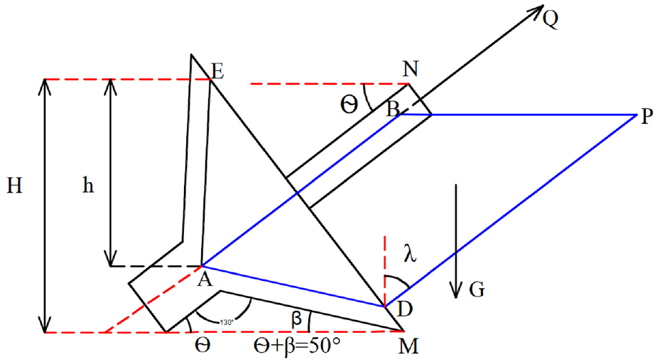
Diagram of the forces on the lower cover wedge.
Theoretical model calculation assumptions and descriptions:
(1) The drag force applied to the mud picker when picking mud is the drag force provided by the mud picker and the rope, and the direction of the drag force applied is along the direction of the bi-directional shaft bar.
(2) It is assumed that the damaged soil wedge is a rigid body and that the shear strength at the slip surface is fully effective.
The trajectory of the soil body along the ABPD direction presents a wedge-shaped movement. The soil body is subjected to extrusion with the lower cover of the mud picker force

(a) Schematic diagram of forces in contact with the seabed and (b) multilateral diagram of the forces.
The force

where
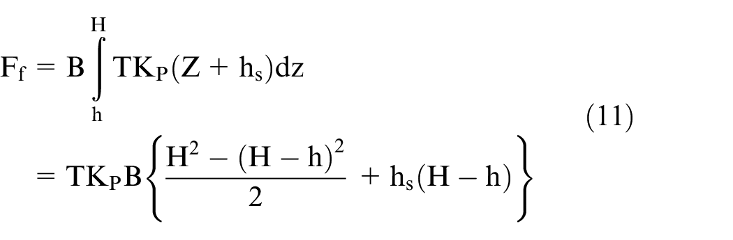
The force in contact with the seabed is shown in Figure 7. According to the force–multi-deformation geometry relationship, the lateral area

The width of the extension of the soil due to shear damage X is:

The weight G of the clay is derived from equations (3) to (4) as

where
From Neubecker and Randolph, 22 the existing theoretical lower cover is subjected to a frictional force F by the soil according to the following equation:
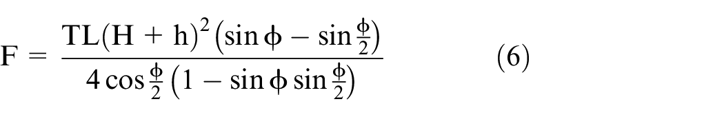
As the soil of the lower cover in the process of generating soil wedge damage with the force
Horizontal direction:

Vertical direction:

According to equations (7) and (8), it follows that,


where
The theoretical upper and lower lid forces are calculated assuming that the damage angle of the soil wedge in front of the lower lid is
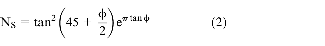
Based on the Cullen earth pressure theory, 26 the earth pressure of the clay in the initial phase was modified and calculated as follows:
where

Overall analysis of mud collectors
After the mud collector comes into contact with the seabed, it moves upwards to collect the soil into the ‘V’ trough, and the two-way shaft is subjected to a pulling force, and the seabed moves at a certain inclination angle

(a) Separated seabed force diagram and (b) multilateral diagram of seabed forces.
When the lower cover of the mud picker is detached from the soil, the bi-directional axial rod moves in a counter-clockwise direction relative to the soil, at which point the horizontal and vertical force equations for the device are:
Horizontal direction:

Vertical direction:

From equations (13) to (14), it follows that


The above analysis and calculation is in the ideal case, where the lower cover of the mud picker is in complete contact with the mud and the contacted mud is regarded as a rigid body; however, in the actual process of mud picking, due to the irregularity of the sea bed, especially in the sea sand and gravel, the mud picking effect is poor and some of the variables need to be adjusted. The mud picker forward front soil wedge is corrected by equations (11) and (12). When the mud picker is not in contact with the seabed, at which point h = 0 and H = 0, the lateral area A on both sides of the soil wedge and the width of shear damage extension X are both 0. Finally, a flow chart summarising the calculation of the theoretical force system of the mud picker is shown in Figure 9.

Flow chart of the theoretical force system of the mud collector.
The calculation steps for the drag force Q are as follows:
① According to the limit equilibrium condition of the soil wedge in front of the lower cover of the mud picker, for the mud picker at any position in space, first assume the damage angle λ of the soil, calculate the force
② According to the overall force conditions of the mud collector, the force balance equations in the horizontal and vertical directions are listed from the overall forces of the mud collector, and then
③ Vary the values in the range of the damage angle λ = 0°–90° and repeat steps ① and ② to find the minimum of all values of Q, that is, the drag force is optimal in this state.
This section established an overall mechanical model of the forces in the process of mud mining on the mud collector seabed, focusing on the overall force on the soil wedge during the sampling operation and the overall force analysis when the mud collector is separated from the seabed in the limit state. From the mechanical model, it can be concluded that the main factors in the force on the mud collector are the physical characteristics of the soil itself, the angle of internal friction
Materials and methods
Land-based mud mining test simulation
Experimental preparation
The experimental equipment mainly includes: the mud box carrier (2 m long, 0.8 m wide and 0.5 m high); a tension sensor and data collector; winch with a frequency converter and 100 mm diameter drum; simplified experimental mud picker and reversing switch, etc. Experimental set up: the winch is welded to the container at a distance of 2.3 m from the ground, the tension sensor is rolled at the same height and 0.4 m apart, the mud box carrier and the container distance is set to 0.35 m, the rope is connected to the winch which drives the mud picker, and the data collector outputs the rope tension via RS485 to the USB data line to the software of the host computer and records it. The overall dimensional adjustment diagram and the field experiment diagram are shown in Figure 10.
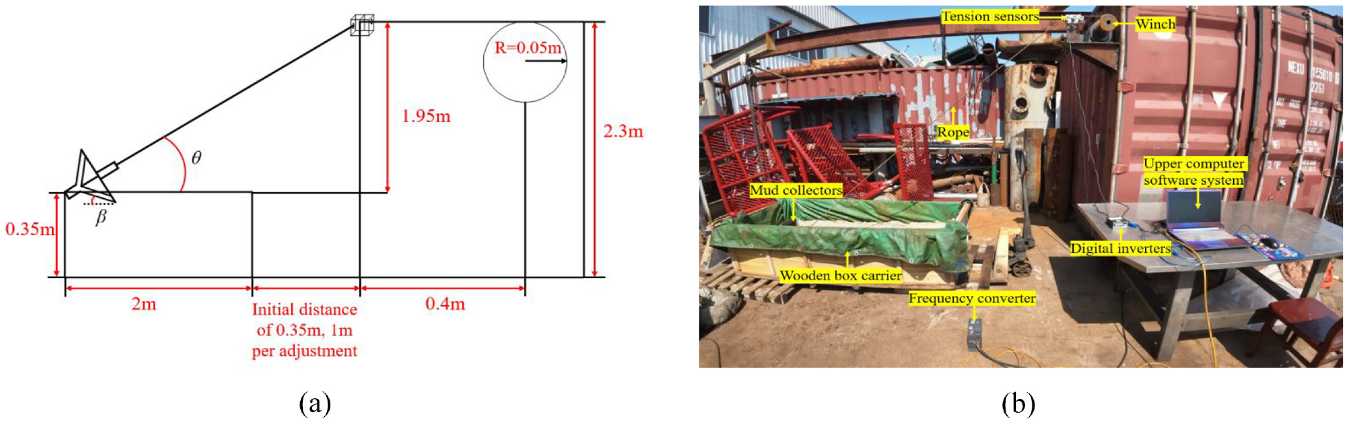
(a) Overall dimensions diagram and (b) diagram of field experiment set up.
Experimental results
Fine sand and clay were used as the experimental object. The speed of the winch was 0.2 m/s, the container and left end of the mud wooden box were maintained at 1.35 m, the horizontal inclination angle was set at 32.211° for the experimental parameters. In the winch dragging operation process, the lower cover before the soil wedge changed from a static state to breaking the limit equilibrium conditions; the mud picker cuts into the fine sand and clay due to the dragging force on both sides of the shear deformation. There was a large strain and large deformation phenomenon, and both sides of the fine sand and clay moved to pile up in the unconformed mud. The fine sand and clay field experiment process and drag force change diagram is shown in Figure 11.

Variation in drag force for (a, c) fine sand and (b, d) clay.
Numerical simulations
SPH method
SPH is a lattice-free particle method based on Lagrangian descriptions, originally developed for fluid mechanics problems.27,28 The basic idea of the method is to describe a continuous fluid (or solid) using interacting mass points, each carrying different physical quantities (mass, velocity, etc.), by solving the kinetic equations for the set of mass points and tracking the trajectory of each mass point, which leads to the construction of the SPH equations. This is often carried out in two key steps: first, obtain a kernel approximation in a continuous form as an integral representation, and the second step is called particle approximation.
In the SPH method, the concept of an integral representation of a function f(x) is defined by:

where
Based on the particle approximation, for a given particle i and its derivative are approximated by:

where
SPH-FEM coupled algorithm
Due to the complex coupling problems involving non-linearity, a high strain rate, large deformation and failure damage in the process of mud extraction, the mud collector in contact with the seabed requires numerical simulations that can reasonably simulate boundary distortion, crack expansion, coupled energy transfer and other problems, which inevitably places high demands on the grid accuracy requirements and computation time. For the Lagrange algorithm, the mesh distortion of large deformations can make the time step too small and lead to difficulties in calculation or even termination. The Arbitrary Lagrange–Euler (ALE) algorithm also has the problem of non-physical penetration of Euler material due to mesh incoherence. In order to overcome these various defects, the SPH method was used as it does not have the problems of mesh distortion and cell failure, and can easily track the trajectory of the matter and bury the intersection of different media at the interface, which is suitable for describing the large deformations of solid structures, the motion of fluid interfaces and the coupling of fluid–solid interactions. However, the SPH algorithm has the drawbacks of stretching instability, difficulty in imposing boundary conditions and, in particular, low computational efficiency. In view of this, the smooth particle hydrodynamic method (SPH) and the finite element method (FEM) were combined to establish a SPH-FEM-coupled sea bed model, where SPH particles transfer information such as stress and strain to the finite element mesh to ensure displacement coordination of the point–surface connection, using the SPH method to produce large deformations, shear damage and high strain regions with particle processing, and for smaller areas of deformation using FEM processing. The two parts of the seabed model are connected by point–surface contact coupling. The principle is shown in Figure 12.

Schematic diagram of SPH-FEM coupling.
Model building and meshing
The 3D drawing software SolidWorks was used to draw the ‘V’-shaped slot of the mud collector. The simplified model was imported into ANSYS/LS-Dyna for pre-processing to define the cell properties and material properties, and the mesh was divided by slicing, using a hexahedral mesh. The mesh size of the ‘V’ slot was 15 mm, and the simplified anchor type mud collector and mesh division is shown in Figure 13. The mesh size was 15 mm using the sweeping method of meshing to create a seabed model with a length of 2 m, a width of 0.8 m and a height of 0.5 m. The K-file formed after creating the mesh in ANSYN/LS-Dyna was imported into LS-Prepost for keyword modification. A coupled SPH-FEM 29 model of the seabed soil was created using LS-Prepost. Regions with large deformation and shear damage were created with SPH particles, and for deformed regions and regions with less shear damage were treated with FEM, both were connected by penalty functions. The SPH particle model was established to be 2 m long, 0.4 m wide and 0.25 mm high; a 1:1 scale was used to establish the overall SPH-FEM coupled model. The contact between the ‘V’ groove and the SPH particle is defined by the CONTACT_ERODING_NODES_TO_SURFACE keyword; FEM-SPH coupled soil model contact using point-surface automatic contact defined with the CONTACT_TIED_NODES_TO_SURFACE keyword, where the forces between the coupled models are transferred via penalty function constraints; the overall soil model imposes BOUNDARY_SPC_SET constraints to limit the degrees of freedom on both sides of the model and the bottom surface. Theoretically the study seabed is an infinite area; however, due to equipment limitations, part of the seabed was selected as the study object, using the keyword BOUNDARY_NON_ REFLECTING to set the soil without boundary conditions. The BOUNDARY_PRESCRIBED_MOTION_RIGID keyword is used to define only the degrees of freedom of the ‘V’ groove in the Y-axis and to limit the degrees of freedom of the other variables. The overall model uses the international unit system m–kg–s. The coupled SPH-FEM and overall finite element model of the seabed soil is shown in Figure 14.

(a) Simplified post-anchor mud picker and (b) mud picker meshing.

Coupled SPH-FEM model and overall finite element model of the seabed soil.
Material model construction
Mud collector
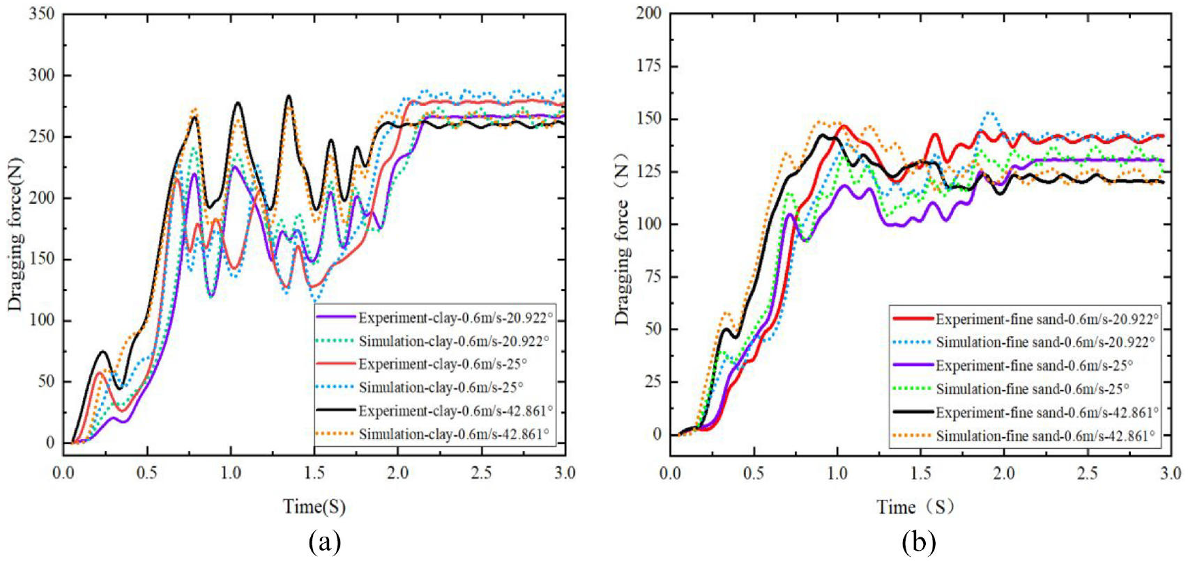
The mud collector is generally not deformed when moving on the seabed. The material of the mud collector is defined as MAT_RIGID rigid material with the specific material parameters listed in Table 1.
Mud collector materials.
Seabed soils
The LS-Dyna material library provides the soil model MAT_147 (MAT_FHWA_SOIL) material30,31 as a porous medium with a large number of complex parameters (including soil density, dry capacity, relative density of soil particles, cohesion, angle of internal friction, shear modulus, bulk modulus, water content, degree of porosity, etc.) as the object of study, which is based on the Mohr–Coulomb yield criterion 32 and a modified Drucke–Prager (D-P) plasticity model; the material adds parameters such as plastic hardening, stress softening and deformation rate, which can reflect the seabed soil properties relatively well and meet the requirements of simulation experiments. According to the paper,33–35 in fine sand models using the same geometry rock cover model MAT_025 (MAT_GEOLOGIC_CAP_MODEL), the model is a double viscous double invariant elastic plastic model, creating a better simulation of the overall plastic deformation of fine sand. The parameters of the seabed clay and fine sand models are as shown in Tables 2 and 3.
MAT_147 seabed clay material parameters.

RO: mass density; K: bulk modulus; G: shear modulus; MCONT: moisture content of soil; PHIMAX: peak shear strength angle; SPGRAV: specific gravity of soil used to get porosity; VN: viscoplasticity parameter; COH: Cohesion n shear strength at zero confinement; INTRMX: maximum number of plasticity iterations; AHYP: coefficient A for modified Drucker-Prager surface; ECCEN: eccentricity parameter for third invariant effects; EPSMAX: maximum principle failure strain.
MAT_025 seabed fine sand material parameters.

RO: mass density; BULK: initial bulk modulus, K; G: initial shear modulus; ALPHA: failure envelope parameter; THETA: failure envelope linear coefficient; GAMMA: failure envelope exponential coefficient; BETA: failure envelope exponent; R: cap, surface axis ratio; D: hardening law exponent; W: hardening law coefficient; X0: hardening law exponent; C: kinematic hardening coefficient; N: kinematic hardening parameter; PLOT: save the following variable for plotting in TAURUS; FTYPE: formulation flag; VEC: vectorisation flag; TOFF: tension cut off, TOFF < 0 (positive in compression).
Results and discussion
Comparison of SPH-FEM and experiments
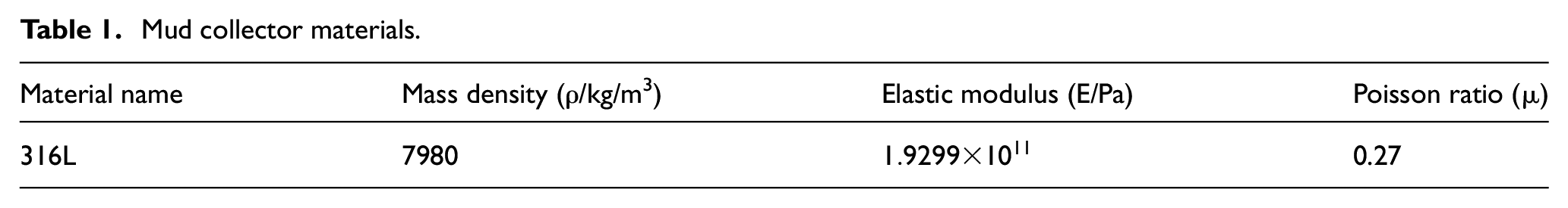
In order to verify the effectiveness of the SPH-FEM coupling method, the numerical simulation and field tests were carried out using the same velocity of 0.1 m/s and a horizontal inclination angle of 32.211°. The fine sand and clay tests were selected to verify the magnitude of the drag force, and the working processes of the fine sand and clay field tests and numerical simulation are shown in Figure 15. The numerical simulation and test results and error bar comparison for clay and fine sand are shown in Figures 16 and 17. The simulation versus test and error bar comparison plots show that the overall error values of the numerical simulations and field tests were acceptable. This indicates that the coupled SPH-FEM method simulating clay and fine sand collection by a mud collector is reasonable and acceptable for the numerical simulation.

(a) Fine sand test procedure, (b) clay test procedure and (c) numerical modelling procedure.

Clay simulation versus experimental results (a) and error bars (b).
Comparison graph of fine sand simulation versus experimental results (a) and error bar graph (b).
Factors affecting towing forces
Influence of soil type
Two soil types were used for the experiments: clay and fine sand (Figure 18). Using the controlled variable method, the distance between the left end of the soil carrier and the container was maintained at 3.1 m, that is, the angle of the horizontal inclination angle θ was guaranteed to be constant at 32.211°, resulting in an angle β of 17.789°. The speed of the winch was adjusted by means of a frequency converter to 0.1, 0.2, 0.4 and 0.6 m/s for the dragging experiments. The drag force simulation and experimental speed variation are shown in Figure 19.

(a) Fine sand and (b) clay.

Numerical simulation and test drag force variations for clay and fine sand at 0.1, 0.2, 0.4 and 0.6 m/s for (a), (b), (c) and (d), respectively.
Through the experimental and simulation data obtained throughout the overall mud mining process, the different clay and fine sand drag forces gradually increased with time. In Figure 19(a) to (d), the drag force of clay was greater than the drag force of fine sand; in 0–1 s, the drag force of clay was greater than the drag force of fine sand due to the lower cover of the mud collector cutting into the clay and fine sand producing shear deformation and large strains, with an internal friction angle of the clay of about 30.99° and 25.66° for fine sand. The other physical parameters of the two soil types were also different, and the internal friction angle was the key factor affecting the drag force.
Horizontal inclination
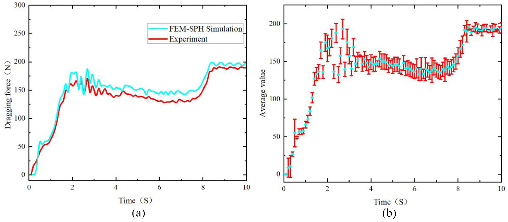
Experiments were carried out on the two types of soil while keeping the sensor and the winch in the same horizontal position, the inclination angle θ formed by the sensor and the mud carrier constant, and the speed of the winch constant at 0.6 m/s, while adjusting the distance between the left end of the container and the mud carrier at a distance of 2.1 m and inclination angle of 20.922°, 4.1 m and inclination angle of 25° or 6.1 m and inclination angle of 42.861°. The drag force curves for the mud collectors at different horizontal inclinations are shown in Figure 20.
(a) Variation in drag force at different inclination angles for clay and (b) variation in drag force at different inclination angles for fine sand.
Through the experimental and simulation data, it can be observed that, in the overall mud mining process, the lower cover of the mud collector cut into the clay and fine sand within 0–0.75 s. From Figure 20(a) and (b), it can be concluded that as the horizontal inclination angle of the cut θ increased from 20.922° to 42.816°, the portion of the collector shovelled into the soil gradually increased and the drag force gradually increased. At 0.75–2 s, the full contact between the mud collector and the soil generated shear deformation. After 2 s, as the mud collector was in full contact with the soil, the soil in the ‘V’ groove of the mud collector reached saturation and the drag force varied within the dynamic range of the equilibrium state. Throughout the whole mud mining process, the dragging force had the greatest influence at the beginning; then, with the increase in the horizontal inclination angle θ and the decrease in the undercut angle β, the dragging force gradually increased and finally trended towards dynamic equilibrium.
Winch speed
Clay and fine sand were used as two different media, the distance between the clay carrier and the left end of the container was set to 3.1 m, the angle of horizontal inclination θ was held constant at 32.211° and the winch speed was adjusted to 0.2, 0.4, or 0.6 m/s. The changes in dragging force are shown in Figure 21.

(a) Graph of drag force variation at different winch speeds for clay and (b) graph of drag force variation at different winch speeds for fine sand.
Through the experimental and simulation data obtained throughout the mud mining process (Figure 21(a) and (b)), in both the clay and fine sand with different speeds, the mud collector cut into the clay and fine sand with irregular movements from 0 to 2 s. In 2–5 s, the mass of clay and fine sand collected by the mud miner increases gradually with increasing speed, and finally reached the saturation state. In the actual operation, the drag force gradually increased with increasing speed in the same time, the mass of clay and fine sand collected gradually increased, which in turn led to a gradual increase in the dragging force of the mud collector.
Conclusions
This paper introduced the mechanical structure composition and operating principle of a mud collector, established a mechanical model of the bottom sampling process of the mud collector, and designed and investigated experiments using the mud collector in different soil environments to determine the parameters affecting the drag force Q during the operation of the mud collector. The collection process was simulated based on the coupled SPH-FEM method and the main influencing parameters were determined by comparing the experimental and simulation data. The full conclusions are as follows:
(1) The anchor-type surface sediment collector utilises the working principle of a ship’s anchor for its operation. Its composition is innovative: a mechanical linkage is welded together with a rotating shaft at the centre of the upper and lower cover; when the lower cover is in contact with the seabed, that is, the lower cover fits into the ‘V’ groove, the mechanical linkage will hold up the upper cover, and when the lower cover is detached from the seabed surface, the lower cover will move away from the ‘V’ slot under gravity, driving the mechanical linkage downwards, pushing the upper cover downwards to close the opening of the ‘V’ slot, so that the mud sample will not be washed away by seawater and will remain in the ‘V’ slot. The ‘V’ trough is closed by a downward movement of the connecting rod.
(2) A towing process was developed. The drag force Q was analysed to be mainly related to the horizontal angle θ of the bi-directional shaft, the effect of the undercut angle β, the soil itself and the actual drag speed in operation. It provides a theoretical basis for studying the movement of the mud collector on the seabed and reduces the labour intensity for the personnel operating the equipment.
(3) The SPH-FEM coupling method was used to effectively simulate the process of the mud collector cutting into and dragging the soil using LS-Dyna software. The SPH-FEM method effectively simulated the large deformation of the soil during operation, and the large deformation and dispersion on both sides had the effect of particle accumulation and splash with less actual error. The SPH-FEM method also effectively simulated the process of the mud collector cutting into the soil and dragging, and provides a more detailed view of soil changes and a more efficient calculation method.
(4) The main factors affecting the drag force of the mud collector were effectively verified by comparing experimental data and numerical simulation results. Different soil media affected the drag force of the mud collector; the horizontal inclination angle θ of the lower cover from 20.922° to 42.816° had the greatest influence on the drag of the whole mud collector process at the beginning stage; with the increase in the horizontal inclination angle and the decrease in the inclination angle of the bi-directional shaft rod, the dragging speed varied from 0.2 to 0.6 m/s, and the mass of clay and fine sand collected by the dredge gradually increased within 0–3 s, which in turn led to a gradual increase in the dragging force of the dredge.
As this paper was based on land experiments to simulate the seafloor operational state, but the seafloor topography and environmental coupling were complex, the theoretical modelling of the sampling process of the mud collector and the land experiments were carried out in a more ideal state. In future work we will suggest a more systematic focus on the seawater resistance and the influence of the mud miner structure on the dragging force. Considering the application scenarios of the dredge, simulations and experiments should be carried out in many different types of soils in subsequent work to obtain more systematic, accurate and scientific conclusions.
Research Data
sj-xlsx-1-ade-10.1177_16878132241241428 – Supplemental material for Numerical simulation and experimental study on seafloor sampling of an anchor-type mud collector based on SPH-FEM coupling method
Supplemental material, sj-xlsx-1-ade-10.1177_16878132241241428 for Numerical simulation and experimental study on seafloor sampling of an anchor-type mud collector based on SPH-FEM coupling method by Jiaqi Zhang, Bin Xue, Jun Liang, Yuanming Guo, Tiejun Li, Detang Li, Yonghe Xie, Jun Wang and Yongqiang Hong in Advances in Mechanical Engineering
Footnotes
Handling Editor: Chenhui Liang
Declaration of conflicting interests
The author(s) declared no potential conflicts of interest with respect to the research, authorship and/or publication of this article.
Funding
The author(s) disclosed receipt of the following financial support for the research, authorship and/or publication of this article: This research is funded by the National Key R&D Program of China (2019YFD0901205) and the Zhejiang Province ‘Pointer’ and ‘Leader Goose’ R&D Program of Zhejiang (2022C03023).
References
Supplementary Material
Please find the following supplemental material available below.
For Open Access articles published under a Creative Commons License, all supplemental material carries the same license as the article it is associated with.
For non-Open Access articles published, all supplemental material carries a non-exclusive license, and permission requests for re-use of supplemental material or any part of supplemental material shall be sent directly to the copyright owner as specified in the copyright notice associated with the article.