
Abstract
Time-varying meshing stiffness is one of the important excitations of gear transmission system, and its accurate calculation is an important basis for gear dynamics research. This paper proposes an improved potential energy method to calculate the theoretical time-varying meshing stiffness of healthy gears and helical gears with root crack faults, taking into account the non coincidence between the tooth root circle and the base circle of the helical gear, as well as the angle of the tooth root transition circle, the simulation results of KISSsoft were used to verify the rationality and effectiveness of the improved method; analyzed the influence of basic parameters and fault severity of helical gears on time-varying meshing stiffness. The results show that the accuracy of meshing stiffness obtained by the improved method has increased by about 5%; changes in the basic gear parameters cause changes in the contact ratio, which in turn leads to changes in the fluctuation and average value of the gear meshing stiffness; the fluctuation of meshing stiffness is in the minimum value when overlap contact ratio is close to an integer, the fluctuation of meshing stiffness is in the maximum value when total overlap is near an integer; the variation of crack depth and angle leads to local attenuation of time-varying meshing stiffness of helical gears. As the degree of failure increases, the local attenuation of meshing stiffness becomes more pronounce and compared to crack angle, meshing stiffness is more sensitive to changes in crack depth. Compared with the traditional potential energy method, the improved method improves the calculation accuracy of the time-varying meshing stiffness of helical gears, which is highly practical in the accurate calculation of helical gear meshing stiffness excitation and provide the theoretical basis for the calculation of the meshing stiffness of helical gears.
Keywords
Introduction
Gear transmission system is widely used in vehicles, aerospace, ships, and other fields, 1 which has the advantages of small size, high transmission efficiency, and large transmission ratio. With the continuous improvement of mechanical system performance requirements, gear systems are developing toward high speed, heavy load, and low noise, which makes them work in extreme environments for a long time, leading to faults such as cracks, pitting, and wear on the teeth of gears,2,3 the failure of gear teeth not only affects the normal operation of the gear transmission system, but also causes damage to the entire machinery. As one of the important excitations, the time-varying nature of the gear meshing stiffness has a great influence on the vibration characteristics of the gear system, and in the gear transmission system, the coupling between torsional and transverse vibration is mainly caused by the meshing stiffness. 4 The occurrence of gear faults can cause changes in meshing stiffness, thereby altering the dynamic behavior and vibration characteristics of the system.5,6 Therefore, accurately calculating the time-varying mesh stiffness is an important foundation for dynamic analysis of gear transmission systems and is also a research hotspot in the field of gear dynamics. 7
At present, there are mainly four methods for calculating the time-varying mesh stiffness of gears 8 : analytical method, finite element method,9,10 analytical-finite element method,11,12 and experimental method.13–15 Although the finite element method has higher accuracy, it is complex in computation and requires a large amount of computing resources and time. Although the experimental method provides real meshing stiffness, the experimental process is more cumbersome and the experimental cost is high. However, the analytical method has become a commonly used method due to its advantages of high solving efficiency and high accuracy. The analytical method also includes empirical formula method, material mechanics method, potential energy method, and so on. Among them, the empirical formula method can only solve the average meshing stiffness, while the material mechanics method can only solve the time-varying meshing stiffness of spur gears and the influencing factors such as tooth profile and gear tooth failure can be taken into account in the solving process. Therefore, when solving the time-varying mesh stiffness of helical gears, the potential energy method has become the most commonly used analytical method, and during the solving process, factors such as tooth shape and gear tooth failure can also be considered.
In recent years, scholars have conducted in-depth research on the calculation of time-varying mesh stiffness of spur gears. Yang and Lin 16 first proposed using the potential energy method to calculate the gear meshing stiffness, and regarded the teeth of spur gears as a variable cross-section cantilever beam, whose elastic deformation energy includes Hertz contact energy, bending deformation energy, and axial compression energy. On the basis of Yang’s work, Tian 17 considered the shear deformation energy of gears and calculates the time-varying meshing stiffness of the gear. Liang et al. 18 used the potential energy method to calculate the meshing stiffness of planetary spur gear pairs with cracks; Wu et al. 19 developed the method by introducing linear cracks in a spur gear pair model. Doğan et al. 20 studied the effects of different gear design parameters on meshing stiffness and contact ratio, and proposed different methods for calculating time-varying meshing stiffness. Kalay et al. 21 developed a numerical method to detect root crack damages in symmetric and asymmetric involute spur gears, to achieve this end, the single tooth stiffness values were calculated for healthy and cracked gears, and then the time-varying mesh stiffness was obtained. Liu et al. 22 considering the computational efficiency and accuracy of the meshing characteristics of gear pairs with root crack faults, established a parameter model for cracked spur gears by simplifying the crack propagation path. Many scholars have also conducted extensive research on the calculation of time-varying mesh stiffness for healthy helical gears and helical gears with root crack faults. Wan et al. 4 proposed a calculation method based on the cumulative integral potential energy method to solve the time-varying meshing stiffness of cracked helical gears by introducing a variable crack length model, and studied the influence of different helical gear parameters on the meshing stiffness. Pandya and Parey23,24 calculated the time-varying meshing stiffness of cracked spur gears and studied the effect of crack propagation paths on the time-varying meshing stiffness of gears under different gear parameters. In all the above literature, it is assumed that the cantilever beam starts from the base circle of the gear. However, when the root circle is larger than the radius of the base circle, the deformation between the root circle and the base circle are neglected. Therefore, some scholars have proposed improved formulas for calculating the time-varying meshing stiffness of gears. Ma et al. 25 proposed an improved gear cantilever beam model that takes into account the non coincidence of the root circle and base circle, and calculates the time-varying meshing stiffness of spur gears with root crack faults. In contrast to spur gears, helical gears generate axial forces that cannot be overlooked during the calculation of meshing stiffness, based on this, Wang et al. 26 proposed an improved method for calculating healthy helical gears and three cases are applied to validate the developed model. Then, Wang et al.27,28 proposed an improved calculation model for the meshing stiffness of helical gear systems caused by gear cracks, taking into account the lateral and axial stiffness of the gear foundation, and verified it with finite element simulation results. Yan et al. 29 proposed a new analytical model of meshing stiffness of helical gears using a combination of contact line analysis with slice method, which can well predict the dimensionless time-varying meshing stiffness. Yang et al. 30 improved the calculation of helical gear stiffness by considering flexible deflection and clearance. Huangfu et al.31,32 proposed a new method for calculating the time-varying meshing stiffness of helical gears with root crack faults by utilizing the slice method and the idea of “offset and superposition.” Hu et al. 33 constructed a time-varying meshing stiffness calculation methods for helical gear pairs in electric continuously variable transmissions based on the slice theory and numerical calculation methods, and the TVMS of the helical gear were calculated under different constant and time-varying torque in this study.
It is not difficult to find that most of the current literature focuses on using the potential energy method to calculate the time-varying mesh stiffness of healthy spur gears and helical gears, while there is relatively little research on the calculation method of time-varying mesh stiffness of helical gears with root crack faults, and the improvement of its method is not comprehensive enough. Based on the above issues, this article improves the traditional energy method in literature 4 by considering the non coincidence between the tooth root circle and the base circle of the helical gear, as well as the angle of the tooth root transition circle. The meshing stiffness of healthy helical gears and helical gears with root crack faults were calculated in three cases (the base circle of the driving gear and the driven gear were both larger than the root circle; the base circle was smaller than the root circle; the base circle of the driving gear was larger than the root circle, and the base circle of the driven gear was smaller than the root circle), and simulation was conducted based on MATLAB, and the correctness of the theoretical formula was verified using the simulation results of KISSsoft. Analyzed the influence of basic parameters of healthy helical gears and the degree of failure of faulty helical gears on time-varying mesh stiffness.
Improved calculation of time-varying meshing stiffness of healthy helical gears
Calculation of helical gear mesh stiffness by potential energy method
In this paper, the potential energy method
8
is used to calculate the time-varying meshing stiffness of helical gears. For spur gears, each tooth can be regarded as a variable cross-section cantilever beam, which undergoes deformation under the action of tooth surface load, and the model of a spur gear variable cross-section cantilever beam is shown in Figure 1. The time-varying meshing stiffness of gears consists of five parts: Hertz contact stiffness


Spur gear cantilever beam model.
The parameters in the above equations can be expressed in equations (6)–(12):


where,
In equation (5),

where,
Based on the above formula, the total meshing stiffness of the gear pair can be obtained, as shown in equation (16). The subscripts “1” and “2” denote the driving and driven gears respectively.

Due to the helical angle of the helical gear, the slicing method was used in literature 4 to cut it into multiple slices along the tooth width direction. By calculating the meshing stiffness of each slice and the cumulative integration along the tooth width direction, the meshing stiffness of the helical gear can be obtained.
Based on the method described in literature 4 and programmed using MATLAB, the results of calculating the single tooth meshing stiffness and total meshing stiffness of the helical gear under the basic gear parameter data in Table 1 are shown in Figure 2(a). Based on the KISSsoft gear specific analysis software, the parameters in Table 1 were introduced for contact analysis of helical gears. The comparison of the results of the two methods is shown in Figure 2(b).
Gear parameters.


Potential energy method for solving time-varying meshing stiffness of helical gears and comparative validation: (a) meshing stiffness of helical gear and (b) comparison of meshing stiffness.
After calculation, the helical gear transverse contact ratio and overlap contact ratio are (
Comparison of gear time-varying meshing stiffness data.

According to the comparison of the data in Table 2, it can be seen that the errors of the minimum, maximum, and average values of the total meshing stiffness obtained by the method in literature 4 are all above 10%. Although the trend of its calculation results is consistent, the lack of consideration for the non coincidence between the root and base circles of helical gears results in lower accuracy in calculating meshing stiffness. Therefore, this article proposes an improved potential energy method based on literature 4 to improve the accuracy of solving time-varying mesh stiffness.
Improved calculation method for healthy meshing stiffness
From the previous analysis, it can be seen that simplifying the calculation of the tooth on the base circle to a cantilever beam model is not accurate enough, because the tooth starts from the tooth root circle. When the gear base circle and tooth root circle do not overlap, the calculation of meshing stiffness will produce significant errors. Therefore, it is necessary to improve the traditional potential energy method. The improvement process is as follows.
The radius of the base circle is larger than the radius of the root circle
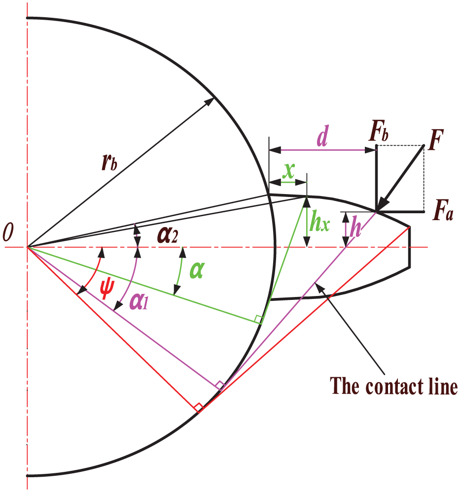
When the base circle radius is greater than the root circle radius, the traditional potential energy method calculates the meshing stiffness by simplifying the gear teeth as a cantilever beam on the base circle, which reduces the length of the cantilever beam and does not consider the deformation of the gear tooth transition between the base circle and the root circle, resulting in a large value of meshing stiffness. The three-dimensional and two-dimensional models of the improved variable-section cantilever beam of the gear tooth are shown in Figure 3.

Sliced model of helical gear cantilever beam for
According to the improved model shown in Figure 3, combined with the basic formula in literature, 4 the bending potential energy of each tooth after improvement can be obtained:

where,
The bending stiffness
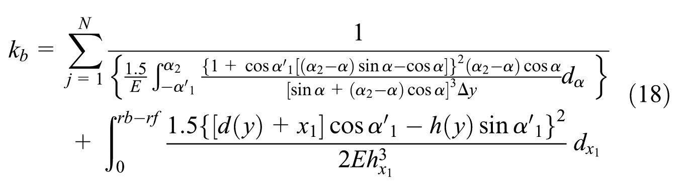
In equation (18),

In equation (19),

where,


According to the single tooth contact line length expression form can be discussed in two cases, and its detailed solution is as follows:
(1) Transverse contact ratio greater than overlap contact ratio (
The driving wheel

where,
The driven wheel

where,
(2) Overlap contact ratio is greater than transverse contact ratio (
The driving wheel

The driven wheel

Similar to the process of solving the bending stiffness


Radius of the base circle is smaller than the radius of the root circle
When the base circle radius is smaller than the root circle radius, the traditional potential energy method simplifies the gear teeth as a cantilever beam on the base circle, increasing the length of the cantilever beam and calculating the deformation of the teeth between the base circle and the root circle, which will result in smaller meshing stiffness calculations. Therefore, it is necessary to modify the upper limit of integration on the basis of the original meshing stiffness formula. The revised 2D model of the gear tooth cantilever beam is shown in Figure 4.

Sliced model of helical gear cantilever beam for
The bending stiffness


where,
Validation of the improved potential energy method
Based on MATLAB, the formula of the improved potential energy method was edited to calculate the time-varying meshing stiffness of helical gears, and compared and analyzed with the simulation results based on KISSsoft and the calculation results in literature.
4
For the case where the base circle and root circle of the gear do not coincide, three groups of gears with different sizes are taken for analysis. The first groups of gear parameters is selected as:

Comparison of time-varying meshing stiffness of three sets of gears: (a)
Three groups of gear meshing stiffness index data.
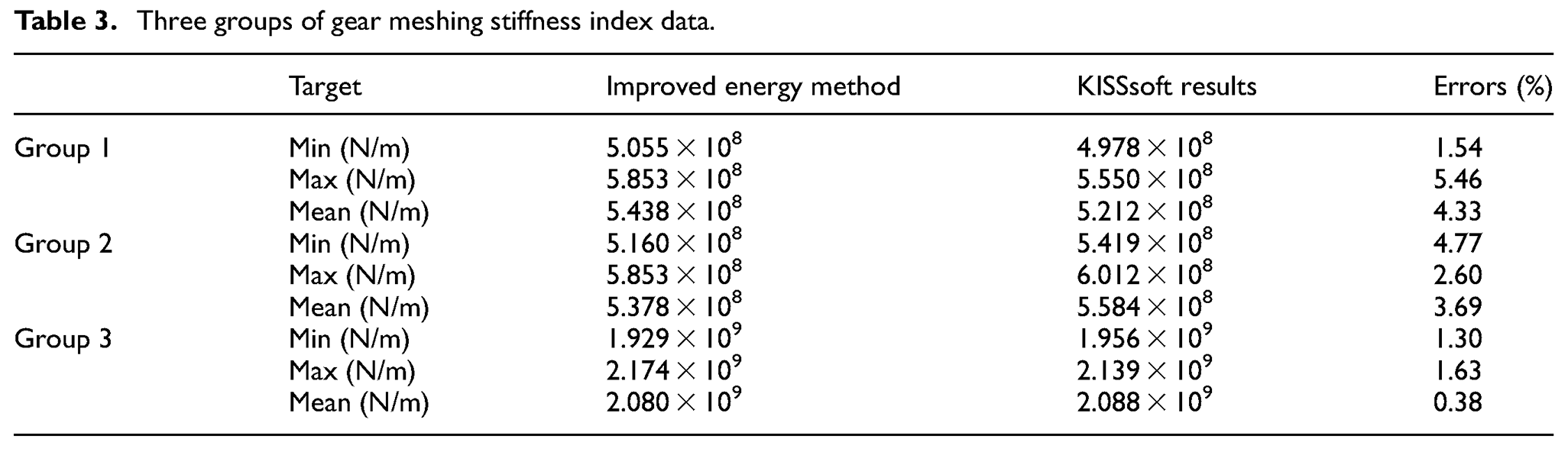
From the data in Figure 5 and Table 3, it can be seen that the error of the time-varying meshing stiffness of the helical gear calculated based on the improved potential energy method has significantly decreased, and the error of the three indicators is basically less than 5%, indicating a significant improvement effect. However, due to the influence of factors such as axial force and tooth surface friction of helical gears, the improved meshing stiffness results also have a small deviation from the simulation results of KISSsoft. By comparing the calculation results of literature, 4 the accuracy of time-varying mesh stiffness of helical gears calculated by the improved potential energy method is improved by about 5%–10%, which is more in line with the actual mesh stiffness of helical gears. By comparing the simulation results of KISSsoft, it is proved that the improved formula and theory are reasonable and in line with the actual situation.
Analysis of parameters affecting the meshing stiffness of healthy helical gears
Based on the improved potential energy method, this section will explore the influence of basic parameters of helical gears on time-varying mesh stiffness by changing the size of basic parameters (such as tooth width, helix angle, pressure angle, etc.) while ensuring that other parameters of helical gears remain unchanged.
Effect of helix angle on the time-varying meshing stiffness of helical gears
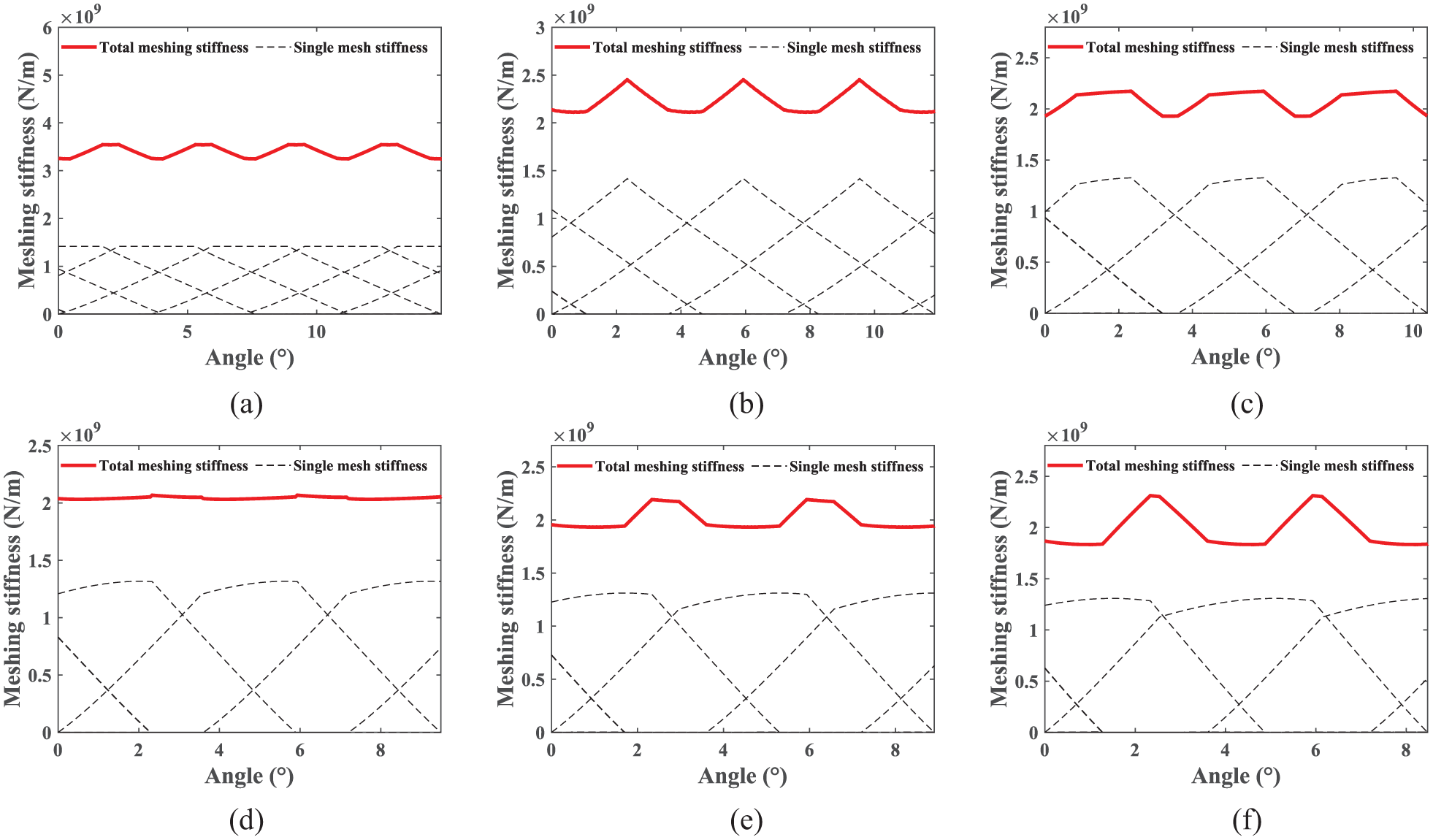
Based on the basic parameters of gears in Table 1, calculate the time-varying meshing stiffness of helical gears with helix angles of 3°, 6°, 9°, 12°, 15°, and 18°, as shown in Figure 6(a) to (f). The comparison of single tooth meshing stiffness at different helix angles and the comparison of total meshing stiffness are shown in Figure 7(a) and (b). The average and fluctuation values of time-varying mesh stiffness are shown in Figure 8(a). The changes in transverse contact ratio, overlap contact ratio, and total contact ratio of helical gear pairs with different helix angles are shown in Figure 8(b).

Time-varying meshing stiffness of helical gears with different helix angles: (a)

Comparison of time-varying meshing stiffness of helical gears with different helix angles: (a) comparison of the single tooth meshing stiffness and (b) comparison of the total meshing stiffnesses.

Variation of mean value, fluctuated value and contact ratio of meshing stiffness for different helix angle: (a) change in mean and fluctuated value of the meshing stiffness and (b) change in contact ratio.
As can be seen from Figures 6 to 8(b), as the helix angle increases the helical gear transverse contact ratio decreases, overlap contact ratio increases, the total contact ratio increases, and the helical gear pair gradually transitions from two to three teeth alternating mesh to three to four teeth alternating mesh. From Figures 7(a) to 8(b), it can be seen that as the helix angle
Effect of tooth width on the time-varying meshing stiffness of helical gears
Based on the basic parameters of gears in Table 1, calculate the time-varying meshing stiffness of helical gears with tooth width of 30, 60, 90, 120, 150, and 180 mm, as shown in Figure 9(a) to (f). The comparison of single tooth meshing stiffness at different tooth width and the comparison of total meshing stiffness are shown in Figure 10(a) and (b). The average and fluctuation values of time-varying mesh stiffness are shown in Figure 11(a). The changes in transverse contact ratio, overlap contact ratio, and total contact ratio of helical gear pairs with different tooth width are shown in Figure 11(b).

Time-varying meshing stiffness of helical gears with different tooth widths: (a) B = 30 mm, (b) B = 60 mm, (c) B = 90 mm, (d) B = 120 mm, (e) B = 150 mm, and (f) B = 180 mm.

Comparison of time-varying meshing stiffness of helical gears with different tooth widths: (a) comparison of the single tooth meshing stiffness and (b) comparison of the total meshing stiffness.
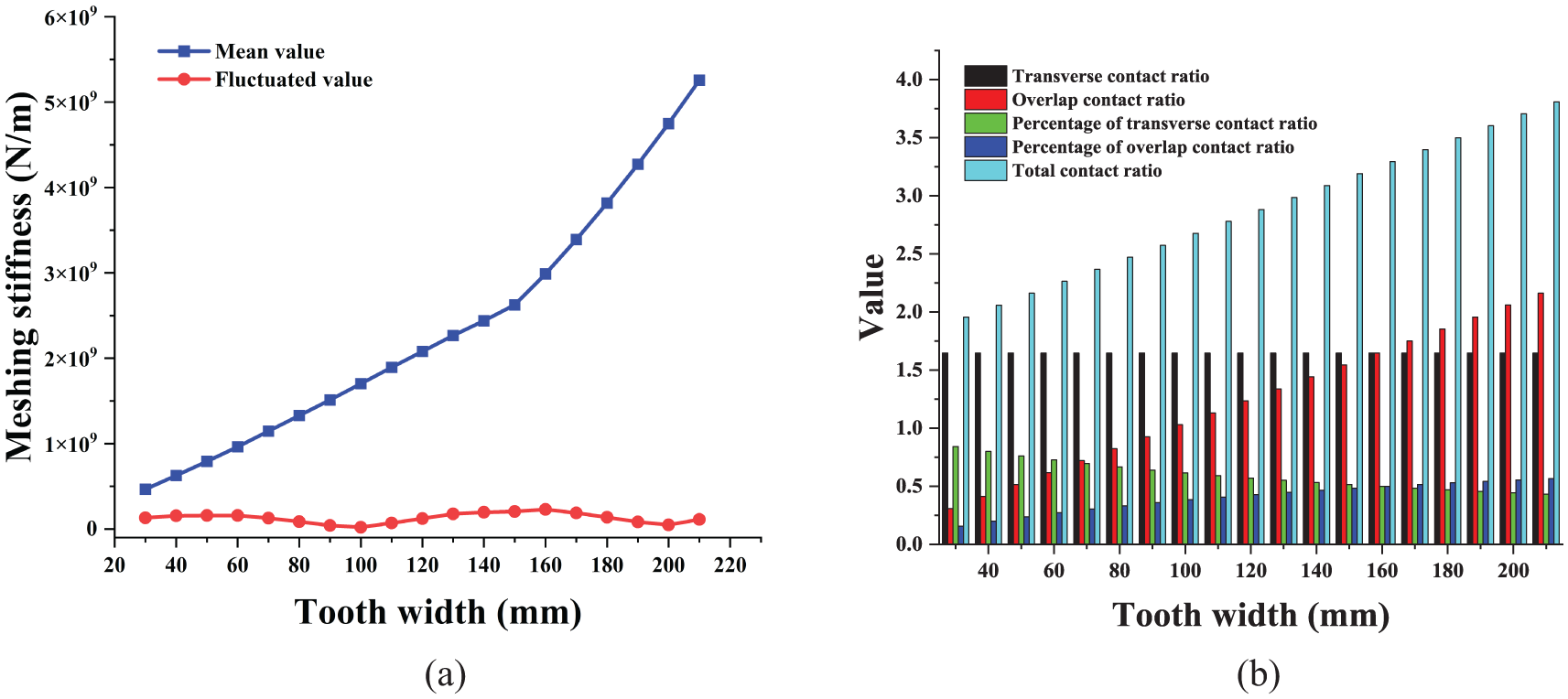
Variation of mean value, fluctuated value and contact ratio of meshing stiffness for different tooth widths: (a) change in mean and fluctuated value of the meshing stiffness and (b) change in contact ratio.
From Figures 9(a)–(f) to 11(b), it can be seen that the change in tooth width does not affect the transverse contact ratio, but the overlap contact ratio and total contact ratio increase monotonically with the increase of tooth width. The helical gear pair gradually transitions from single tooth and two tooth alternating meshing to three tooth and four tooth alternating meshing. Combining Figures 10 and 11(b), it can be seen that the proportion of overlap contact ratio to total contact ratio increases with the increase of tooth width, and the relative time for gear teeth to enter and exit meshing also increases accordingly. Due to the monotonic increase in the total overlap, the time for a single tooth to participate in meshing increases throughout the entire single tooth meshing process with the increase in tooth width, and the maximum values of single tooth meshing stiffness and the total meshing stiffness also monotonically increase. This is because the increase in tooth width reduces the contact deformation of the teeth, thereby improving the gear meshing stiffness. As can be seen in Figure 11(a) and (b), as the tooth width increases, the mean value of the meshing stiffness of the helical gears increases relatively slowly when the transverse contact ratio is greater than overlap contact ratio (
Effect of modulus on time-varying meshing stiffness of helical gears
Based on the basic parameters of gears in Table 1, calculate the time-varying meshing stiffness of helical gears with modulus of 4, 6, 8, 10, 12, and 14, as shown in Figure 12(a) to (f). The comparison of single tooth meshing stiffness at different modulus and the comparison of total meshing stiffness are shown in Figure 13(a) and (b). The average and fluctuation values of time-varying mesh stiffness are shown in Figure 14(a). The changes in transverse contact ratio, overlap contact ratio, and total contact ratio of helical gear pairs with different modulus are shown in Figure 14(b).
Time-varying meshing stiffness of helical gears with different number of gear modulus: (a)

Comparison of time-varying meshing stiffness of helical gears with different modulus: (a) comparison of the single tooth meshing stiffness and (b) comparison of the total meshing stiffness.

Variation of mean value, fluctuated value and the contact ratio of meshing stiffness for different modulus: (a) change in mean and fluctuated value of the meshing stiffness and (b) change in contact ratio.
From Figures 12 to 14(b), it can be seen that the change in gear modulus does not affect the transverse contact ratio of the gear, but the overlap contact ratio and total contact ratio decrease with the increase of gear modulus, and the relative time for gear teeth to enter and exit meshing also decrease accordingly. During the entire single tooth meshing process, the time for a single tooth to participate in meshing decreases with the increase of gear modulus, and the helical gear pair gradually decreases from alternating meshing of three and four teeth to alternating meshing of two and three teeth. From Figure 13(a), it can be seen that as the gear modulus increases, the maximum value of single tooth meshing stiffness of the gear will decrease. From Figure 14, it can be seen that as the gear modulus increases, the average meshing stiffness rapidly decreases when the transverse contact ratio is less than the overlap contact ratio (
Effect of pressure angle on the time-varying meshing stiffness of helical gears
Based on the basic parameters of gears in Table 1, calculate the time-varying meshing stiffness of helical gears with pressure angles of 15°, 16°, 17°, 18°, 19°, and 20°. The comparison of single tooth meshing stiffness at different pressure angles and the comparison of total meshing stiffness are shown in Figure 15(a) and (b). The average and fluctuation values of time-varying mesh stiffness are shown in Figure 16(a). The changes in transverse contact ratio, overlap contact ratio, and total contact ratio of helical gear pairs with different pressure angles are shown in Figure 16(b).

Comparison of time-varying meshing stiffness of helical gears with different pressure angle: (a) comparison of the single tooth meshing stiffness and (b) comparison of the total meshing stiffness.
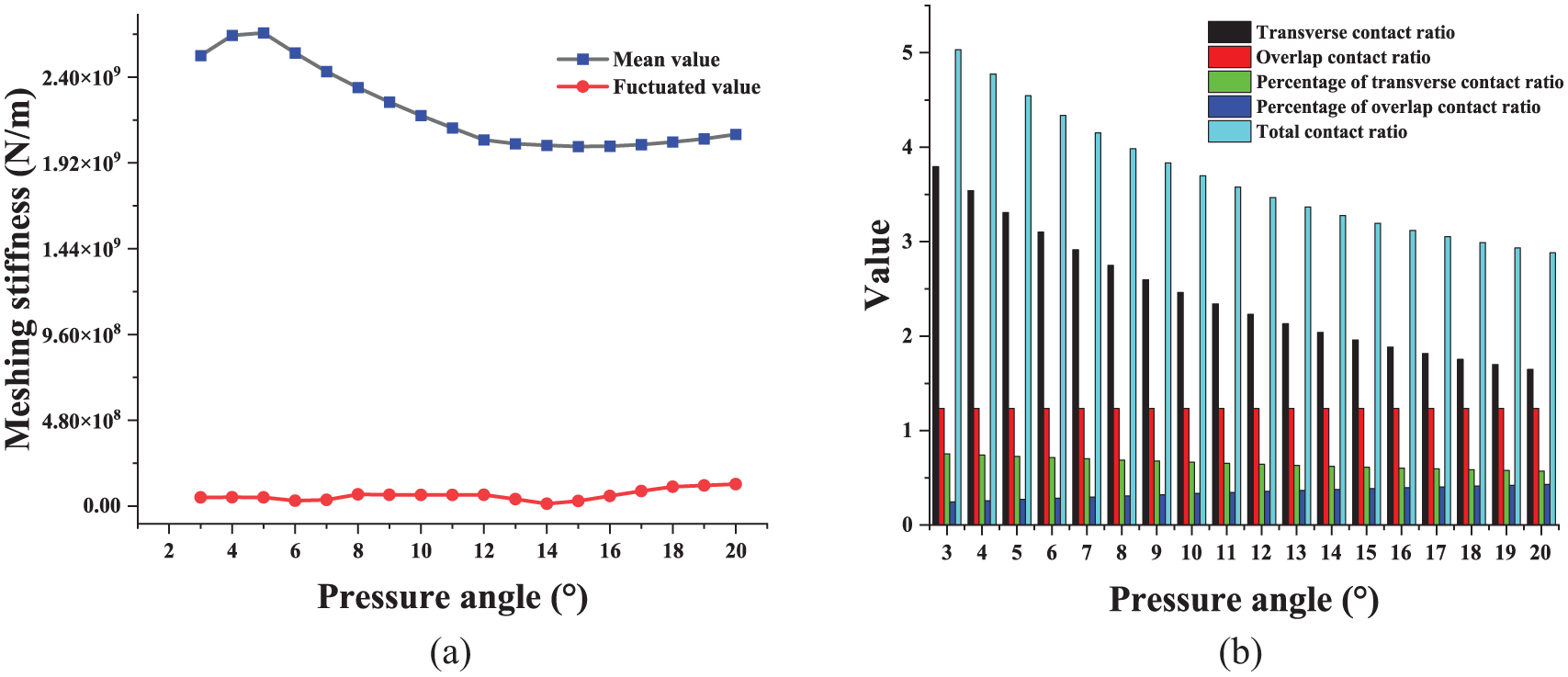
Variation of mean value, fluctuated value, and contact ratio of meshing stiffness for different pressure angle: (a) change in mean and fluctuated value of the meshing stiffness and (b) change in contact ratio.
From Figure 15(a), it can be seen that as the pressure angle increases, the helical gear tooth top becomes thinner, the tooth root becomes thicker, and the bending radius of curvature becomes larger, which in turn makes the tooth contact strength and the tooth root bending strength larger at the same time, and thus the maximum value of the helical gear single-tooth meshing stiffness increases. From Figure 16(b), it can be seen that the proportion of the overlap contact ratio in the total contact ratio increases, and the meshing time relatively increases. As the total contact ratio decreases with the increase of pressure angle, the single tooth meshing time becomes shorter. From Figure 16(a) and (b), it can be seen that with the increase of pressure angle, although the maximum value of single tooth meshing stiffness increases, the average value of total meshing stiffness does not decrease monotonically with the increase of pressure angle due to the decrease of total contact ratio, and the change of pressure angle does not affect the overlap contact ratio of helical gears. Therefore, the fluctuation value of the total meshing stiffness of helical gears is not significant.
Calculation of time-varying meshing stiffness of helical gears with root crack faults
Improved potential energy method
The tooth root crack is defined by the crack angle

Sliced view of a cracked helical gear.
From Figure 17, it can be seen that when a tooth root crack fault occurs in the gear, the length of the contact line on the working tooth surface at the same meshing position remains unchanged, and the Hertz contact stiffness of the gear teeth remains unchanged. The presence or absence of cracks does not affect the radial load on the teeth. Therefore, the calculation of axial compression stiffness is also the same as that of a healthy gear. In summary, for gear pairs with root crack faults, the time-varying meshing stiffness of the gear pair can be indirectly obtained by recalculating the bending stiffness and shear stiffness under crack conditions. When solving the time-varying mesh stiffness of helical gears with root crack faults, beam theory is still applicable. A cracked helical gear can be divided into multiple cracked spur gear slices, and the time-varying meshing stiffness of the cracked spur gear slices can be solved. Then, the stiffness of the spur gear can be accumulated and integrated. The helical gears with crack faults can be solved in four situations, and the corresponding slice cantilever beam models of cracked spur gears are shown in Figures 18 and 19. The slice models of spur gears with crack faults in cases 1 and 2 are shown in Figure 18(a) and (b); Situations 3 and 4 are shown in Figure 19(a) and (b).
(1) As in the case of Figure 18(a),

Sliced cantilever beam model of crack-failed helical gear for

Sliced cantilever beam model of crack-failed helical gear for
The inertia distance and cross-sectional area of the section of a cracked tooth at a distance


where,

Based on the equation and integration method described in Section “Improved calculation of time-varying meshing stiffness of healthy helical gears” of this article, the bending stiffness and shear stiffness of the faulty helical gear teeth under the condition of the situation 1 can be derived as follows:


(2) As in the case of Figure 18(b),
Since, the inequality

The stiffness of each part can be expressed as:

(3) As in the case of Figure 19(a),


(4) As in the case of Figure 19(b),


The total meshing stiffness of cracked gears can be solved by the following equation:
Based on the data in Table 1, take the crack depth q = 5 mm and solve it using MATLAB. The comparison between the time-varying mesh stiffness of helical gears with root crack faults and healthy helical gears is shown in Figure 20.

Comparison of time-varying meshing stiffness of healthy and faulty helical gears.
From Figure 20, it can be seen that the time-varying meshing stiffness of healthy and cracked gear pairs during the meshing process has almost the same trend, and the presence of cracks leads to a significant decrease in the local meshing stiffness of the gears. It can be found that the difference between the meshing stiffness curves of the faulty gear teeth is not significant at the initial moment of meshing by comparing the changes in meshing stiffness between healthy and faulty gears. As the cracked teeth gradually participate in meshing, the difference between the meshing stiffness curves becomes apparent, which is due to the greater load borne by the faulty teeth. When transitioning from three tooth meshing to two tooth meshing, the load borne by the faulty tooth reaches its peak, and at this time, the total meshing stiffness of the cracked helical gear decays most significantly. Based on the improved potential energy method, the time-varying mesh stiffness of the helical gear with faults was calculated for the other two groups of data. The calculation results are shown in Figure 21.

Comparison of time-varying meshing stiffness of two sets of faulty gears: (a)
As shown in Figure 21, compared with the traditional potential energy method, the time-varying meshing stiffness of helical gears with root crack faults based on improved energy calculation is consistent with the faultless meshing stiffness obtained by this method. Therefore, it can be proven that the theoretical formula for improving the time-varying meshing stiffness of faulty helical gears is more consistent with the actual values.
Analysis of the effect of crack parameters on time-varying meshing of helical gears
From Section “Improved potential energy method” of this article, it can be seen that the presence of root cracks has a significant impact on the time-varying mesh stiffness of helical gears. This section will explore the influence of the depth of tooth root cracks and the size of crack angles on the time-varying meshing stiffness of helical gears based on Section “Improved potential energy method.” The selected fault parameters are shown in Tables 4 and 5.
Dimensions of tooth root crack depth

Dimensions of tooth root crack extension angle v.

Based on the above data, the single tooth meshing stiffness and comprehensive meshing stiffness of the helical gear can be calculated at different fault parameters. Figures 22(a) and 23(a) show respectively the comparison of the meshing stiffness of helical gears at different crack depths and angles; Figures 22(b) and 23(b) show respectively a comparison of the rate of change of the minimum value of helical gear mesh stiffness under different crack depths and angles, and the rate of change of the minimum value of meshing stiffness can be expressed as:

where,
From Figure 22, it can be seen that the meshing stiffness decreases with the increase of crack depth, and the magnitude of the decrease increases. First of all, this is because the crack depth increases, participating in the meshing of the faulty gear in the crack at the stress concentration will increase, at the same time the local stress will become larger, resulting in a reduction in the gear load carrying capacity and the stiffness; secondly, as the depth of the crack approaches the centerline position of the gear, the gear crack will rapidly expand to the entire tooth profile, leading to tooth breakage faults in the helical gear; therefore, as the depth of the crack increases, the magnitude of stiffness reduction also increases. Figure 23 shows that the meshing stiffness decreases with the increase of crack angle, but the magnitude of its decrease also decreases. Compared with Figure 22, the influence of crack depth on the meshing stiffness of faulty helical gears is greater than that of crack angle.

Time-varying meshing stiffness and minimum variation of helical gears with different crack depths: (a) comparison of time-varying stiffness for different crack depths and (b) minimum rate of change of the meshing stiffness.

Time-varying meshing stiffness and minimum change rate of helical gears with different crack depths: (a) comparison of the time-varying stiffness and (b) minimum rate of change of at different crack spreading angles meshing stiffness.
Conclusion
In this paper, based on the literature, 4 the theoretical time-varying meshing stiffness of healthy helical gears and faulty helical gears containing root cracks is proposed to be calculated based on the improved potential energy method by taking into account that the root circle of helical gears does not overlap with the base circle as well as the angle of the transition circle of the gear root, and the effects of the basic parameters of healthy helical gears and the failure degree of faulty helical gears on the time-varying meshing stiffness are also analyzed. The specific conclusions are as follows:
(1) The simulation results based on KISSsoft software verify the correctness of the theoretical time-varying meshing stiffness formula of the improved potential energy method. The results show that the improved energy method is reasonable and the accuracy of the calculated helical gear meshing stiffness is about 5% higher than that of literature. 4 It is necessary to consider the non coincidence between the tooth root circle and the base circle, as well as the transition fillet of the tooth root circle when calculating the time-varying mesh stiffness of helical gears.
(2) The change of the basic parameters of helical gears will lead to the change of the contact ratio, and the change of the contact ratio of gears has a significant effect on the time-varying meshing stiffness of helical gears. The mean value of helical gear meshing stiffness increases slowly when transverse contact ratio is larger than overlap contact ratio; the mean value of stiffness increases rapidly when the transverse contact ratio is smaller than overlap contact ratio. The fluctuation value of meshing stiffness is in the local minimum value when overlap contact ratio is close to an integer; the fluctuation value of meshing stiffness is in the local maximum value when the value of total overlap is near an integer. The stability of gear system transmission is closely related to the fluctuation value of meshing stiffness. Therefore, in the actual design process of gears, it can be considered to adjust the overlap contact ratio to around integers, and try to avoid the total contact ratio around integers as much as possible to reduce system vibration.
(3) Changes in crack depth and angle lead to a local decrease in the time-varying meshing stiffness of helical gears. With the increase of crack depth, the local reduction of meshing stiffness is more obvious, and the magnitude of reduction increases; as the crack angle increases, the decrease in stiffness becomes more pronounced, but the magnitude of the decrease also decreases, compared to crack angle, meshing stiffness is more sensitive to changes in crack depth. It is necessary to detect the fault as soon as possible before the crack depth reaches 12.5 mm.
Footnotes
Handling Editor: Chenhui Liang
Declaration of conflicting interests
The author(s) declared no potential conflicts of interest with respect to the research, authorship, and/or publication of this article.
Funding
The author(s) disclosed receipt of the following financial support for the research, authorship, and/or publication of this article: This research was funded by basic scientific research projects of Liaoning Provincial Department of Education (JYTMS20230216), Liaoning Province Basic Research Projects of Higher Education Institutions (Grant No. LG202107), the construction plan of scientific research and innovation team of Shenyang Ligong University (SYLU202101).