
Abstract

The slip flow phenomenon caused by the gas floating seal in ultra-thin gas films and high-altitude rarefied gas environments occurs frequently. This study represents the first attempt to calculate the gas film floating force by considering the coupling relationship among the slip flow effect, the surface micro-grooves, and the eccentricity using a high-precision eight-node finite difference method based on the linearized Boltzmann equation for a spiral-grooved cylindrical gas seal. Furthermore, the influence of slip flow on the operational and groove parameters of the spiral-grooved cylindrical gas seal is investigated and discussed. Results show that the velocity gradient of the lubrication gas is reduced and the effect of the fluid hydrodynamic pressure is weakened because of slip flow, particularly in high-speed, low-pressure, and high-eccentricity fields. However, increases in groove depth, number, and length improve the gas film floating force, which strengthens the slip flow response in the grooves. Therefore, the slip flow reduces the gas film floating force, but when the groove depth exceeds 32 μm and the groove length is greater than 45 mm, the slip flow may become negligible. The results presented here provide a theoretical basis to broaden the application scope of dynamic seals in the aerospace field.
Introduction
The National Aeronautics and Space Administration (NASA) of the USA noted that improved seals in aerospace engines can result in an increase in net thrust of 9.7%, an increase in efficiency of 4.2%, and a reduction in the fuel consumption rate of 2.5%.1,2 Therefore, the performance of the seal determines the operational efficiency and the reliability of turbine machinery in aerospace applications. In addition, NASA proposed a new spiral-grooved cylindrical gas seal, which uses a thin gas film thickness (3–9 μm) and surface micro-textures to improve the gas film pressure. 3 However, there may be a rarefied gas problem that occurs in the seal when operating at high altitudes. The slip flow effect must therefore be considered for this spiral-grooved cylindrical gas seal because the Knudsen number is greater than 0.01 in this case.
At present, the study of slip flow mechanisms is mainly based on molecular dynamics methods4–8 and microfluid mechanics. However, a high computational capacity and an advanced supercomputer are required for these approaches. Therefore, by combining the latter method with consideration of film lubrication theory, Burgdorfer 9 analyzed the effect of the molecular mean free path on the performance of hydrodynamic-pressure gas bearings using a modified Reynolds equation with a first-order slip velocity boundary. In subsequent studies, researchers developed a variety of velocity slip boundaries, including the second-order slip velocity boundary condition proposed by Hsia and Domoto. 10 Mitsuya 11 then modified the second-order velocity slip boundary condition proposed by Hsia and Domoto to propose a 1.5-order slip velocity boundary. Subsequently, Bahukudumb and Beskok 12 presented a semi-analytical model, but their application scope was limited and the solution process was cumbersome. Fukui and Kaneko 13 then established the Bhatnagar–Gross–Krook calculation model based on the Boltzmann equation. Their research results proved that the model was suitable for performance analysis of gas slip flows with arbitrary Knudsen numbers and thus had an important impact on subsequent studies. However, in the models described above, the calculation process for the Poiseuille flow coefficient was highly complex. Huang 14 fitted the calculation results from the Boltzmann model and then presented an analytical equation for calculation of the Poiseuille flow coefficient. Using a large number of slip flow models, Gu et al. 15 then derived an improved Reynolds equation that combined multiple slip models with film lubrication theory. During the process of solving for the Poiseuille flow coefficient, Huang 14 presented finite difference method (FDM) schemes for the different types of hydrodynamic pressure lubrication calculation problems. Childs and Leland 16 used the FDM to study the static and dynamic characteristics of annular floating seals for rocket turbopumps. Nagai et al.17,18 used a five-node FDM to analyze the static and dynamic characteristics of liquid annular seals with spiral grooves for use in aviation turbopumps. Other researchers19–21 provided comprehensive considerations of the structural parameters used in the FDM to perform thermoelastic lubrication simulations and also described the gas film temperature distribution. Additionally, many studies of gas floating seals have focused on improving the structures of the seal support and seal surface to increase the load capacity. Yamakiri et al. 22 studied the seal surface microstructure and confirmed that control of the surface microstructure provides a highly effective method for improvement of the hydrodynamic pressure effect. Their results showed that the surface microstructure can store lubricating gases or liquids, although the improvement in the load capacities was more significant when using strip grooves with small pitches and dimples for small seal gaps. 23 Kovalchenko et al. 24 used lasers to fabricate different groove types and found that the hydrodynamic pressure effect in these grooves generated an additional load capacity.
As indicated by the studies described above, there has not been a comprehensive study to date that provides a detailed explanation of the coupling effects of the surface groove structure, the eccentricity, and the slip flow mechanism on the floating force of a micro-grooved cylindrical gas seal. In this paper, a theoretical model (the linearizing Boltzmann equation/Frenkel-Kontorova (F-K) model) for an improved Reynolds equation is combined with the flow factor and derived using the slip flow effect, the surface spiral-grooved structure, and the eccentricity of a micro gap for a spiral-grooved cylindrical gas seal based on the linearized Boltzmann equation. The gas film pressure and the floating force are determined by solving the nonlinear Reynolds equation using a high-precision eight-node FDM and the Newton–Raphson iterative method to eliminate the computational divergence of grooved-step changes and ultra-thin gas films. The gas film floating force of the F-K model is compared with those of other models from the existing literature. The gas film pressure and the floating force are then investigated to determine the internal correlation among the slip flow, the operating parameters, and the groove parameters.
Numerical Solution
Geometric model
The spiral-grooved cylindrical gas seal is shown schematically in Figure 1, where the outer surface of the rotating ring has a hydrodynamic-pressure micro-spiral-groove. The eccentricity of the floating ring causes the sealing gap to form a wedge shape; as a result, the gas film between the floating ring and the rotating ring creates a hydrodynamic pressure because of the high operating speed, which then generates the gas film floating force that supports the floating ring. The gas film thickness and the groove depth are both of the order of microns.

Schematic diagram of the new spiral-grooved cylindrical gas seal.
Fluid control model
The main feature of the spiral-grooved cylindrical gas seal is that the gas film is very thin. Therefore, any pressure variations along the gas film thickness direction can be neglected, and the number of variables associated with the fluid velocity and fluid pressure are reduced. To simplify the governing equations of the flow velocity and pressure further, the following major assumptions are made in this work:
(1) The fluid is a Newtonian fluid, the flow is laminar, and the viscous forces are much greater than the body forces.
(2) Pressure and viscosity changes are ignored in the gas film thickness direction.
(3) The section radius is much greater than the film thickness, and the effects of the gas film curvature are ignored.
Reynolds equation under nonslip flow conditions
Based on consideration of the structural characteristics of the spiral-grooved cylindrical gas seal shown in Figure 1, the cylindrical Reynolds equation under nonslip flow conditions is:

where z is the axial coordinate, θ is the circumferential coordinate (rad), R represents the outer radius of the rotating ring (m), μg represents the dynamic viscosity of the lubricating gas (N·s/m2), ω is the angular velocity of the rotating shaft (rad/s), p is the gas pressure (Pa), and h is the gas film thickness (m).
The following dimensionless variables are then defined:
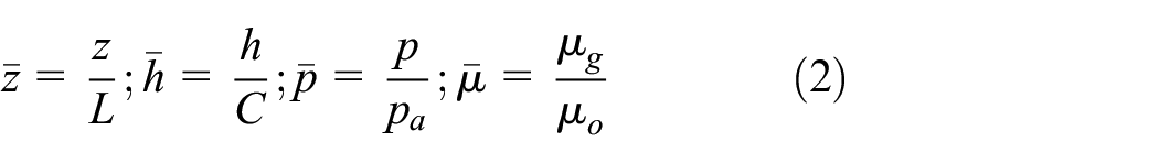
where L is the floating ring length (m), C is the initial gas film thickness (m), pa is the ambient pressure (on the low pressure side; Pa), and μ0 is the ambient viscosity of the lubricating gas (N·s/m2).
The dimensionless Reynolds equation for the spiral-grooved cylindrical gas seal is then given as


where
Modified Reynolds equation under F-K slip flow conditions
Based on the linearized Boltzmann equation and the slip flow effect, the dimensionless modified Reynolds equation for the spiral-grooved cylindrical gas seal is (this equation is subsequently referenced as the F-K model for short in the rest of the paper):

By considering the effect of the slip flow, the dimensionless Poiseuille flow coefficient QMGL can then be expressed as:

where

Gas film thickness model
As shown in Figure 1, the number of spiral grooves is nc, the length of each spiral groove is lc, the groove depth hc is the radial groove depth of the rotating ring surface, and the spiral angle is represented by β. The gas film thickness h is determined using the circumferential angle θ, the eccentricity ε, and the groove structure.
First, the gas film thickness for the non-groove area is derived using:


where e is the distance between the center of the floating ring and the center of the rotating ring, i.e., it is the eccentric distance.
Because e/R1 <<1,
Therefore,


where C = R1−R is the gap between the floating ring and the rotating ring, i.e., it is the initial gas film thickness.
The rotating ring surface is then divided into groove and non-groove areas, as shown in equation (12):

Using the dimensionless variables defined in equation (2), the nondimensional gas film thickness

where
Discretization and Solution of Computational Domain
The spiral-grooved cylindrical gas seal has an eccentric and micro-grooved structure, and a pressure difference exists between the two ends of the seal. Therefore, the calculation domain used for the gas film must be meshed completely. Simultaneously, because the Rayleigh step and the wedge shape cause calculational divergence for the gas flow, the eight-node FDM is used to discretize and solve equations (3) and (5), as shown in Figure 2. Furthermore, the extremely thin gas film and the slip flow result in a larger compressibility coefficient, which can cause inconstancies in the calculation results. Therefore, an upwind scheme must be combined with the eight-node FDM and the Newton–Raphson iterative method to calculate the gas film pressure and the floating force under slip flow conditions.

Schematic diagram showing the eight difference nodes.
According to equation (5), the dimensionless F-K model of the spiral-grooved cylindrical gas seal can be written in the following difference form:

where
q can also be expressed in a difference form, as follows:

The discretization scheme for the dimensionless Reynolds equation of the spiral-grooved cylindrical gas seal under nonslip flow conditions is provided in Appendix A.
Verification of Grid Independence and Calculation Example
Verification of grid independence
To examine the effects of the grid comprehensively in the axial and circumferential directions of the seal, the following eight groups of node densities are used to discretize the calculation domain: 52 × 25, 52 × 50, 104 × 50, 104 × 100, 104 × 200, 208 × 200, 208 × 300, and 260 × 300 nodes. The eight group grids are used to determine an estimate to enable calculation of the gas film floating force from the F-K model of the spiral-grooved cylindrical gas seal. Table 1 shows the initial structural and operational parameters of the spiral-grooved cylindrical gas seal. The relationship between the floating force and the grid density is illustrated in Figure 3. Generally, as the grid density increases, the floating force also increases. The effect of the circumferential grid density is greater than that of the axial grid density in this case. This also indicates that the Rayleigh step effect formed by the discontinuous groove-step in the circumferential direction has a significant effect on the calculation accuracy. When the number of grid nodes reaches 208 × 300, the change in the floating force is no longer obvious with increases in grid size. The 208 × 200 grid was therefore selected for use in the following study based on consideration of the calculation accuracy and efficiency.
Initial structural and operational parameters of the spiral-grooved cylindrical gas floating seal.


Verification of the grid independence.
Boundary condition
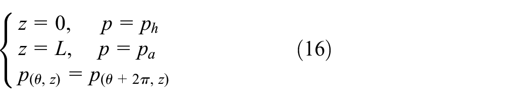
The pressure of the spiral-grooved cylindrical gas seal is continuous in the circumferential direction. The pressures at the inlet and outlet ends of the seal are the pressure of the sealing medium and the ambient pressure, respectively. Therefore, the boundary conditions can be given as follows:
Iterative method
The solution is solved using the successive over-relaxation iteration method, where the iteration format is as follows:

where
At the beginning of the iteration, because of the large error involved, a small value of β should be used, with the value being set at 0.1 here. As the iterations continue, β increases gradually to reach 1. During the numerical iteration process, the following equation is used to judge whether the convergence condition has been satisfied:

where err is the error convergence accuracy, which was set at 1×10⁻⁶ and Eij is the node residual; the specific expressions are provided in Appendix B.
Experimental system
The basic working principle of the experimental system is described as follows. The transmission system powers the sealed system, which is connected to the gas supply system, thus realizing operation of the floating spiral groove cylindrical seal. The sealing pressure and sealing speed can be adjusted freely. Subsequently, the test system collects signals for measurement of the gas film pressure, the rotational speed, and the sensor leakage; the experimental system is shown in Figure 4.

(a) Gas supply system, (b) the sealing system, and (c) the test system.
Transmission system
The transmission system drives the floating micro-groove cylindrical seal. As a result of the micro-level gap in the gas film, the transmission system requires both high precision and advanced stability. Therefore, a high-speed motor with power of 8.5 kW and a maximum rotational speed of 50,000 r/min was selected as the direct drive source.
Gas supply system
The gas supply system consists of an inlet pipeline and an outlet pipeline. This system can provide the required sealing pressure over the range from 0.1 to 3.5 MPa and can collect the gas that leaks from the seal, as shown in Figure 4(a). Simultaneously, the sealing pressure is regulated using a gas pressure reducing valve, and metal floating flow meters are used to observe and transmit data for both the inlet and exhaust gas flow rates.
Sealing system
The floating micro-groove cylindrical seal uses a symmetrical structure (back-to-back). The rotating ring and the floating ring are made from SiC and graphite, respectively, as illustrated in Figure 4(b). The reasons for these choices are given as follows:
The axial unbalanced force of the sealing device is eliminated, thus enhancing the stability of the experiment.
Leakage may occur at the bearing end of the high-speed motor; therefore, a double-sided structure was used to reduce the possibility of gas film contamination.
The symmetrical structure of the seal is more convenient for installation and disassembly.
Testing principle of gas film pressure
The pressure sensor is used to measure the gas film pressure and the collected gas film pressure is then converted into the gas film opening force via the LabVIEW program (National Instruments). Because the gap between the floating ring and the rotating ring is on the micrometer scale and it is eccentric, this leads to challenges when responding to pressure signals. Therefore, the pressure sensor is installed using the embedding method. First, five holes with a width of 3.8 mm and circumferential spacing of 72° are processed on the outer surface of the floating ring at an axial spacing of 3.2 mm. The pressure sensors are subsequently installed inside these holes and bonded firmly in place. The inner surface of the floating ring is ground to ensure that its surface is as flush as possible with the probe surface. Finally, pressure is introduced inside the sensor to measure the pressure of the gas film in the cylindrical flow field using the system shown in Figure 4(c).
Groove engraving
The general groove shape and groove morphology may be influenced by the laser parameters, including the laser flux, wavelength, and pulse duration, in addition to the focusing system. In this study, the laser beam is simply focused and scanned on the sample surface in a process known as direct laser writing, and a numerical control system is used to drive the laser system. Based on the spiral groove structure calculated from the theory described earlier, we transferred the spiral groove pattern from the computer-aided design system to the laser system. We used a circular engraving method in combination with a high-precision motor to ensure synchronous engraving in both the circumferential and axial directions at a pulse frequency of more than 20 kHz.
The grooving process is described in the following.
The spiral groove is embossed using a circular engraving fabricated by a laser operating at 80% of maximum power to ensure that the desired depth is realized. When the depth of the spiral groove is reached, the laser power is then reduced from 80% to 50%, and the groove area is scanned and treated to rectify any unevenness occurring at the base of the spiral groove.
The laser power is then set to 20%, and the relevant parameters are adjusted such that the laser beam treatment serves as a polishing technique, which leads to significant improvements in the roughness occurring at the base and sides of the spiral groove.
Upon completion of the steps above, an ultrasonic cleaner and a drying oven are prepared and used to clean and dry the spiral groove sample, respectively.
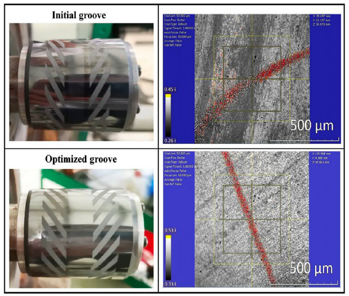
The ZeGage system (Zygo) is used to scan the 3D surface profile of the sample groove. The initial roughness at the base of the groove was 0.880 mm and the optimized unevenness at the base of the groove was 0.917 mm. In addition, the initial groove depth was 6.049 mm and the optimized groove depth was 6.045 mm, as shown in Figure 5.

Groove morphology of the specimen.
Experimental validation
Figure 6 illustrates the variations in the gas film opening force with respect to rotation speed and pressure. First, for both the initial and optimized grooves, the experimental opening force for the gas film always increases in proportion to the rotation speed. More importantly, the rate of increase in the gas film opening force escalates gradually within the 10,000- to 32,000-r/min rotation speed range. Additionally, the experimental opening force for the optimized groove always exceeds that of the initial groove. However, as the rotation speed increases, the force gap observed between the optimized groove and the initial groove expands further. Throughout Figure 6(b), the effect of the pressure on the gas film force mirrors that of the rotation speed shown in Figure 6(a).

Gas film opening forces from experiment and theory versus (a) speed and (b) pressure.
Regardless of whether the optimized groove or the initial groove is considered, the tested opening force intensifies sharply with increasing pressure, particularly within the 0.2 to 1.0 MPa range. Furthermore, the gas film opening force for the optimized groove is greater than that for the initial groove.
Combining Figure 6(a) and (b) allows the following conclusions to be drawn.
The theoretical results are consistent with the experimental trends, thus affirming the feasibility and the scientific nature of the proposed theoretical model.
The optimized groove does indeed stimulate the gas film pressure more strongly, which produces a subsequent enhancement in the lubrication performance of the floating cylindrical seal.
Regardless of any variations in the rotation speed or pressure, the theoretical opening force values are always higher than the actual experimental data. Furthermore, there are noticeable fluctuations in the experimental data, which may be related to equipment vibrations, the sensor response, and flow excitation, among other factors.
The results in Figure 6 have already demonstrated that optimization of the groove causes the gas film opening force to be enhanced. Subsequent to the tests, the floating micro-groove cylindrical seal was disassembled, and the surfaces of the rotating rings with both the initial and optimized grooves were analyzed post-experimentally. Figure 7 illustrates the wear patterns and morphologies on the rotor surfaces.
Surface profiles of the rotating rings after running.
Figure 8 illustrates the variations in the leakage rate with respect to the rotation speed and the pressure. Initially, as the rotation speed increases for both the initial and optimized grooves, the experimental leakage rate gradually decreases; however, at speeds above 28,000 r/min, the leakage rate then remains stable. Moreover, within the speed range from 10,000 to 32,000 r/min, the experimental leakage rate for the optimized groove remains consistently higher than that for the initial groove, as depicted in Figure 8(a). Observation of Figure 8(b) shows that the influence of pressure on the leakage rate is entirely distinct from the effect of the rotation speed shown in Figure 8(a).
In both the initial and optimized grooves, the leakage rate escalates rapidly across the entire pressure range (0.2–2.4 MPa).
The experimental leakage rate for the optimized groove is lower than that for the initial groove, but within the range for the low-pressure regime (0.2–0.6 MPa), the optimized groove does not show any significant advantage.

Leakage rates from experiments and theory versus (a) speed and (b) pressure.
In summary, the impact of the pressure on the grooves is far greater than that of the rotation speed, which indicates that the sealing pressure plays a more pivotal role than the speed in the sealing operation. An increase in sealing pressure implies the presence of a larger pressure differential that subsequently enhances the axial gas velocity. However, an increase in the rotation speed elevates the shear rate of the gas, which leads to a reduction in the leakage rate. Regardless of any changes in the rotation speed or pressure, the theoretical leakage rate trend aligns well with the measured experimental data, although the theoretical results are slightly lower in magnitude.
Verification for computation program and model
To verify the gas floating force determined in this paper, the calculation results from the no-slip flow and F-K models are compared with previously reported experimental results, 25 and the relevant parameters are listed in Table 2. Figure 9 shows a comparison between the calculated results and those from the experimental literature. 25 The calculated results agree closely with the experimental results. In particular, the calculation results from the F-K model are closer to the experimental results than those from the no-slip flow model. This is because the grooved cylindrical gas seal is prone to slip flow, which then reduces the floating force of the gas film versus the thin film thickness and high rotational speeds. Therefore, the F-K model is more accurate for spiral-grooved cylindrical gas seals for turbine machinery in aerospace engineering applications.
Experimental parameters from the literature. 25


Comparison of the calculated results with the experimental results from the literature. 25
Results and Discussion
Gas film pressure in no-slip flow and F-K models
From the parameters listed in Table 1, the gas film pressure contour maps of the spiral-grooved cylindrical gas seal were drawn as shown in Figure 10. Both gas film pressure maps are distributed in a zigzag pattern in the circumferential direction, and the gas film pressures of the two models in the axial direction reach peaks at the end of the spiral groove because of the pumping capability of the spiral groove located on the rotating ring surface. This pumping capability propels the gas from the groove toward the groove step, which causes flow blockages and creates a step effect, thereby generating an abrupt change in the gas film pressure. Comparison of Figure 10(a) and 10(b) shows that the gas film pressures for the slip flow in the groove and non-groove areas are lower than the corresponding pressures determined without the slip effect. This difference occurs because the slip boundary reduces the velocity gradient in the fluid between the floating and rotating rings. When the gas film is at 180° in the circumferential direction, the gas film thickness is at its smallest, and the slip flow has a greater impact on the gas film pressure as a result. In addition, the slip flow is strengthened further in the groove-step area of the spiral groove in the axial direction.

Pressures of the gas film in (a) the nonslip flow model and (b) the F-K model.
Floating force of nonslip flow and slip flow under operating conditions
Figure 11 shows the variations in the gas film floating force with respect to the rotational speed (10,000–50,000 r/min) and the sealing pressure (0.3, 0.5, 0.7 and 0.9 MPa) under the conditions in Table 1. The gas film floating forces for the nonslip flow and the slip flow increased with increasing rotational speed, and the gas film floating force without the slip flow is greater than that with the slip flow. Furthermore, the calculation results for the nonslip flow and F-K models showed increasing differences. For example, at a sealing pressure of 0.3 MPa and a rotational speed of 10,000 r/min, the floating forces of the nonslip flow model and the F-K model are 618.80 and 594.99 N, respectively. However, at 0.3 MPa and 50,000 r/min, the corresponding floating forces of the nonslip flow model and the F-K model are 1334.28 and 1158.14 N, respectively. The velocity gradient of the lubricating gas is reduced and the effect of the fluid hydrodynamic pressure is weakened because of the slip flow. Additionally, the floating force of the spiral-grooved cylindrical gas seal also decreased. Therefore, the high rotational speed could not prevent the slip flow from reducing the floating force and thus increasing the difference between the floating forces with and without the slip flow. In addition, the difference between the gas film floating forces of the nonslip flow model and the F-K model at 0.3 MPa is greater than that at 0.5 MPa. This difference occurs because at lower pressures, the hydrodynamic pressure effect of the spiral-grooved cylindrical gas seal is poor, which causes the gas film shear rate to increase and exhibit strongly nonlinear characteristics. The characteristics of the gas film have also been verified under low pressure conditions.26,12

Variations in the floating forces of the gas film with respect to rotational speed and pressure in the nonslip flow model and the F-K model.
Floating force of nonslip flow and slip flow versus eccentricity and gas film thickness
Figure 12 shows the variations in the floating force of the gas film versus the eccentricity (0.1–0.9) and the gas film thickness (4, 5, 6, 7 and 8 μm) under the conditions in Table 1. Greater eccentricity corresponds to a higher floating force. This holds because the wedge that forms between the floating ring and the rotating ring becomes more prominent with increasing eccentricity, which then leads to enhancement of the hydrodynamic pressure effect and improves the load capacity of the seal. When the gas film thickness is lower and the eccentricity is higher, there is a significant difference between the gas film floating force with slip flow and that without slip flow. This indicates that when the gas film is in the slip flow state, a thinner gas film leads to a greater slip flow effect; meanwhile, when the eccentricity increases, the gas film thickness distribution becomes more uneven, which leads to a higher variation rate in the gas flow velocity and strengthens the effect of the slip flow on the floating force further. With increasing gas film thickness, the effect of the slip flow on the gas film floating force decreases gradually. For example, at a gas film thickness of 4 μm and an eccentricity of 0.9, the difference between the floating forces for the gas films of the nonslip flow model and the F-K model is as high as 14.4%, whereas with the gas film thickness of 8 μm and an eccentricity of 0.9, the difference between the floating forces of the gas films in the nonslip flow model and the F-K model is only 6.5%.

Variations in the floating forces of the gas film with the eccentricity and the gas film thickness in the nonslip flow model and the F-K model.
Effects of groove parameters on floating force in nonslip flow and slip flow
Groove depth
Based on the conditions in Table 1, Figure 13 shows the variations in the gas film floating force in the nonslip flow model and that in the F-K model at groove depths of 2 to 32 μm. The gas film floating force in the nonslip flow model is always greater than that in the F-K model. Over the groove depths from 2 to 18 μm, the gas film floating forces in the nonslip flow model and those in the F-K model increase with increasing groove depth, and the difference between the floating forces in the nonslip flow model and the F-K model increases. This difference increases because the increase in the groove depth causes a corresponding increase in the gas film thickness in the grooved areas, which results in a corresponding increase in the gas film thickness variation rate in the circumferential and axial directions of the spiral-grooved cylindrical gas seal. Additionally, the gas pumping capacity within the grooves and the gas film pressure are both improved, thus causing the pressure gradients p/z in the axial direction and p/θ in the circumferential direction to increase, which further enhances the slip flow effect. However, in the process with groove depths ranging from 18 to 32 μm, because of the limitations of the gas viscosity, the floating force in the nonslip flow could not continue to increase with increasing groove depth; however, an increase in the groove depth means an increase in the gas film thickness, which leads to a transition for the gas from the slip flow state to the nonslip flow state. Therefore, the floating force increases continuously under the F-K model conditions. The phenomenon described above shows that the groove depth has an effect, regardless of whether the seal is in the slip flow or nonslip flow condition. When the groove depth is greater than 18 μm, the seal condition changes from slip flow to nonslip flow. In addition, it is speculated that the floating force results with and without slip flow converge when the groove depth is more than 32 μm, as illustrated in Figure 13.

Variations in the floating forces with groove depth for the nonslip flow model and the F-K model.
Number of grooves
Based on the conditions given in Table 1, Figure 14 shows the variations in the gas film floating force in the nonslip flow model and the F-K model versus the number of grooves in the range from 4 to 36 grooves. The gas film floating force in the nonslip flow model and that in the F-K model both reach a maximum when the number of grooves is 14. The presence of too many grooves increases the discontinuity of the gas film thickness in both the circumferential and axial directions and results in the occurrence of a pressure step in the surface of the rotating ring. Therefore, when the number of grooves exceeded 14, the floating force decreased. As the number of grooves increased from 4 to 36, the floating force in the nonslip flow model remained larger than that in the F-K model.

Variations in the floating forces of the gas film versus the number of grooves in the nonslip flow model and the F-K model.
Groove length
Based on the conditions given in Table 1, Figure 15 shows the variations in the gas film floating force in the nonslip flow model and the F-K model when the groove length ranges from 5 to 50 mm. As the groove length increases from 5 to 50 μm, the floating force in the nonslip flow model remains higher than that in the F-K model, and the difference between the floating forces for those two models initially increases and then decreases. At the groove lengths of 5 mm and 50 mm, the floating forces in the nonslip flow model and the F-K model are the same. The floating forces in the two models both peak at the same groove length of 30 mm. The phenomenon above can be explained as follows. 1) The increase in the groove length enhances the pumping capacity of the spiral groove and is also conducive to accumulation of the lubricating gas in the grooved area, thereby increasing the gas film floating force; 2) the increase in the groove length causes a corresponding increase in the hydrodynamic pressure effect in the grooves, which strengthens the slip flow response in the groove, thereby further weakening the floating force in the F-K model; 3) when the groove length exceeds 30 mm, the groove length ratio rises above 60%, which greatly increases the gas film thickness in the axial direction, and subsequently leads to gradual expansion of the lubricating gas in the groove, thereby reducing the floating force directly; 4) when the groove length ratio is less than 10% (groove length < 5 mm) and when the groove length ratio is greater than 90% (groove length > 45 mm), the slip flow can become negligible.

Variations in the floating forces of the gas film versus the groove length for the nonslip flow model and the F-K model.
Conclusions and Future Work
A spiral-grooved cylindrical gas seal is proposed for use in turbine machinery in aerospace applications. To provide a solution to the rarefied gas phenomenon caused by operation of the seal at high altitudes, high speeds, and low film thicknesses, an F-K model is built by considering coupling of the slip flow, the surface spiral groove, and the eccentricity. Then, the gas film floating force is discussed with respect to the operating and groove parameters using both the nonslip flow model and the F-K model. The following conclusions were obtained:
(1) The pressure fluctuations in the gas film resulted from (a) the hydrodynamic pressure effect caused by the blockage of and steps in the spiral groove, and (b) the convergent wedge effect caused by the eccentricity in the spiral-grooved cylindrical gas seal.
(2) The slip flow is worthy of consideration in the design of a spiral-grooved cylindrical gas seal with a low gas film thickness when operating under low pressure, high eccentricity, and high rotation speed conditions. In addition, the slip flow can reduce both the gas film pressure and the floating force.
(3) Increases in the groove depth, the number of grooves, and the groove length can cause an increase in the hydrodynamic pressure effect in the groove, which strengthens the slip flow response in the groove. The gas film floating force reaches a maximum at a groove number of 14 and a groove length of 30 mm. When the groove parameters exceed specific limit values (groove depth > 32 μm and groove length > 45 mm), the slip flow can become negligible.
The current F-K model presented here does not consider the influence of thermo-mechanical coupling deformation of the sealing ring on the gas film, and it also does not consider the effects of the sealing ring’s surface morphology on the sealing performance. In future work, based on a combination of thermo-elastic hydrodynamic lubrication theory and the micro-morphologies of the surface and the groove bottom, the influence of the slip flow on the dynamic characteristics of the seal will be analyzed in a more comprehensive manner.
Footnotes
Appendix A
The dimensionless Reynolds equation of the spiral-grooved cylindrical gas seal (equation (3)) can be written in a difference form:
With simplification, the equation above can be written in the following form:
Appendix B
where
Handling Editor: Chenhui Liang
Declaration of conflicting interests
The author(s) declared no potential conflicts of interest with respect to the research, authorship, and/or publication of this article.
Funding
The author(s) disclosed receipt of the following financial support for the research, authorship, and/or publication of this article: The work presented in this paper was supported by the National Natural Science Foundation of China under Award No. 51905480, by the Science and Technology Innovation 2025 Major Projects, China under Award Nos. 2020Z112 and 2018B10006, and by the Ningbo Natural Science Foundation under Award Nos. 2019A610161 and 202002N3082.