
Abstract
Aiming at the problems that a V-shaped clamp is easy to crack, wrinkle, and springback in the stamping process, a method to improve forming quality by setting the best stamping process parameters is put forward in this paper. The stamping process of the V-shaped clamp was simulated by using the software of ABAQUS, which showed that the stamping process parameters, such as friction coefficient, stamping speed, and mold gap, can affect the forming quality. The optimal combination of stamping process parameters was obtained through an orthogonal experiment. Simulation, profile dimensional measurement, and Fuji paper test were conducted to evaluate and examine the quality of V-shaped clamps before and after optimization. According to the findings of the study, the stamping speed is the main factor affecting the simulation results. The comprehensive effect of the maximum thinning rate, maximum thickening rate, and maximum springback is the best with the stamping speed of 10.00 mm·s−1. The ideal specifications for the stamping process are a 0.16 friction coefficient, a 10.00mm·s−1 stamping speed, and a 2.20 mm mold gap. Process parameter modification can greatly increase the dimensional accuracy and mechanical properties of molded parts.
Keywords
Introduction
The vehicle exhaust filtration system needs to be updated further in light of the China VI vehicle emission regulations. For the sealing connection structure of several pipes in a restricted space, stringent criteria are made in the context of automotive miniaturization and lightweight. 1 V-shaped clamps have gained widespread acceptance in the pipeline connection of vehicle exhaust treatment systems due to their excellent sealing performance, flexibility, and compact design.
The production experience has proved that proper stamping process parameters can effectively prevent the occurrence of forming defects. Using the finite element method to analyze the forming process and improve the quality of formed parts, scholars at home and abroad have done a lot of relevant work. Through the finite element method, Panthi, Dong, and Lin examined the formability and springback of the sheet metal forming process.2,3 During the forming process of single-layer and multi-layer thin plates, a strategy to optimize the variable blank holder force (BHF) trajectories was proposed by several researchers who studied the effect of BHF on tensile cracking and wrinkling.4–6 The effects of blank holder gap and stamping speed on the formability of cup-shaped components were investigated by Chen and Yang, respectively.7,8 Based on the findings of these research, it is clear that the forming process can be accurately analyzed by the finite element approach. However, they only studied the influence of a single factor on the quality of molded parts. The impact of numerous parameters on the molding process must be taken into account during real production.
Numerous researchers developed the finite element model and used orthogonal tests to assess the effects of process variables such as die corner radius, BHF, blank holder spacing, friction coefficient, mold gap, and stamping speed.9–12 Using the response surface approach as the basis, the researchers created a multiple regression model with the damage value of molded parts as the target and BHF, stamping speed, mold gap, and die corner radius as the influencing factors.13,14 Numerous studies have discovered that the mold structure and shape of molded parts limit the influence of process parameters on molding quality and that the influence varies. Accordingly, it is important to study each type of molded part independently. Although the impacts of many aspects on the quality of molded parts have been considered in these studies, the research object has no reference value for molded parts with complex shapes due to its simple structure, low molding difficulty and less prone to molding defects. V-shaped clamps were used as the research object in Wu et al.’s study of the impact of regional friction coefficient on forming parameters. 15 However, in actual production, the friction coefficient is affected by factors such as the material of the contact surface, surface lubrication state, positive pressure, and relative motion speed, which can lead to instability. The actual forming impact under working conditions differs significantly from the modeling results. By contrast, the outcomes of numerical simulation with multi-factor correlation analysis will be more precise and more closely resemble the actual production conditions.
This paper creatively proposes a method to determine the optimal process parameters through finite element analysis to improve the quality of molded parts, which is different from the traditional mold repair and multiple stamping processes, reducing the cost and simplifying the production process. The method is based on the complex structure of the V-shaped clamp and the interaction of many factors in production. The effects of the stamping process parameters (friction coefficient, stamping speed, and mold gap) on the rate of thinning, rate of thickening, and rate of springback of formed parts are examined. And the ideal combination of stamping process parameters is established using ABAQUS for numerical simulation. 16 The rationality of the simulation results is verified in actual manufacturing by profile dimensional measurement and Fuji paper test. It provides a basis for the improvement of V-shaped clamp molding performance.
Methodology and experimental
The methodology, experimental design, and parameter setting of this paper are shown in Figure 1.

The methodology and experimental design.
Establishment of finite element model
The geometric model of a metal sheet and a V-shaped clamp mold was created and meshed in ABAQUS, and the forming process of a V-shaped clamp was simulated. Table 1 shows the parameter settings in ABAQUS based on the materials of mold and sheet metal. The dimensions of the sheet metal and the finite element model of the V-shaped clamp model are shown in Figure 2. The original thickness of the sheet metal is 2.00 mm.
The materials and mechanical properties of mold and sheet metal.


Finite element model and the dimensions of the metal sheet: (a) Finite element model and (b) Metal sheet dimensions.
Design of the experiment
The stamping stroke was fixed at 57.00 mm by the mold’s construction. To examine the thickness of the formed part, first of all, the previously chosen process parameters is configured and then the stamping forming of V-shaped clamp was numerically simulated by Abaqus/Explicit. Data transmission is employed to import the stamping results into Abaqus/Standard to replicate the springback of a V-shaped clamp. Second, the single factor rotation approach was used to investigate the effect of friction coefficient, stamping speed, and mold gap on the formation of a V-shaped clamp. Third, based on the influence of the aforementioned single factor on the forming results, this paper comprehensively investigated and optimized the thinning and springback of the V-shaped clamp through orthogonal experiments, so that the optimal combination of the friction coefficient, stamping speed, and mold gap was obtained.
According to the above analysis, the orthogonal experiment took three factors: friction coefficient (f), stamping speed (v), and mold gap (s), each with four levels, to lower the maximum thinning rate, maximum thickening rate, and maximum springback of the molded part. 17 The orthogonal experimental design table L16 (45) was chosen for research considering the aforementioned factors and levels. 18 The outcomes of the orthogonal experiment were thoroughly investigated in this research using a comprehensive scoring method. The comprehensive score approach turned three indicators (maximum thinning rate, maximum thickening rate, and maximum springback) into a single indicator (comprehensive score). Through the evaluation of the comprehensive score, the ideal combination of stamping process parameters was obtained.
Verification
Two groups of experiments, profile dimensional measurement and Fuji paper test, were created to evaluate the best combination of process parameters discovered after simulation, the profile and mechanical properties of molded components were included as well. For each series of testing, five unoptimized and five optimized V-shaped clamps were chosen as test samples. Figure 3 displays the experimental techniques of Profile dimensional measurement and Fuji paper test.

Profile dimensional measurement and Fuji paper test: (a) profilometer measurement scene, (b) standard cross-sectional dimensions of clamps, and measurement points, (c) Fuji paper test scenario, (d) indentation on Fuji paper, and (e) indentation measuring points distribution.
In this study, the cross-sectional dimensions of four kinds of V-shaped clamps with different sizes were measured by profilometer to confirm the dimensional accuracy of injection molded parts. This paper used an EPSON scanner and Fuji paper to measure the pressure distribution of the V-shaped clamp along the circumference to test the mechanical properties of the V-shaped clamp under working conditions.
Results and discussion
Analysis of preliminary results
Figure 4 depicts the thickness nephogram and springback of the V-shaped clamp during initial formation. The lateral surface of the boss and the transition area that is between the boss and the cambered surface, together with the tail of the clamp, is all relatively thin. The thinnest place is found at the tail of the clamp, with a minimum thickness of 0.53 mm and a maximum thinning rate of 73.50%, indicating the possibility of tensile cracking. With a maximum thickness of 2.25 mm and a maximum thickening rate of 12.50%, the bottom of the V-shaped clamp thickens significantly. The thickest position occurs at the bottom of the transition area between the boss and the arc surface, where there is a risk of wrinkling. It can be seen that the V-shaped clamp has obvious springback after stamping and unloading, and the maximum springback appears in the middle of the cambered surface, with the maximum springback of 5.82 mm.
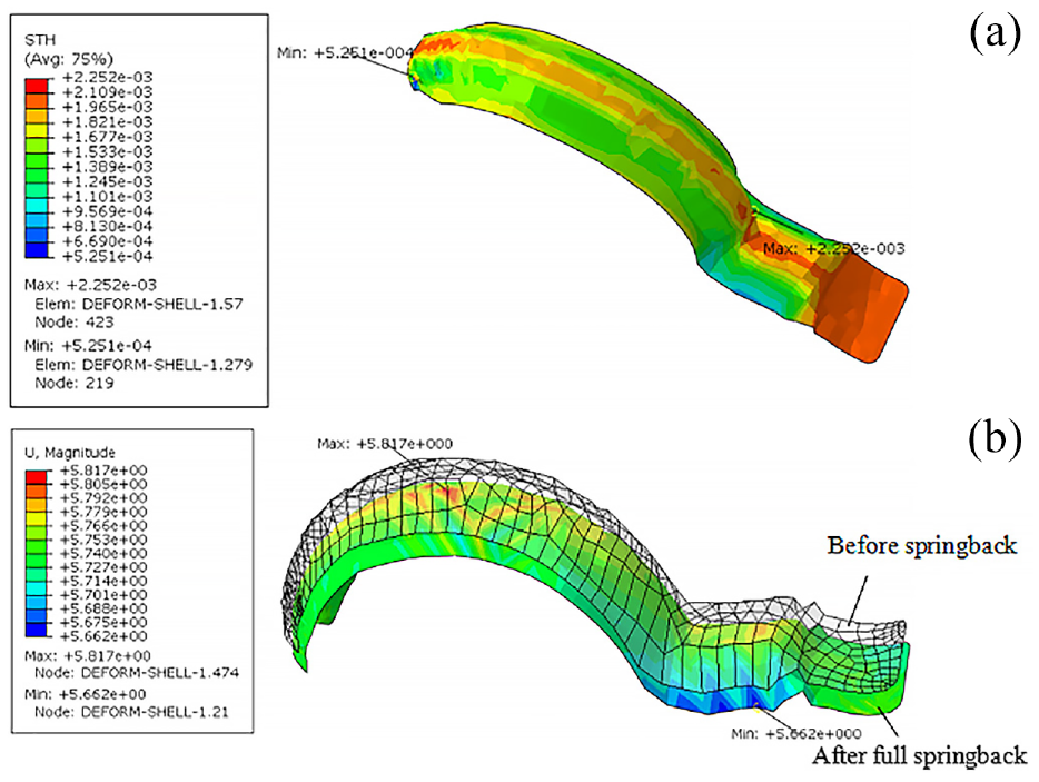
The V-shaped clamp during initial formation: (a) Thickness nephogram and (b) Springback nephogram.
According to preliminary simulation results, the quality of the parts molded using the initially specified process parameters is poor, with a danger of cracking, wrinkling and a large springback, which affects the dimensional accuracy of the clamp and sealing ability.
effects of process variables on molding quality
As shown in Figure 5, when the friction coefficient increases, the maximum thinning rate of the V-shaped clamp first decreases and subsequently increases. The maximum thinning rate of the V-shaped clamp is minimal if the friction coefficient is 0.12. The maximum thickening rate of the V-shaped clamp decreases as the friction coefficient increases. This is due to the fact that the energy consumed during the sheet metal forming process is mostly needed for effective deformation, uneven deformation, internal friction losses caused by internal sliding of sheet metal, and overcoming exterior friction losses between metal sheets and mold. Because of the increase of friction coefficient, the fraction of friction energy consumption in total energy consumption increases, which leads to a drop in the energy consumption ratio for effective and uneven deformation of metal sheets. Therefore, the fluidity of the material is reduced, resulting in a progressive increase in the maximum thinning rate and a gradual decrease in the maximum thickening rate. A smaller coefficient of friction, on the other hand, is not always preferable. As the friction coefficient falls, so does the fraction of friction energy consumption in total energy consumption, whereas the proportion of energy consumption for uneven deformation of metal sheets increases. In consequence, the non-uniformity of metal sheet deformation gradually emerges. If the friction coefficient is excessively low, the thinning and thickening rates of produced components will increase. 19

Maximum thinning and thickening rates, and maximum springback with variations in friction coefficient.
According to Figure 5, the maximum springback of the V-shaped clamp exhibits a rising trend as the friction coefficient rises. The springback is stable while the friction coefficient is between 0.12 and 0.20. The calculation shows how to determine the friction coefficient f using equation (1):

where F stands for friction, N for positive pressure, A for contact area, τ for shear stress, and σs for the metal’s yield limit during plastic deformation. As shear stress rises due to an increase in friction coefficient, the springback of the molded part gradually increases after unloading the stamping mold. When the shear stress τ reaches the shear yield stress k, the slip does not necessarily occur on the interface between the mold and the sheet metal. On the contrary, it can occur on the inside of the sheet metal, while the external interface remains motionless. This phenomenon is the interface adhesion in the forming process. The calculation yields the expression for shear stress τ, which is displayed in equation (2):

where m is the coefficient of friction shear. The value of m is 1 and the shear stress τ is constant during adhesion friction. After the stamping mold is emptied, the springback of the molded part is now steady. With the steady rise of the friction coefficient, the tensile stress at the contact also rises, which is the cause of a further increase in the amount of springback of the produced part after the stamping mold is unloaded.
As demonstrated in Figure 6, the maximum thinning rate of the V-shaped clamp decreases when stamping speed increases, peaking at a maximum thinning rate of the smallest value at a stamping speed of 10.00 mm·s−1. The maximum thickening rate of the V-shaped clamp exhibits an increasing trend with an increase in stamping speed. Nearly all friction work involved in the molding process is turned into heat energy. Equation (3) can be used to express friction work ωf:


Maximum thinning and thickening rates, and maximum springback with variations in stamping speed.
where v is the stamping speed, N represents positive pressure, and f is the friction coefficient. The faster the stamping speed is, the greater the friction work and the heat energy are, which brings the rapid increase of the surface temperature of the sheet metal. Additionally, the high pressure exerted on the metal sheet’s surface results in electron diffusion and atomic combination of the metal in this position, and the phenomena of cold welding between the metal sheet and the mold will occur. The metal sheet will thin or thicken as a result of the cold welding process, because the weaker metal sheet particles at the cold-welding junction will be ripped away from the matrix when the metal sheet and the mold surface slip once more. A portion of the particles are left on the mold’s surface with enough strength to form sticky tumors, and these tumors will scrape the surface of the molded object as well. This is the cause of the maximum thinning rate’s erratic fluctuations, and it also explains why the maximum thickening rate rises as stamping speed increases.
The maximum springback of the V-shaped clamp first drops and subsequently increases with the increase in stamping speed, as shown in Figure 6. The maximum springback of the V-shaped clamp is the minimum when the stamping speed is 10.00 mm·s−1. The hydrodynamic lubrication category includes the lubrication used in metal sheet stamping. Newton’s viscosity law gives the following definition of fluid shear stress τl:

where η is the viscosity coefficient, p is the fluid pressure, z is the dimension along the film thickness direction, h is the gap between the two surfaces, and U0 and Uh respectively represent the velocities of the two solid surfaces. Equation (5) can be found by integrating the shear stress on the surfaces of z = 0 and z = h:
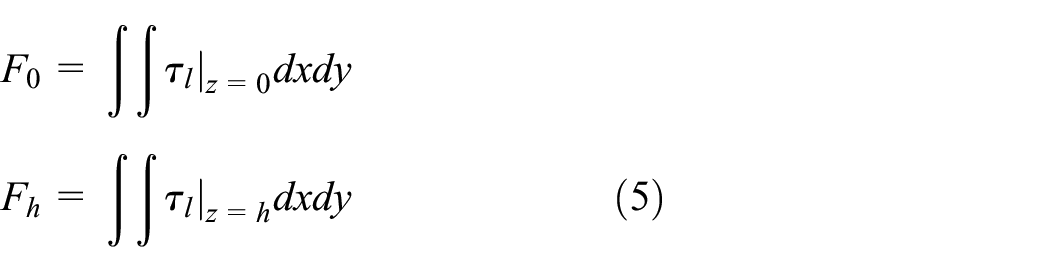
where F0 and Fh are the friction on the surfaces with z = 0 and z = h, respectively. The relative sliding speed of the two surfaces (Uh–U0), which affects the fluid shear stress and friction F0 and Fh, also increases with an increase in stamping speed. As a result, the molded part’s Mises yield stress rises, increasing the molded part’s springback after the mold is unloaded. Because of the reduced friction F0 and Fh caused by the slow stamping speed, metal sheets slide more easily, but it is also more likely to springback. Therefore, there is an ideal stamping speed for molded part springback.
The maximum thinning rate and maximum thickening rate of the V-shaped clamp exhibit a decreasing trend when the mold gap widens, as can be observed in Figure 7. This is due to the fact that when the mold gap widens, the metal sheet’s limitation shrinks, resulting in more uniform thickness distribution and a reduction in the maximum rates of component thinning and thickening. In contrast, Figure 7 demonstrates that the maximum springback of the V-shaped clamp increases as the mold gap widens. This is because the mold gap is large, which is conducive to the sliding of the metal sheet. Moreover, the workpiece is not fully formed, and the Mises stress distribution of the molded part is uneven, which causes the increase of springback after the stamping mold is unloaded.

Maximum thinning and thickening rates, and maximum springback with variations in mold gaps.
The key element influencing the simulation results (which have a wide range) is stamping speed, according to the single-factor rotation simulation findings. The best results for the maximum thinning rate, maximum thickening rate, and maximum springback are obtained when the stamping speed is set to 10.00 mm·s−1. Mold gap and friction coefficient are ancillary parameters that have an impact on the simulation results. The overall outcome is better for the friction coefficient when it is in the range of 0.12 and 0.16. Regarding the mold gap, it has little effect on the maximum rate of thinning and maximum rate of thickening. The mold gap has an impact on maximum springback; the narrower the mold gap, the better. Consequently, the optimum overall result is obtained when the mold gap is adjusted to 2.00 mm.
Analysis of orthogonal experiment findings
The orthogonal experiment results are shown in Table 2.
The orthogonal experiment results.
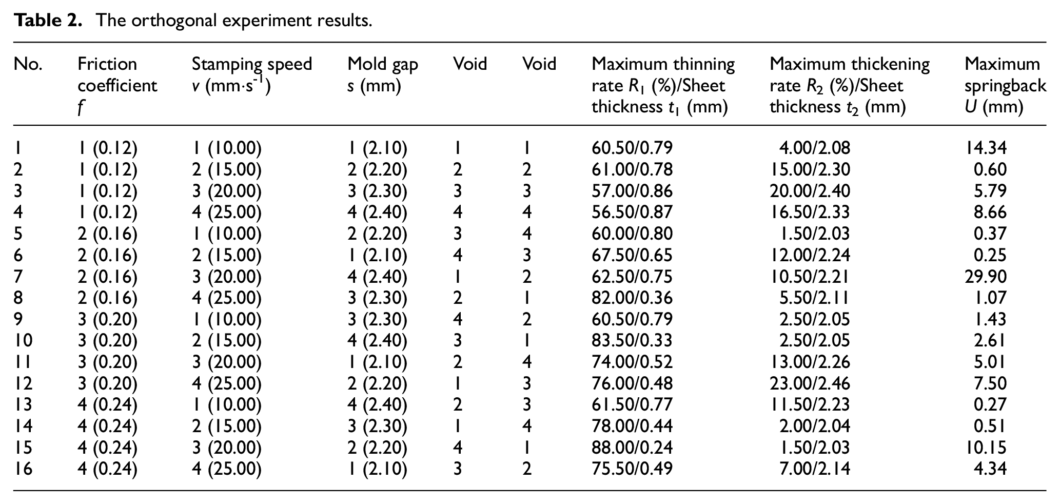
Table 3 displays the comprehensive scoring results of the orthogonal experiment.
The comprehensive scoring results of the orthogonal experiment.

The orthogonal experiment’s outcomes are examined, and the greater the score, the better the outcome. The fifth group receives the greatest overall score, indicating that a friction coefficient of 0.16, a stamping speed set at 10.00 mm·s−1, and a mold gap of 2.20 mm are the ideal stamping process parameters. The V-shaped clamp currently has a maximum rate of 60.00% thinning, a maximum rate of 1.50% thickening, and a maximum springback of 0.37 mm. These results show that the clamp exhibits the best thickness uniformity and springback properties. The single-factor alternate method’s principles are in line with the optimal combination that was produced by using this orthogonal experiment.
Simulation-based comparison of molding quality before and after optimization
Before optimization, the maximum thickening rate is 12.50%, and the maximum thinning rate is 73.50%. After optimization, the maximum thickening rate is reduced by 11.00%. It becomes 1.50%; the maximum thinning rate is reduced by 13.50%–60.00%. It can be concluded that through optimization, the possibility of cracking and wrinkling of V-shaped clamps is significantly reduced.
The key to the formation of the V-shaped clamp, as demonstrated by the simulation above, is the transition zone between the convex boss and the arc surface. Figure 8 shows two paths, with Path 1 traveling the bottom of the transition zone and Path 2 spanning the boss and transition zone’s edges. The study on the forming quality of critical areas is exemplified by these two paths.

Definition of path, comparison of thickness and Mises stress and springback: (a) Path 1 and thickness along path 1, Mises stress and springback before optimization (b) Path 2 and thickness along path 2, Mises stress and springback after optimization.
The maximum thickness of the formed part in this zone is 2.25 mm when the stamping process parameters are not optimized, and the thickness of the metal sheet is noticeably increased. After being optimized, the maximum thickness is 2.03 mm, and the thickening phenomenon is significantly improved. It can be seen that the edges of the boss and transition zone are severely thinned and prone to cracking. Prior to optimization, the minimum metal sheet thickness of the path 2 is 0.83 mm; through optimization, the minimum thickness is 0.88 mm. The risk of cracking has been greatly reduced thanks to optimization, which has improved the uniformity of the metal sheet thickness in this region.
The maximum springback for the formation of a V-shaped clamp is 5.82 mm before optimization and 0.37 mm after optimization. Having being optimized, the maximum springback is reduced by 5.45 mm, and the dimensional accuracy of the molded part is much enhanced. The Mises stress on the molded portion ranged from 52.22 to 659.00 MPa after optimization, whereas it ranged from 82.12 to 659.00 MPa before optimization. The Mises stress is significantly reduced and distributed more uniformly in the area between the convex boss and the arc surface after optimization, as well as in the tail of the V-shaped clamp. This is because the constraining conditions of the metal sheet during the forming process are altered by changes in the stamping process parameters, dispersing the surface stress.20,21 Thus, springback is reduced in the optimized V-shaped clamp.
Based on the aforementioned analysis, the optimization plan’s values for the stamping process parameters encourage the metal sheet’s radial displacement, increase the rate at which the mold cavity is filled and the homogeneity of the formed part, and decrease the likelihood of cracking and wrinkling. On the other hand, it disperses the surface stress of the metal sheet, significantly reduces the Mises stress in key areas and distributes it more evenly on the whole part, makes the amount of the springback become smaller after forming and improves the forming accuracy of the V-shaped clamp.
Experiment-based comparison of molding quality before and after optimization
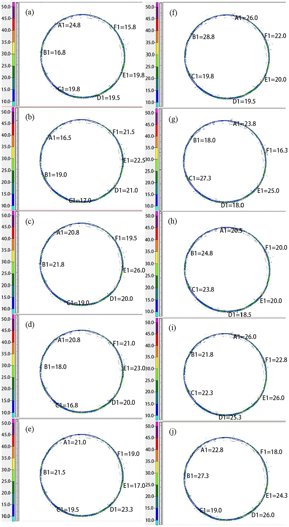
The results of the profile dimensional measurement were recorded, as shown in Figure 9. On the premise that all the formed parts are qualified, the forming dimensional accuracy of the V-shaped clamp was evaluated with the comprehensive scoring method, and the dimensions and scores of 10 samples were noted in Table 4.

Results of profile dimensional measurement: (a)~(e) Cross-sectional dimensions of the V-shaped clamp before optimization, (f)~(j) Cross-sectional dimensions of the V-shaped clamp after optimization.
Cross-sectional dimensions and scores of V-shaped clamps.

Groups (a) to (e) of the V-shaped clamp samples in Table 4 were produced using the initial process parameters, while Groups (f) to (j) were produced using the optimized process parameters. The sample comprehensive scores after improving the process parameters are significantly better than those before optimization based on the cross-sectional dimensions of the molded parts. As a result, the dimensional accuracy of the V-shaped clamp is greatly increased by the adjusted process parameters.
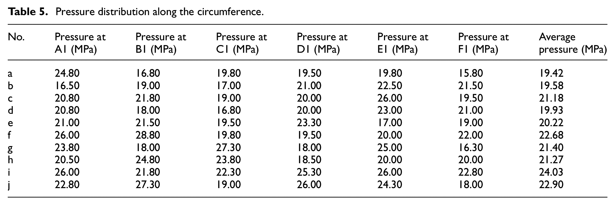
Figure 10 and Table 5 displayed the Fuji paper test results under V-clamp working conditions. The optimized V-shaped clamp exerts more pressure on the nominal flange, implying a stronger axial force and a better operating condition.
Pressure on Fuji paper: (a)~(e) Pressure distribution before optimization, (f)~(j) Pressure distribution after optimization.
Pressure distribution along the circumference.
Although sheet metal stamping technology has reached a fairly advanced stage currently, there is still much room for development in terms of managing the forming defects of intricate parts. Mold gap and stamping speed can be controlled via conventional parameter adjustment. The friction coefficient may be accurately controlled by designers thanks to surface treatment technologies,22–24 and the methods used in this work. Meanwhile, these technologies need further study and discussion.
Conclusions
This article is based on ABAQUS to numerically simulate the stamping forming process of V-shaped clamps, reveal the influence of stamping process parameters on V-shaped clamp stamping forming, and optimize the design of the V-shaped clamp stamping forming process. The results are as follows:
(1) The stamping speed is the main factor affecting the forming quality of V-shaped clamps. When the stamping speed is set at 10.00 mm·s−1, the maximum thinning rate, maximum thickening rate, and maximum springback have the best comprehensive results. When the friction coefficient is between 0.12 and 0.16, the overall result is better. The mold gap has no effect on the maximum thinning rate or maximum thickening rate. The maximum springback is proportional to the mold gap.
(2) The ideal stamping process parameters are as follows: a friction coefficient of 0.16, a stamping speed of 10.00 mm·s−1, and a mold gap of 2.20 mm.
(3) The combination of the aforementioned optimum process parameters significantly improves the dimensional accuracy and mechanical qualities of the V-shaped clamp under working conditions.
Footnotes
Handling Editor: Chenhui Liang
Declaration of conflicting interests
The author(s) declared no potential conflicts of interest with respect to the research, authorship, and/or publication of this article.
Funding
The author(s) disclosed receipt of the following financial support for the research, authorship, and/or publication of this article: This work was supported by the Founding Project in Nanjing Vocational College of Information Technology [grant number YK20221401], the Funding Project for Enterprise Practice Training for Young Teachers in Jiangsu Province’s Higher Vocational Colleges [grant number 2023QYSJ069], the Scientific Research (Starting) Foundation for High-level Talents in Nanjing Vocational College of Information Technology [grant number YB20211403, YB20211404], and the Natural Science Foundation of the Jiangsu Higher Education Institutions [grant number 22KJB480008, 22KJB430034].