
Abstract
In the existing research, polygonal -shaped dies were manufactured based on the dimensions of the design. These dies were then assembled on the deep-drawing device to create polygonal cups (specifically heptagonal cups) for conducting experimental work tests. The process was achieved via a deep-drawing operation to create heptagonal cups with dimensions (diameter D = 40mm and height L = 31.5 mm). For both experimental work and finite element analysis, the cups of heptagonal shapes were formed from flat circular blanks of Low Carbon Steel (thickness to = 0.7 mm) and diameter D = 80mm. A commercial software program, ANSYS, was employed to perform this finite element analysis. The research aims to study the effect of different radial clearance (RC = 1.1to,1.2to, and 1.3to) between die and punch for heptagonal shape DD operations on the forming load, the height of the cup, thickness distribution, strain and stress distribution along the cup wall (side-wall and wall curvature). The analysis outcomes indicate that the maximum forming force was 51.250 kN with the wall curvature, the maximum effective strain was 0.8231, and the maximum stress was 676 MPa when the
Introduction
Deep-Drawing (DD) is one of the processes of Sheet Metal Forming (SMF) employed in considerable industrial fields. By it, a sheet metal blank (B) draws in a typical die of conventional or complex shapes like circular, box, conical, oval, trigonal, octagonal, etc. The process has many apps in kitchen appliances, beverage containers, automobiles, the aerospace industry, etc. The process of DD is highly intricate and is influenced by many factors such as Forming Limit Diagram (FLD), punch and die radius, the radial clearance between the punch & die, lubrication system type, the press velocity, sheet metal features, etc.
1
One of the parameters that plays an important role in the SMF processes is the FLD. the FLD is a crucial tool in SMF processes, providing a graphical representation of a material’s formability. It helps manufacturers assess the limits of plastic deformation without failure, optimize the forming process, and select suitable materials for specific applications. So many researchers conducted multiple studies about FLD; Park et al.2–4 conducted three studies on the Fracture Limit Diagram. The first study developed a unique anisotropic ductile fracture criterion and transformed it into a Fracture Forming Limit Diagram (FFLD) to assess forming severity for high-strength steel sheets. The proposed criterion accurately predicted fracture strain under different stress conditions. The second study presented a solution that models anisotropy and asymmetry-induced distortional yielding behavior in metal sheets. This solution accurately predicted the evolution of the distorted yield surface for different materials and conditions. Lastly, the third study used a decoupled formulation and Lagrangian interpolation function to simulate anisotropic fracture behavior in the automotive industry. This approach accurately represented the fracture behavior of automotive components. Basak and Panda5–7 conducted multiple studies on the FLD. In the initial investigation, focused on predicting the failure strain in two types of SM, namely EDD and AA5052 SM. Among the various yield theories considered, the Yld2000-2d yield theory provided the most accurate description of the experimental limiting strains. Additionally, the MK-FLD and BW-FFLD models demonstrated accurate predictions of the limiting strains in the PEPS locus. Furthermore, the calibrated BW fracture loci effectively estimated the fracture strains in different forming tests. In a subsequent study, accurately estimated and analyzed the forming limit criteria for necking and fracture in the two-stage forming process of anisotropic SM using the Yld2000-2d yield model. observed minimal shifting of the strains during the process. By incorporating the PEPS based failure limits as the damage model in FES, they achieved a max absolute error of 5% and 6% for necking and fracture, respectively, in predicting the dome height. Lastly, in their third study, the researchers examined the failure limits of aluminum AA5052 SM through experiments and fracture models. The utilization of the anisotropic model significantly improved the accuracy of predictions, while the BW model precisely estimated the fracture surface strains. Moreover, the BW model successfully predicted the location of fractures and the dome height in two-stage forming experiments with minimal error. Multiple studies have examined factors affecting DD operations to achieve a flawless end product. Zein et al.
8
studied the effect of die design parameters on SM blank thickness and thinning in the DD process. They validated their findings by comparing FE analysis with experimental results. They also created a model to predict blank thickness and thinning based on die design parameters. FEA can optimize performance parameters without costly funding practices. A study by Reddy et al.
9
analyzed strains on a cylindrical mug made of Aluminum alloy AA6061. The study used a sheet blank with a diameter of 350 mm and a thickness of 0.953 mm. The results showed that by optimizing design parameters, deeper mugs could be produced. The experimental outcomes were consistent with the published EES outcomes. In a study by Krupal Shah et al.,
10
the parameters of DD operation effect were analyzed to identify the causes of imperfections and thinning in products. Statistical and experimental procedures were used to determine the influence of these process parameters. The study found that the force of BH had the greatest impact in the DD process, followed by die radii and punch nose radii. Smaller punch beak radius led to ripping in the mug, while wrinkling in the drawn product was caused by a small force of Arab
11
conducted research paper about the DD operation of circular shape blanks was studied using FEM analysis. The drawability of the circular blank was compared to theoretical and experimental (EXP) values, considering the initial diameter of the blank and DD parameters. The resulting circumferential and radial strains were plotted. The thickness variation of the mug flange was also analyzed using FEA and EXP values, taking work-hardening into account. Saani et al.
12
simulated a single-stage St mug DD process, considering industry specifications. They investigated the effects of parameter deviations, including B-H force, die filet radii, and friction coefficient, on the thickness of the drawn mug, punch load response, and equivalent plastic strain. The study found that die filet radii had significant variation and were fragile, while the force of B-H was the smallest and most delicate parameter. Sener and Kurtaran
13
conducted a study on a rectangular mug manufactured from a stainless steel AISI 304 sheet. The mug underwent analysis using both Finite Element (FE) and Experimental (EXP) methods. Computer modeling was employed to carry out the Finite Element Method (FEM) for the Deep Drawing (DD) operation. The thickness distribution predicted by the Finite Element Analysis (FEA) was compared to the Experimental (EXP) values. The results indicated a reasonable agreement between the FEA and EXP outcomes. It was observed that the minimum thickness occurred at the punch radius in both the Finite Element Analysis (FEA) and Experimental (EXP) approaches. Jawad and Jaafar
14
examined various factors related to the punch in the forming process of a mug. These factors included the profile radius of the punch, the thickness of the mug wall, the amount of spring-back generated after forming, the attachment areas between the punch and the blank, the strain distribution across the mug wall, and the height of the mug in the DD process. The results of their study revealed that the distributions of strain were similar for all punch shapes. Additionally, the corner radii of the punch did not have a significant impact on the drawing load. However, as the profile radii of the punch increased, the thinning of the mug, the height of the formed mug, and the percentage of spring-back quantity all increased. Vedpathak et al.
15
expected the required load for conducting the DD process. The sizes of the punch and die are obtained from theoretical values. The load required to draw the cup, as well as the deformation and faults such as wrinkles and tearing, can be represented by FES. By using this procedure, it is easy to determine the required load in a minimal stage, compared to the traditional trial and error method. This leads to saving time, money, and material wastage. Gharehchahi et al.
16
conducted research on the Finite Element Analysis (FEA) of a cylindrical mug’s DD parameters. The FEA outcomes were compared to experimental testing (EXP) results. The study used the Abaqus Software Program and the Finite Element Method (FEM). Comparing thickness and circumferential strains distribution, as well as radial load distribution, between FEA and experimental outcomes, it was shown that FEA accurately examined the DD operation. Mukhirmesh and Jawad17,18 conducted a study on DD processes of heptagonal shapes, focusing on two types of research. The first research examined the one-stage DD operation, while the second research explored the multi-stage DD operation. Both studies utilized Direct & Indirect Methods, incorporating EXP work and FEA to manufacture intricately shaped mugs (spline) and analyze various process parameters. The findings from both studies indicate that the DD process can successfully produce parts with heptagonal shapes. Additionally, it was concluded that the Indirect (Redrawing) Method is capable of creating a complete heptagonal part with flaws, in comparison to the Direct (Drawing) Method. Kabakçı et al.
19
conducted an experiment on the mechanical formability of Al6061-T6 sheet material using a pre-bulging process. A unique die entrance design was incorporated into traditional DD dies. The study examined the formability of the material and analyzed the impact of the innovative design on energy consumption and thickness distribution. The experiments involved DD dies capable of mechanically pre-bulging at angles of 0°, 15°, and 30°. The results showed that the material could now be deep drawn at a drawing ratio of ß = 2.2 using the new method, compared to ß = 2.0 with the conventional method. The forming force was also reduced by 24.45%. Jawad and Ikal
20
researched the impact of different radial clearances on stress and strain distribution in star-shaped cups made through the DD process was investigated. Three clearances (1.1, 1.2, and 1.3) between the die and punch were used. The findings showed that the highest drawing force, effective stress, effective strain, and wall squeezing in the DD process occurred with a radial clearance of 1.1 t. a study of EXP and FE about the different radial clearance influences on the strain & stress distribution in the star mugs of DD process. Three kinds of different Radial Clearance (1.1, 1.2, & 1.3) between punch & die are employed to examine the effect of RC. The outcomes displayed that the max. of the drawing force, effective stress, effective strain, and a squeeze process of DD with the mug wall emerged when RC (1.1 t) was employed. Luigi
21
introduced a new method for analyzing DD operation control using Punch-Travel. The method considers the blank draw-in at different points and adapts the force of BH as a process parameter. The technique is applied to a T-Shaped part DD process using a St (DC05) blank with a thickness of 0.750 mm. The analysis shows that the size of the blank draw-in is a representative indicator for the quality of the formed part, specifically in terms of thinning and decorative defects. Once the optimal condition and corresponding blank draw-in are determined, the feedback control algorithm can adjust the force of BH accordingly. In a study by Mukhirmesh and Dalfi,
22
the DD operation for creating heptagonal shapes from circular blanks and cylindrical mugs was analyzed. The study compared EXP and FEA results and found that the maximum punch load required for a heptagonal-shaped mug is 40.25 kN, while in the redrawing process, it is 35.16 kN. The maximum effective strain recorded during redrawing for a heptagonal-shaped cup is 0.418. The redrawing operation is a suitable deep-drawing procedure for manufacturing heptagonal parts. Dağtekin et al.
23
developed various techniques to improve the drawing height, including using blanks with precisely machined edges. The edges of the blank material were thinned at specific angles during the examination to minimize negative effects. The study compared these machined blanks to unprocessed ones. The best drawing height was achieved with a 1° machined edge and a blank diameter of 95 mm. Additionally, using the specially manufactured blank in the DD process reduced power consumption by approximately 7%–31% and material weight. Ballikaya et al.
24
studied the impact of the HMDDM method with an angled die surface on sheet metal cups. The study used 0.9 mm thick sheet metal material and examined various parameters. Numerical analysis experiments were conducted using ANSYS 15.0. The Taguchi experiment plan and L18 orthogonal array were used. Statistical analysis was done using ANOVA in MINITAB 17.0. Results showed a maximum thinning effect of 15% and a thickening effect of 10%. Tricarico and Palmieri.
21
studied process control during the punch stroke and proposed a new method. The method uses blank draw-in as the control variable and blank holder force as the adjustable process parameter. The study focused on DD a T-shaped component using a 0.75 mm thick blank made of DC05 steel. Results showed that measuring blank draw-in effectively indicates component quality. An optimal condition and corresponding blank draw-in were determined, and a feedback control algorithm successfully adjusted the blank holder force based on recorded draw-in. Reddy et al.
25
studied metal sheet formability in DD, analyzing the effects of different sheets and die/blank holder angles. Specifically, 0.8 mm SS304 and Brass sheets, along with a 0.9 mm Aluminum sheet, were examined. DD tools were created and utilized, and numerical simulations were performed on cylindrical cups with different variables. The evaluation of punch forces and dome heights revealed the correlation between metal sheet formability and tool geometries. Brass sheets exhibited higher strain formation, while aluminum sheets experienced higher stress. Vallaster et al.
26
analyzed the impact of strain rate dependent material modeling on simulating SMF. They performed tests on steel HC340LA at different strain rates and used the data to create a material card for numerical simulations. Experiments were conducted to validate the model, comparing results with force-displacement curves and part geometry. Numerical investigations were also done to study the influence of draw bead height and blank holder force on strain rate distribution and process force. The objective of this research study is to develop and examine the heptagonal shape (heptagonal) in comparison to other research studies that utilize single-stage DD operations using EXP and FEA. Additionally, the EXP and FEA results will be compared for the load of punch, thickness, effective strain, and effective stress distribution under different Radial Clearance (
Experimental procedure
The sheet metal blank utilized
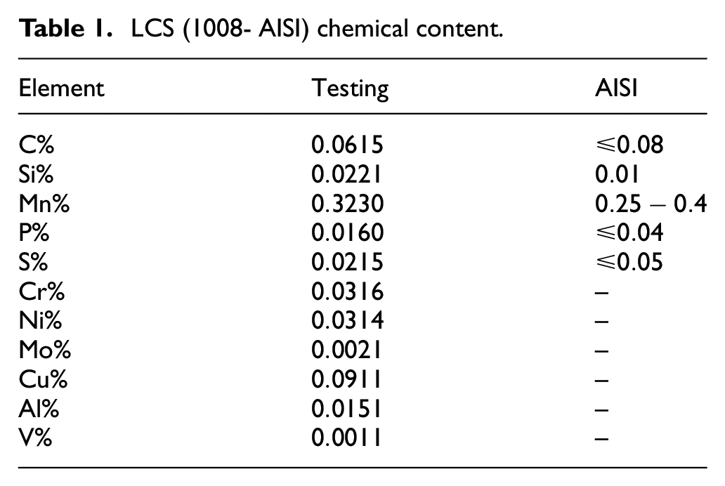
In this research work-study, the sheet metal blank utilized is Low Carbon Steel (LCS) (1008-AISI). It is selected because of its specification, more heightened ductility, and due to excessive utilization in several industrial fields. Chemical analysis was applied at (State Company for Engineering Rehabilitation and Testing) to inspect and verify the chemical content of LCS and confirm the manufacturing credential of its (Table 1).
LCS (1008- AISI) chemical content.
The mechanical characteristics of the employed sheet metal blank play a crucial role in the deep-drawing (DD) operation. In order to specify the mechanical characteristics of the LCS (1008-AISI) and obtain more precise FEA results, trusting on the ASTM E8M, 27 three tensile test experimental samples are created from the LCS (1008-AISI) sheet metal. These samples are cut using a wire-cutting machine (WCM) in three different rolling directions (RD) (RD = 0°, 45°, and 90°). The test samples are then experimentally tested using an adaptable testing machine to determine the mechanical characteristics of the LCS (1008-AISI) (Figure 1), as shown in Table 2.
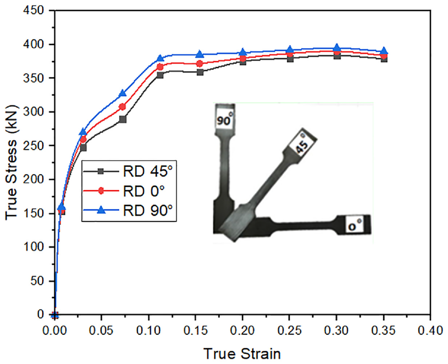
True stress-strain curves for tensile samples taken from LCS (1008-AISI) sheet metal.
Mechanical properties of LCS (1008-AISI) sheet metal.

Experimental tests
To carry out the experimental work, the dies for the DD process were fabricated according to their design sizes from structural steel due to their high strength and hardness by CNC machine and WCM. After the machining process, a heat treatment process was performed on the dies of DD to increase their hardness. Then, the test device type


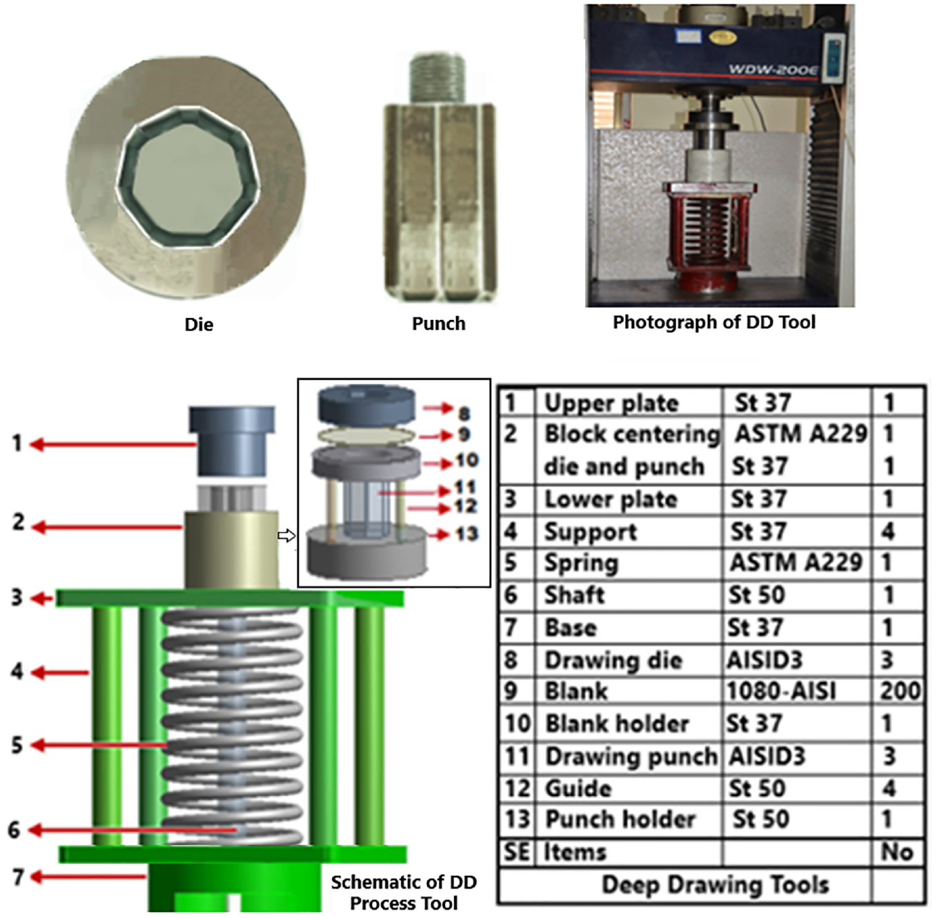
The tools and dies of heptagonal shapes DD operation.

The cup of heptagonal shape DD operation.

The square grid (a) before the DD operation, and (b) after the DD operation.
Finite Element Analysis (FEA)
Finite Element Analysis (FEA) is now widely employed and has created a lucrative industry worth billion. It effortlessly solves complex stress-related problems and is considered indispensable. The FEM is a numerical technique for analyzing stresses and deformations in structures. It involves dividing the structure into smaller elements connected by nodes. Accuracy depends on the type, arrangement, and number of elements. A finite element model is constructed, with material properties, loading conditions, and boundary conditions specified. Engineering software packages are available to model and simulate structures, providing insights into their behavior.
28
In this FE study of the DD process of the polygonal cup with seven edges, the software program ANSYS (Workbench) (von-mises) was employed to perform the FEA and to model and analyze the DD process of the heptagonal cup (D = 40 mm, and L = 31.5 mm) made from an acicular shape blank of LCS (1008-AISI) with dimensions (DB = 80 mm and t = 0.7 mm). In this analysis, the used metal is LCS, so it is added to the engineering data of the static structure and set with the materials with its characteristics, as shown in Table 2. All dies of DD processes are designed related to the size of die dimensions and analyzed in the system analysis static structure of the workbench software. The set die tools of DD; the circular shape blank (B) is a flexible and pointed LCS as a material, while the remaining tools of DD; Die (D), Punch (P), and Blank-Holding (BH) are rigid and made from structural steel. The set contact dies areas; In this DD process, there are three contact friction areas. The first contact area is the upper face of the B (as a contact part) in contact with the lower face of the BH (as a target part). The second contact area is the upper face of the B (as a contact part) in contact with the face of the P head and the faces of the side wall of the P (as a target part). The third contact area is the bottom face of the B (as a contact part) in contact with the top face of the D and the side wall faces of the D cavity (as a target part). The Coeff. of friction between interface B & P

(a) Die tools of heptagonal shape DD and (b) cup of heptagonal shape DD (FEA).
Results and discussion
This research arrangement with EXP and FE was employed to produce heptagonal cups of DD operation from the flat circular blanks of LCS, as depicted in Figure 6.
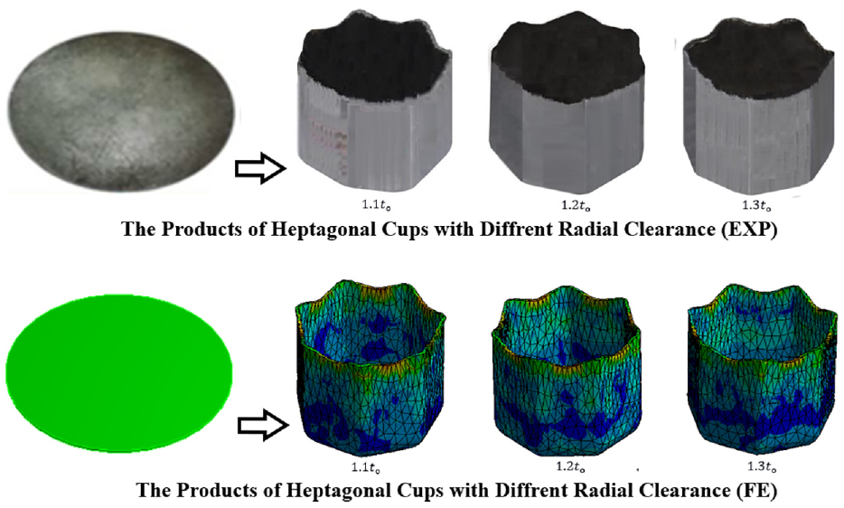
Heptagonal shape DD operations for EXP & FEA.
The outcomes of both EXP & FE of DD process heptagonal shape were registered, estimated, and then plotted in multiple Figures to discuss, analyze, and compare to study the radial clearance effect on the heptagonal cup wall along the sidewall and wall curvature.
I. Deep Drawing Force: For both EXP & FE, Figure 7 describes the graph between punch load and punch travel of the DD process of heptagonal shape under the effect of various
II. Thickness & Thickness Strain Distribution: For both EXP & FEA, Figures 8 and 9 reveal the thickness and thickness strain distribution along the heptagonal cup wall (side & curvature) under the effect of various
III. Effective Strain: For both EXP & FEA, Figure 10 displays the effective strain along the sidewall of the wall curvature of the heptagonal cup under the effect of various
IV. Effective Stress: For FEA, Figure 11 shows the effective stress along the sidewall and the wall curvature of the heptagonal cup under the effect of various
V. Figure 12 represents the radial clearance

The diagram shows the relationship between the loads of punch and the displacement of punch of heptagonal shape DD.
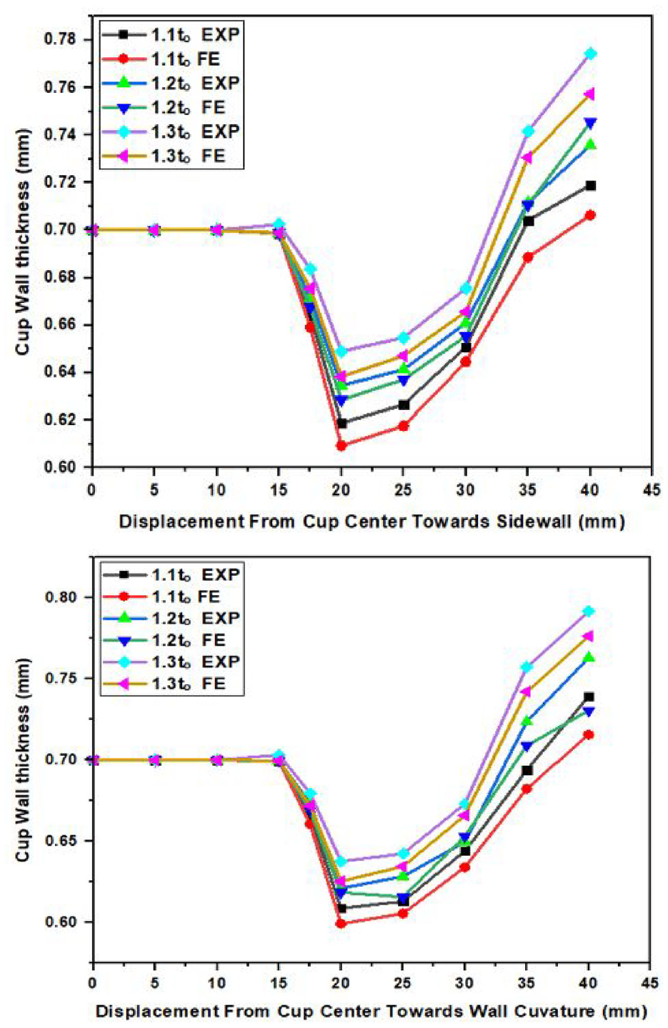
The thickness distribution under various radial clearances along the cup wall (sidewall and wall curvature).

The thickness strain distribution under various radial clearances along the cup wall (sidewall and wall curvature).

The effective strain distribution under various radial clearances along the cup wall (sidewall and wall curvature).
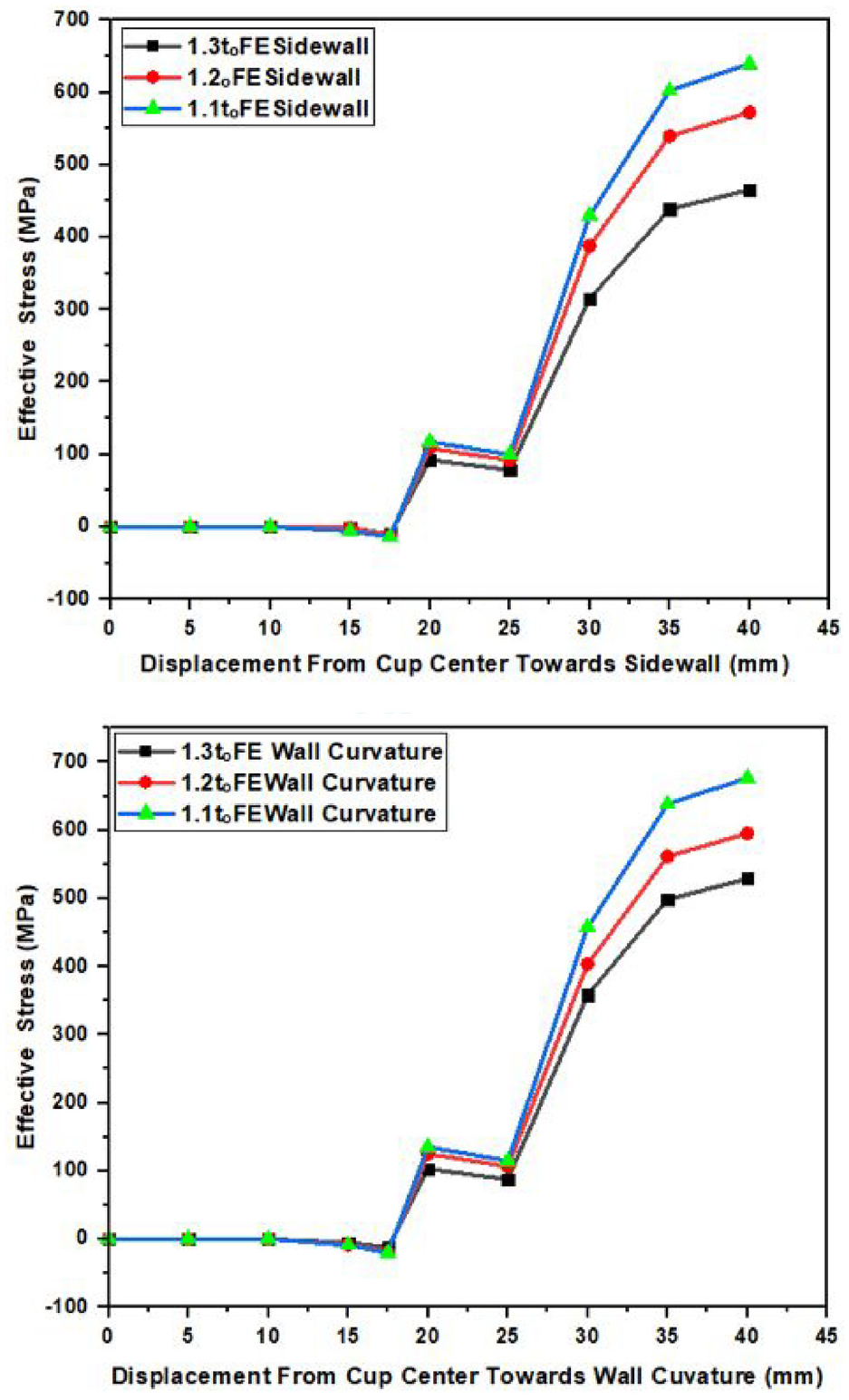
The effective stress distribution under various radial clearances along the cup wall (sidewall and wall curvature).

The radial clearance effect on the height of the cup height by FEA and EXP.
Conclusion
This study aimed to investigate the effects of different radial clearances (1.1to, 1.2to, and 1.3to) on heptagonal deep-drawing operations. The main objective was to understand how these clearances impact forming force, strain, stress, and the occurrence of squeezing in the cup wall. In conclusion, the findings of this research emphasize the importance of carefully selecting the appropriate radial clearance for heptagonal deep-drawing operations. A radial clearance of 1.1to was found to result in maximum forming force, strain, and stress, as well as the occurrence of squeezing in the cup wall. These insights can be valuable for manufacturers and engineers involved in deep-drawing processes, as they provide guidance on optimizing the design and parameters to achieve desired outcomes and minimize potential issues.
Footnotes
Acknowledgements
The authors extend their thanks and appreciation to the team of Materials Strength Lab, Production Engineering Department, University of Technology, Baghdad, Iraq for assisting in conducting experiments related to this research study.
Handling Editor: Chenhui Liang
Declaration of conflicting interests
The author(s) declared no potential conflicts of interest with respect to the research, authorship, and/or publication of this article.
Funding
The author(s) received no financial support for the research, authorship, and/or publication of this article.