
Abstract
During the drilling process of carbon fiber reinforced polymer (CFRP), defects such as exit delamination, tearing, and burrs are prone to occur, among which excessive axial force during drilling is the main reason for the generation of exit delamination defects. In this study, ultrasonic-assisted and conventional drilling with twist and dagger drills were investigated on 5 mm-thick multi-directional laminated fiber sheets made of T300-12k/AG80 carbon fiber composite with different orientations. The axial force evolutions in each case were monitored when drilling holes in CFRP plates, and the axial force of drilling and the appearance characteristics of hole outlet were compared. The experimental results showed that the ultrasonic assisted drilling reduced the axial drilling forces of twist and dagger drill by up to 20.6% and 30.7%, respectively, compared to conventional drills. In addition, as the feed rate increases, the axial force of drilling gradually increases, and the exit delamination factor shows an overall increasing trend. The ultrasonic vibrations reduced the exit delamination damage of both drills. A special structure of the dagger drill effectively avoided exit delamination during ultrasonic-assisted drilling, which makes the incision more neat to improve the processing quality.
Keywords
Introduction
Carbon fiber reinforced polymer (CFRP) composites are widely used in many cutting-edge technology fields due to their high specific strength, specific modulus, corrosion resistance, and fatigue resistance.1–3 For example, in China, CFRP composites are extensively used in major projects such as large aircraft, space launch vehicles, and new weapons and equipment. Meanwhile, Boeing’s B787 large aircraft produced in the United States has fully applied composite materials to major load-bearing components, marking the official entry of large civilian aircraft into the era of composite materials.4–6
Due to the high strength, high hardness, and low interlayer bonding strength of carbon fiber composite material, the burr, delamination, and tearing phenomenon appear at the hole outlet during the drilling process, affecting the processing quality.7–10
To address the various machining quality issues associated with CFRP materials during drilling, researchers from both domestic and international sources have conducted studies from multiple aspects, such as optimization of drilling parameters, matching of tool structures, and hole-making methods. Many studies have shown that the hole quality can be improved under conditions of high rotational speed and low feed rate.11–16 However, excessively high drilling speeds can result in rapid tool wear and burn marks on the hole wall. 17 Other researchers have focused on tooling and machining methods. For example, Fernandes et al. 18 reported that gun drills combined the advantages of low axial force, sharp cutting edges, and fast chip evacuation, which allowed them to quickly cut through fibers and reduce tearing and burrs at the entry and exit of the holes. Liu et al. 19 obtained the variation patterns of axial drilling forces with feed rate, rotational speed, and drill diameter through orthogonal and single-factor experiments.
Marques et al. 20 conducted experimental comparisons of different types of tools in the hole-making process, including drilling forces and resulting hole defects. The study found that step drills can significantly reduce drilling forces. Lazar et al. 21 investigated the drilling of CFRP using dagger drills, eight-face drills, and ordinary double-sided drills. They found that the drill point geometry significantly influences drilling forces and torque, and eight-face drills showed the lowest drilling forces and torque. In contrast, ordinary double-sided drills showed the highest. Piquet et al. 22 conducted machining experiments on CFRP using standard twist drills and special drill heads. The results showed that the maximum damage radius generated during drilling with the special drill head was smaller, making it more suitable for CFRP machining.
Ultrasonic vibration-assisted cutting of CFRP can effectively reduce the maximum cutting force, which is of great significance for reducing the cutting temperature, minimizing delamination and tearing defects, improving surface quality, and prolonging tool life.23–25 Shao et al. 26 conducted a study on ultrasonic vibration assisted twist drill in drilling CFRP/Ti materials and found a significant improvement in hole diameter accuracy and hole surface quality. In addition, tool wear conditions in UAD were also significantly alleviated. Li et al. 27 conducted experiments on titanium alloy by using rotary ultrasonic-assisted drilling (RUAD) with a new blade-type tool (eight-face drill), which significantly reduced drilling force, cutting temperature, and burr height compared to conventional drilling (CD). Sun et al. 28 used three different drill bits to drill CFRP, and the experimental results showed that the dagger drill was the best choice. By applying ultrasonic vibration, its axial force and surface roughness were significantly reduced. Cong et al. 29 studied the suitable range of processing parameters for dry ultrasonic-assisted machining of CFRP and demonstrated the feasibility of cold air cooling. Feng et al. 30 found that ultrasonic-assisted vibration drilling can realize the separation of tool and chip, and compared with conventional drilling, the tearing factor at hole exit with ultrasonic-assisted twist drill was lower. Through experiments, Li et al. 31 proved that brittle fracture was the main material removal mechanism in CFRP grinding, and ultrasonic-assisted grinding had a number of advantages. Sun et al. 32 found that ultrasonic vibration assisted milling of CFRP has more significant advantages in cutting force and cutting temperature, and surface defects are significantly suppressed. The surface roughness is also reduced, making it an efficient and low-damage machining method/strategy. Liu et al. 33 studied the cutting performance and surface integrity of chromium nickel iron alloy 718 using a ball end milling cutter through rotary ultrasonic elliptical milling. The experimental results showed that the cutting force was reduced by 31.33% under RUEM, and the tool side wear was significantly improved. Gu et al. 34 compiled a large number of articles on the influence of tool motion trajectory on surface quality formation in ultrasonic vibration machining. They classified ultrasonic vibration machining based on the form of tool motion trajectory, explored the influence of different processing parameters on tool motion trajectory, summarized the research on tool motion trajectory in ultrasonic vibration machining, and looked forward to future research.
Although some researchers have conducted studies on drilling CFRP, there are few studies on the ultrasonic-assisted dagger drilling. Therefore, in this study, twist and dagger drills were used to conduct hole-making experiments on CFRP on a computerized numerical control milling machine and an ultrasonic device for ultrasonic vibration-assisted cutting and conventional cutting. The axial force evolutions during conventional and ultrasonic-assisted drilling with these tools were studied. A comparison was made between the axial force and exit morphology during drilling, revealing the mechanism of tool-induced defect suppression under ultrasonic vibration.
Analysis of ultrasonic assisted drilling motion
Both Twist drills and dagger drills belong to drilling tools, which rely on the cross edge to drill into the workpiece, the cutting edge to cut the material, and the spiral groove to discharge the chips. The twist drills are most widely used in hole processing. Here, the twist drill is used to illustrate the motion characteristics of ultrasonic assisted drilling. As shown in Figure 1, the axial motion of the twist drill consists of the feed motion and ultrasonic vibration. θ is the twist drill rotation angle; n is the rotational speed of the cutting edge at a certain point c; fz is the feed amount of the twist drill; and Vf is the feed speed. f is the ultrasonic frequency and A is amplitude.

Schematic diagram of ultrasonic assisted drilling.
For conventional drilling (CD), the axial displacement Zc and rotation angle θ at point c of the main cutting edge of a twist drill can be expressed as:


Due to the effect of ultrasonic vibration, the twist drill axial displacement superimposed on the ultrasonic vibration in the ultrasonic-assisted drilling (UAD) process can be expressed as:

Assuming that the distance from point c on the main cutting edge of the twist drill to the center of the circle is ρ, the coordinates of the ultrasound-assisted drilling CFRP at a given moment can be expressed as:

If A = 0, equation (4) is the equation for the coordinates of point c on the main cutting edge for normal drilling of CFRP.
The standard twist drill has two main cutting edges (a-edge and b-edge), the phase difference between two points at the same radius of the two main cutting edges is π, and the axial displacement equations of its two edges can be expressed as:

The parameters are set as twist drill radius R is 4 mm, spindle speed n is 2000 r/min, feed fz is 0.02 mm/r, amplitude A is 5 μm, frequency f is 20 kHz, and the cutting trajectory diagram of the cutting edge in conventional drilling and ultrasonic-assisted drilling is plotted using MATLAB software, as shown in Figure 2.

Trajectory diagram of the cutting edge.
The conventional drilling (dotted line) and ultrasonic-assisted drilling (solid line) for twist drill main cutting edge are shown in Figure 2. The main cutting edge trajectory for conventional drilling is continuous and the trajectory spacing is equal due to the cutting thickness is equal, while the two main cutting edge trajectories for ultrasonic-assisted drilling of between the spacing is not equal, but shows a periodic change. The cutting edge and the workpiece experience a process of contact-impact-separation periodically for ultrasonic assisted drilling so that the continuous cutting movement of conventional drilling turn into intermittent cutting to reduce the cutting time to reduce the wear of the cutting edge. The instantaneous cutting thickness of the main cutting edge of the twist drill changes periodically with the rotation of the tool, reflecting the ultrasonic-assisted drilling with variable cutting thickness characteristics.
In addition, the cutting speed of the main cutting edge at point c in conventional drilling is synthesized by the circumferential speed Vr and the axial feed speed Vf at that point c. When ultrasonic vibration is applied in the axial direction, there is an ultrasonic vibration speed Vu in the axial direction in addition to the feed speed, and the cutting speed of the main cutting edge and the transverse cutting edge are also changed accordingly.
Derivation of equation (3) yields the axial feed rate for ultrasonic assisted drilling:

The circumferential velocity at a point on the main cutting edge of a tool during ultrasound-assisted drilling:

The closing speed of the main cutting edge during ultrasonic-assisted drilling at any instant of time:

The spindle speed n is set to 2000 r/min, and the feed fz is set to 0.02 mm/r. The ultrasonic frequency f is set to 20 KHz, and the ultrasonic amplitude A is set to 5 μm. MATLAB software is used to draw the cutting speed graphs of the cutting edges in conventional drilling and ultrasonic-assisted drilling, and to compare and analyze the trend of the cutting speeds V of the main cutting edges and the traversing edges of the twist drills.
The twist drill is mainly composed of a chisel edge and a main cutting edge. The chisel edge is located in the center of the bit, while the main cutting edge is located on the periphery of the bit, as shown in Figure 3. According to Formula 7, the cutting speed is positively related to the diameter of the bit, so the speed of the chisel edge is lower, which mainly plays the role of guidance and stability, while the speed of the main cutting edge is relatively high, which is responsible for the main cutting. Moreover, the chisel edge increases the axial force by scraping and extruding the materials. Therefore, if the axial force is too large, it may cause exit delamination defects when processing the carbon fiber composite material.

Speed of the cutting edge in conventional drilling.
As shown in Figure 4 for the speed change trend of the cutting edge after applying ultrasonic vibration to the twist drill, the cutting speed is also increased with the excess of the cross edge to the main cutting edge (C→D). Compared with the cutting speed of conventional drilling, the cutting speed of ultrasonic-assisted drilling shows a periodic change, which in turn makes the cutting edge and the workpiece contact and separation. It realizes the intermittent pulse cutting mode between the tool and the workpiece, and fundamentally changing its cutting performance.35–36 The periodic change of cutting speed also greatly improves the instantaneous cutting speed of the cutting edge, especially the transverse edge. It changes from pure scraping, extrusion excision of the material into the impact mode of cutting at a certain cutting speed, so that the transverse edge impact CFRP constantly. This mode improve the cutting conditions of the transverse edge and near the cutting edge to improve its sharpness.28,37 The overall reduction of cutting force can effectively reduce the delamination defects.

Speed of the cutting edge in ultrasonic-assisted drilling.
Carbon fiber reinforced polymer (CFRP) drilling experiment
Test tools and plate material
The test tools used in the experiment were a twist and a dagger drill bits, as shown in Table. 1, respectively. Both types of tools were provided by the Shanghai Tool Factory, China. The material of both tools was a hard alloy with a TiAlN coating with a diameter of 8 mm. The twist drill bit had a point angle of 140° and a helix angle of 30°.The structure comparison of dagger drill and Twists drill is shown in Figure 5.
Specific parameters of the drill bits.


Structure comparison diagram of dagger drill and Twists drill.
The test specimens used in this experiment were 5 mm-thick multi-directional laminated fiber sheets made of T300-12k/AG80, with specific parameters listed in Table 2.
Performance parameters of the fiberboard.

Experimental platform and experimental procedure
The ultrasonic vibration system is mainly composed of two parts: ultrasonic generator and ultrasonic toolholder. The ultrasonic generator provides energy for ultrasonic toolholder and the function of the ultrasonic toolholder is to convert the high-frequency oscillation electrical energy to vibration mechanical energy, so that the tool can do high-frequency and large amplitude vibration for processing. The ultrasonic toolholder is made of the transmitting coil, the receiving coil, the transducer, the horn, and the tool, as shown in Figure 6. The transmitting coil and the receiving coil form a wireless transmission system.

Ultrasonic vibration equipment.
The ultrasonic vibration system used in this experiment consisted of an ultrasonic transducer and a longitudinal-torsional amplitude bar, combined with a VMC-850E vertical machining center and a KISTLER 9257B three-component dynamometer with a NI9025 data acquisition card for UAD experiments. The energy transmission of the ultrasonic vibration system was noncontact wireless, and normal drilling was achieved by turning off the ultrasonic power. The overall drilling setup is shown in Figure 7.

Drilling test equipment.
A KEYENCE LK-G5000 noncontact laser measurement system from Japan was used to measure the amplitudes of the twist and dagger drills. This system mainly consisted of an LK-G5000 series laser controller unit, a laser sensor head, LK-Navigator 2 operation software, and a PC terminal. The measurement method is shown in Figure 8.

Vibration of drill bits measurement equipment.
This experiment was mainly aimed at comparing the axial drilling forces and exit surface morphology of twist drills and dagger drills during conventional drilling (CD) and ultrasonic-assisted drilling (UAD) of CFRP, as well as their influence on the drilled hole quality. According to the relevant literature, feed rate has a greater impact on hole quality than spindle speed. Four different feed rates were selected as experimental processing parameters to ensure comprehensive testing, as listed in Table 3.
Processing parameters.

Results and discussion
Analysis of axial force variation with time
Analysis of the axial drilling forces of twist drills over time
The changes in the axial drilling forces in the twist and dagger drills under study, at a feed rate of 75 mm/min and a spindle speed of 3000 r/min were analyzed, as shown in Figure 9. The characteristics of the unfiltered axial drilling force signals of twist drills during CD and UAD of CFRP were monitored over time. In the process of drilling CFRP, the cutting forces in the X and Y directions of the vertical axial force were relatively small and could be neglected.

Axial force evolution of the twist drill.
From Figure 9, it can be observed that the waveforms of drilling forces for conventional drilling and UAD were essentially the same.
Segment A-B: The axial drilling force rapidly increased as the helical edge of the twist drill get into contact with the material, reaching its maximum as the entire main cutting edge penetrated. It can be seen from the graph that the slope of the UAD axial force curve was smaller than that of the conventional drilling axial force curve.
Segment B-C: In this stage, the main cutting edge was fully immersed in the material, representing the stable stage of the drilling process. It can be observed from the graph that the axial drilling force for UAD was smaller than that of conventional drilling. Due to the upward helix angle of the twist drill, the axial force tended to decrease. The average value of the force during this stage was taken as the axial drilling force.
Segment C-D: As the twist drill exited the material, the axial drilling force rapidly dropped until it reached zero.
Analysis of axial drilling forces of dagger drills over time
The processing method of the axial drilling force for dagger drills was the same as that of twist drills. The trend of the axial drilling force for dagger drills can be divided into five stages over time, as shown in Figure 10.

Curve of the axial force of the dagger drill with time.
Segment A-B: When the flutes of the dagger drill first came into contact with the CFRP material and compressed the workpiece, the UAD axial force increased rapidly from 0 to 9 N, while that of conventional drilling (CD) reached 15 N. Then, the first main cutting edge started cutting the material, and the axial force increased rapidly to its maximum, indicating that the first main cutting edge has completely penetrated the material.
Segment B-C: The second main cutting edge started to participate in cutting, entering the hole enlargement stage. The axial force became relatively stable as the rake angle of the second main cutting edge was much smaller than that of the first cutting edge, resulting in a smaller cutting force. At this stage, the axial force of drilling was mainly influenced by the first main cutting edge. The average value of the axial force in the segment B-C was taken as the axial drilling force under this processing parameter for the gun drill.
Segment C-D: When the dagger drill reached the bottom layer of the CFRP material with the flutes, the bottom layer fibers’ strength was insufficient to resist the axial force, resulting in an increased deformation. As the first main cutting edge drilled out, the raised area expanded outward, increasing the delamination zone. Point C was the transition point where the first main cutting edge started to drill out of the material, and at this point, the axial force also decreased rapidly.
Segment D-E: At the point D, the first main cutting edge has been completely drilled out, and the second main cutting edge started executing hole enlargement, so the axial force of drilling slightly decreased. But there was an abrupt change in the axial force near point “E,” mainly caused by flutter due to uneven transition between the second main cutting edge and the reaming edge during the drilling.
Segment E-F: The axial force of drilling continued to decrease slowly. At this stage, both hole enlargement and reaming occurred simultaneously. As the second main cutting edge drilled out, the axial force dropped to zero. After point F, it entered the stage of complete reaming holes, and the hole wall and exit were further refined until the drilling was completed.
Comparative analysis of axial forces in CD and UAD
Since each cutting tool was subjected to eight repeated experiments at each machining parameter, the average value of the axial force was calculated from the eight experimental results. As shown in Figures 11 and 12, the axial forces of both types of cutting tools increased with feed rate. This was because as the feed rate increased, the volume of material removed by the drill bit increased with each revolution. The resistance that the cutting edge had to overcome to cut the fibers also increased, resulting in a significant increase in axial force. However, the increase in axial force for the twist drill became slower at feed rates Vf exceeding 75 mm/min, mainly because the twist drill had a helical structure, and the upward helical force also increased with the feed rate.

Comparison of axial force between conventional and ultrasonic drilling of twist drill.
Comparison of axial force between conventional and ultrasonic drilling of dagger drill.
It can be seen from the Figures 11 and 12 that the axial force of ultrasonic-assisted drilling of both tools is smaller than that of conventional drilling, and the axial force reduction of dagger drilling is the most obvious, ranging from 23.3% to 30.7%, and that of twist drilling is from 16.5% to 20.6%. This is due to the ultrasonic vibration changes the mode of action between the drill and the workpiece, from continuous cutting to intermittent cutting, slowing down the wear of the tool. While the carbon fiber belongs to the hard and brittle materials, the vibration of the high frequency makes impact force of the cross cutting edge and the main cutting edge more stronger, improving its cutting ability. Therefore, the axial force of ultrasonic-assisted drilling is lower than that of conventional drilling.
From the fluctuation range of the error bars, it can be observed that for CD and UAD modes with the two types of tools, the size of the error bars increased with the drilling speed. This was mainly due to increased drilling axial force with drilling speed. The reduced rigidity of the tool led to instability during drilling. When comparing the error bars of the two types of tools, it can be found that the fluctuation range of the axial drilling force for the twist drill was much smaller than that of the dagger drill, indicating that the twist drill was more stable and had smaller force fluctuations during drilling.
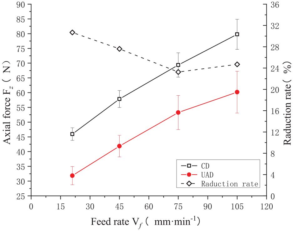
From the comparison of the reduction rate curves of the axial force for the twist drill and the gun drill in Figures 11 and 12, it can be seen that the reduction rate of axial force for the twist drill showed a slight decrease with feed rate, while that of the dagger drill initially decreased and then slightly increased. At a feed rate Vf = 75 mm/min, the latter’s reduction rate reached a minimum of 23.3%, but it still exceeded the maximum reduction rate of the twist drill. Therefore, the dagger drill was more suitable for UAD of carbon fiber composites.
Comparison and analysis of the axial force between the twist drill and dagger drill
As shown in Figure 13, the average values of axial force in the stabilization stage of conventional and ultrasonic-assisted drilling were taken respectively. The axial force of drilling of the two types of tools showed an increasing trend with the increase of the feed rate. By comparing the drilling axial force of the two tools, it is found that under four different feed parameters, no matter it is conventional drilling or ultrasonic drilling, the drilling axial force of dagger drill is smaller than that of twist drill. Especially when the feed speed Vf = 75 mm/min, the axial force of dagger drill is reduced by 22.4 and 23.4 N under conventional and ultrasonic-assisted drilling, respectively. This is mainly because that the special structure of the double apex angle makes the cutting thickness of the second main cutting edge decrease during the drilling process, and the corresponding axial force decreases. Therefore, the dagger drill is more suitable for drilling carbon fiber composites.
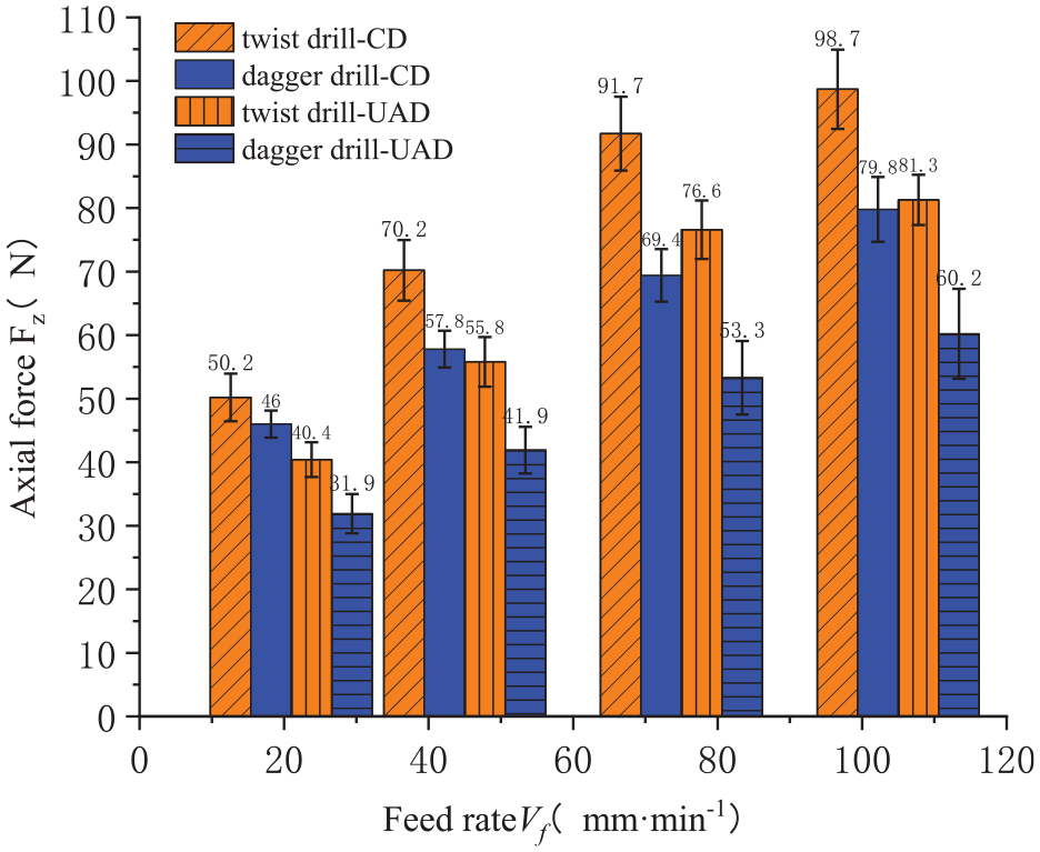
Comparison of axial force between conventional and ultrasonic drilling of two tools.
From Figure 13, it can be observed that the axial force of the twist drill during UAD was not significantly different from that of the dagger drill during conventional drilling. However, when the dagger drill was combined with ultrasonic vibration, its axial force during drilling was much smaller that of the twist drill during conventional drilling. It was the smallest among the four drilling conditions. Since the dagger drill combined drilling, enlarging, and reaming in one tool, the cutting thickness during drilling was small, resulting in relatively small axial forces at each drilling stage. Therefore, the overall axial force during drilling was small. As the axial force was the main cause of exit delamination, the exit delamination damage caused by the dagger drill was lower than that caused by the twist drill. When ultrasonic vibration was applied, the dagger drill’s first and second main cutting edges obtained a higher impact velocity, which was beneficial for cutting off the fiber bundles, resulting in a higher-quality exit morphology.
Analysis of exit morphology in CD and UAD with two types of tools
Defects in carbon fiber composite material drilling mainly occur at the exit end. The main reason is that the outermost few layers of fibers at the exit end are subjected to low binding force from the matrix and have low load-bearing capacity. If the axial force during drilling is too large, it can cause cutting stresses to exceed the material’s ultimate strength, resulting in exit delamination, splitting, and other defects. When the tool’s cutting edge becomes dull, burrs and other defects are easily generated. Among these defects, exit delamination has the greatest impact on the assembly of carbon fiber composite material plates. According to incomplete statistics, more than 60% of the nonconforming rate in aircraft assembly is caused by exit delamination defects during CFRP drilling. Therefore, exit delamination defects are the main focus of analysis.38,39
Currently, the evaluation of exit delamination defects is usually expressed using the area ratio method in Figure 14. Amax represents the maximum area of exit delamination damage (expressed as the area of a circle with a diameter of Dmax), and Anom represents the nominal area of the hole (expressed as the area of a circle with a diameter of Dnom). The delamination factor is calculated as the ratio of Amax to Anom.

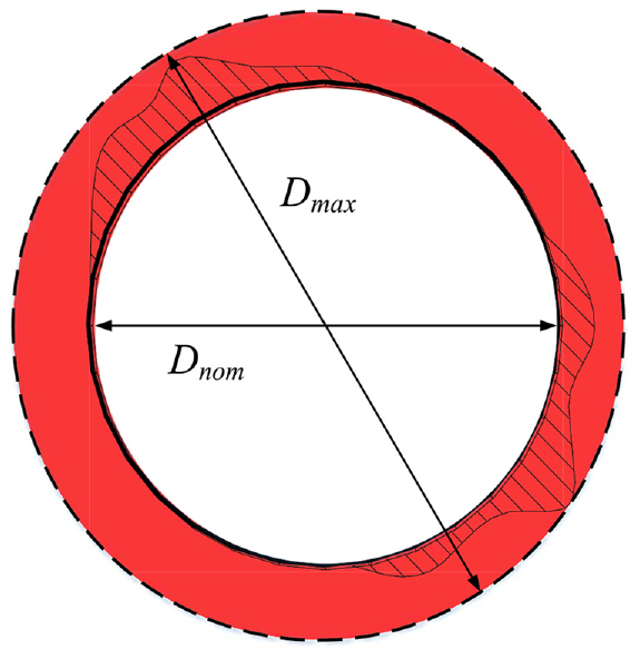
Schematic diagram of delamination factor.
As shown in Figure 15, under the same machining parameters, the exit delamination area of CFRP caused by helical drilling with ultrasonic assistance is smaller than that of conventional drilling. This is because the axial force is the main factor affecting delamination. The helical drill’s transverse cutting edge performs negative rake cutting during the machining process, which relies on extrusion and twisting friction to achieve fiber fracture, resulting in a large axial force. If the main cutting edge cannot cut the fiber bundle in time, it will cause delamination and burrs along the direction of weak interlayer bonding strength. However, when ultrasonic vibration is applied, the transverse and main cutting edge obtain a large impact velocity. Therefore, the transverse cutting edge no longer solely relies on extrusion and twisting friction to cut the fibers but systematically cleaves the carbon fiber bundles, which is more conducive to fiber bundle cutting.

Comparison of exit morphology of the twist drill.
Dagger drilling technique is a combination of drilling, expanding, reaming. As shown in Figure 16, when the rotational speed is 3000 mm/min and the feed speed is 75 mm/min, the exit delamination area is much smaller than that of conventional drilling, which is similar to twist drilling with the law of making holes.

Comparison of the outlet morphology of the dagger drill bit.
The change relationship between exit delamination factor and feed speed for two tools in two machining modes is shown in Figure 17. It can be seen that the exit delamination factor with the increase of feed speed also shows an increasing trend on the whole. Under ultrasonic assisted drilling, the maximum reduction of delamination factor at the exit of twists drill hole is 21.8%, and that of dagger drill hole is 13.6%. In addition, the size of the ultrasonic-assisted drilling delamination factor of the twist drill and the size of the exit delamination factor of the dagger drill ordinary drilling are not much different. It can also be seen from it that the exit delamination factor of the twist drill is the largest in conventional drilling, while the dagger drill is the smallest in ultrasonic-assisted drilling, which is mainly due to the drilling-expanding-reaming composite drilling structure (the first top angle of 102°, the second top angle 20°) makes the axial force of drilling smaller than that of twist drilling. It can be seen from Figures 15 to 17 that the exit burrs of ultrasonic-assisted drilling hole are less than that of conventional drilling and the delamination area is the smallest. This is mainly because that the ultrasonic-assisted drilling changes the cutting angle of the tool, which is more conducive to cutting off the fibers, reducing the generation of defects in the hole making.

Comparison of exit delamination factors at different feed speeds.
Conclusions
The experimental results of ultrasonic-assisted and conventional drilling of carbon fiber-reinforced polymer (CFRP) composites using twist (helical) and dagger drills were analyzed regarding the evolution of axial drilling forces. The following conclusions were drawn:
(1) Under the action of ultrasonic vibration, the cutting edge trajectory of the tool changes, achieving periodic intermittent cutting, reducing the contact time between the drill and workpiece, and reducing tool wear. In addition, the ultrasonic vibration improves the cutting condition of the chisel edge, that makes it change to play an important role in drilling and impacting with a certain cutting speed from extruding and scraping cutting. At the same time, it also increases the instantaneous cutting speed of the main cutting edge, which is more conducive to cutting off carbon fibers and reducing axial force.
(2) The time-varying curve of axial force of twist drill and dagger drill is analyzed. In the stable stage of drilling, the axial force of ultrasonic assisted drilling is significantly lower than that of ordinary drilling. Due to the special geometric structure of dagger drill, the change of its drilling force is more complicated.
(3) The UAD could reduce the axial forces of different special tools. The reduction ratio of the twists drill is between 16.5% and 20.6%, and the dagger drill showed the most significant reduction ranging from 23.3% to 30.7%.The fluctuation range of axial force error bar of twist drill is much smaller than that of dagger drill, so twist drill is more stable in the drilling process.
(4) With increased feed rate, the axial forces in both types of tools gradually increased, and the exit delamination factor also shows an overall increasing trend. Compared with conventional drilling, the maximum reduction of delamination factor at the exit of twists drill hole is 21.8%, and that of dagger drill hole is 13.6% under ultrasonic assisted drilling. Among them, the delamination factor of ultrasonic assisted drilling in dagger drilling is the smallest.
(5) The exit morphology quality of UAD for CFRP was superior to that of conventional drilling for both types of tools. The dagger drill benefited from its composite drilling-countersinking-reaming structure, effectively avoiding exit delamination and resulting in neater cutting edges.
Footnotes
Handling Editor: Chenhui Liang
Declaration of conflicting interests
The author(s) declared no potential conflicts of interest with respect to the research, authorship, and/or publication of this article.
Funding
The author(s) disclosed receipt of the following financial support for the research, authorship, and/or publication of this article: This work was supported by Science and Technology Project of Anyang City (grant number 2021C01SF044), Key Scientific Research Projects of Colleges and Universities in Henan Province (grant number 24A460001), Science and Technology Project of Anyang City (grant number 2021C01SF056), Science and Technology of Anyang (Grant No. 2021C01SF028), Key Science and Technology Plan Project of Henan province of China (Grant No. 222102310333), Key Scientific Research Projects of Universities in Henan (Grant No. 22A460001).
Ethics approval
This study complies with the ethical standards set out by Springer. All authors read and approve the final manuscript.
Consent to participate
Not applicable.
Consent for publication
The manuscript is approved by all authors for publication.
Data availability
All authors confirm that all data and materials reported in this paper are available.
Code availability
Not applicable.