
Abstract
In order to solve the disadvantage of tearing and burr damage in axial drilling of carbon fiber reinforced plastics (CFRP), the stiffness at the exit is increased by applying different drilling speed in ultrasonic vibration assisted drilling (UVAD) Firstly, compared with conventional drilling (CD), ultrasonic assisted vibration drilling can realize the separation of axial tool and tool/chip; Secondly, the cutting speed characteristics of ultrasonic assisted drilling at different speeds are analyzed, and the change of cutting speed characteristics of ultrasonic assisted drilling at low speed is obvious; Finally, the change trend of contact rate at different speeds is analyzed. The experimental results show that the stiffness of ultrasonic assisted vibration drilling is significant. Taking the speed of n = 100 r/min as an example, the stiffness of ultrasonic assisted drilling is about twice as high as that of rotary speed n = 2400 r/min, which is about 8% higher than that of ordinary drilling when n = 100 r/min; Hole exit quality of low-speed drilling: compared with CD, the tearing factor of ultrasonic assisted vibration drilling is lower. Therefore, this method provides a way to improve the hole quality of CFRP.
Keywords
Introduction
Carbon fiber reinforced plastics (CFRP) has the advantages of high strength ratio, corrosion resistance, and fatigue resistance, so it is widely used in aerospace and national defense science and technology and other cutting-edge fields, especially the successful development of large aircraft, and more and more composite materials are valued.1,2 The hole processing of CFRP is an essential link in the aircraft assembly process. In the process of prefabrication, the damage of hole wall and orifice caused by improper method or tool wear is a common phenomenon, especially for anisotropic carbon fiber materials, the difficulty of hole making is much higher than that of metal materials. 2
In order to improve the quality of composite hole processing, many scholars have carried out a lot of research. Shan et al. 3 reduced drilling defects by optimizing cutting parameters and pointed out that thrust is an important factor affecting drilling quality. The tool wear is effectively restrained by using double tip drill, and the machining quality of the hole is improved, but there are higher requirements for the tool structure.4,5
As a special machining method for difficult to machine materials, ultrasonic vibration assisted drilling has a series of advantages, such as making the machined parts “rigid,” reducing the cutting force, improving hole making quality 6 and improving processing speed, 7 and ultrasonic vibration is widely used in various difficult to machine materials8,9 and improving surface roughness. 10 Shi et al. 11 pointed out that the better the stiffness, the better the hole making quality. Luo et al. 12 pointed out that there is a minimum chip thickness, which makes the remaining material insufficient to support cutting. With the decrease of stiffness, the thickness of burr increases gradually. The quality of the hole exit largely depends on the stiffness of the exit. The stronger the stiffness is, the lower the tear damage will be, which will have a positive significance for the assembly of carbon fiber hole. Taking the variation characteristics of cutting speed as the starting point, this paper studies the cutting speed characteristics of amplitude at different speeds when the feed speed is constant. The test results show that the cutting speed characteristics not only affects the stiffness of hole exit, but also the removal mechanism of carbon fiber composites.
Kinematics and cutting mechanism analysis of ultrasonic assisted drilling tool
Kinematics analysis of ultrasonic assisted drilling
The drilling process consists of three stages: drilling in, full drilling in, and drilling out. In the drilling out stage, due to the poor support stiffness, the bottom is prone to deformation, which affects the processing quality. In the drilling out stage, due to the poor support stiffness, 13 the processing quality is poor.
Ultrasonic longitudinal vibration drilling (ULVD) and ultrasonic longitudinal torsional composite vibration drilling (ULTCVD) are two common ultrasonic assisted vibration drilling methods. ULVD applies ultrasonic vibration in the feed direction, but ULTCVD applies ultrasonic vibration in the feed direction and rotation direction at the same time, as shown is Figure 1.

Schematic diagram of ultrasonic vibration assisted drilling.
The trajectory of a point on the outer contour of ULTCVD can be expressed as follows 14 :

Where, x is the rotation angle, rad; ω is the rotation speed, rad/s; δ is the torsional vibration amplitude, mm; y is the longitudinal displacement, mm; vf is the longitudinal feed speed, mm/s; a is the longitudinal vibration amplitude, mm; f is the ultrasonic frequency, Hz; r is the tool radius, mm; When δ is 0, it is the expression of ULVD. When a is also 0, it is the expression of CD. The trajectories of different vibration modes are shown in Figure 2. Figure 2 is the trajectory diagram of one point of the cutting edge of three different machining methods along the rotation direction and feed direction respectively. It can be seen from the figure that the trajectory of CD is a straight line along the rotation direction and feed direction. ULVD presents a periodic forward backward situation in the feed direction, but ULTCVD presents a periodic forward backward situation in both feed direction and rotation direction.
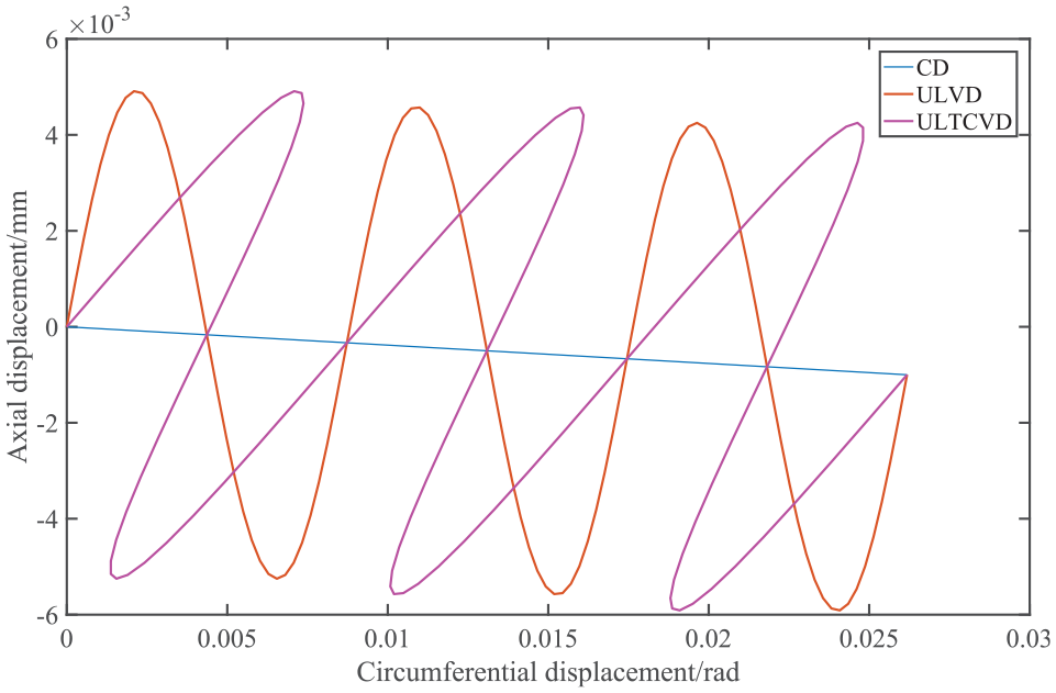
Tool outer edge point in different modes of vibration.
Mechanism analysis of exit damage in ultrasonic assisted drilling
The tear and burr at the exit are important factors affecting the quality of the hole, especially the assembly of laminated materials. The excessive axial force will directly affect the delamination in the drilling process. At the same time, with the continuous drilling, the support stiffness at the bottom of the work-piece gradually decreases, and the deformation or delamination area at the bottom is larger than that of the orifice area. The excess part cannot be removed by the main cutting edge, and eventually form tear and burr damage. If the area does not exceed the range of the orifice, the sharpness of the main cutting edge will directly affect whether the orifice has burr, tear, and other damage. 13 Most of the axial force is generated by the chisel edge. Therefore, if the tearing deformation of the chisel edge on the carbon fiber material can be reduced and the main cutting edge can cut off the carbon fiber in time, the quality problem of the hole exit can be effectively improved.
Influence of transverse edge of vibration drilling on exit damage
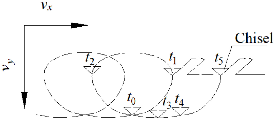
In the process of ordinary drilling, because of the negative rake angle of the chisel edge, it is rather material extrusion than cutting, and the schematic diagram of the cutting process is shown in Figure 3.13,15 Ultrasonic vibration is applied in ultrasonic assisted drilling, which leads to the change of its trajectory. For ordinary drilling, its trajectory is a straight line along the coordinate system (Circumferential displacement–Axial displacement), but UVLD and UVLTCD show periodic vibration, and the displacement of the two kinds of vibration drilling has changed, which is expressed in Figure 2. Especially when ultrasonic vibration is applied in two directions at the same time, it is no longer in contact all the time like ordinary cutting. At the same time, the direction of cutting speed in the periodic process of cutting (t0–t1–t2–t3–t4) is constantly changing, which leads to the change of its rake angle and relief angle. The tool angle changes during cutting, as shown in Figure 4. 16

Cutting diagram of transverse edge.
Schematic diagram of elliptical vibration cutting path.
Considering that a single fiber is cut, take the chisel edge as an example, assuming that the length of the cutting section is l and the mass is m, from the microscopic point of view, the fiber is deformed under the pushing action of the tool. The schematic diagram is shown in Figure 5, and it can be obtained from the momentum theorem 17 :


The effect of transverse edge on tear damage.
Where v0 is the initial velocity, v is the instantaneous velocity at a point of the fiber shear section, s is the cross-sectional area, τ12 is the shear stress, and m is the mass of the carbon fiber shear section. Equation (2) can be rewritten as follows:

It can be seen from equation (3): in unit time, when the shear stress τ12 reaches the ultimate strength rapidly, the fiber is cut off before deformation and chips are produced. 18 The faster the cutting speed changes, the greater the shear force; The greater the shear force, the lower the deformation degree of carbon fiber material, inhibit the generation of tear, and help to improve the processing quality. This also means that the faster the cutting speed changes, that is, the greater the difference of cutting speed. The relationship between velocity and angular velocity is as follows,

Where, v is a certain tangential speed of the main cutting edge of the drill bit. According to Pythagorean theorem, the resultant velocity can be obtained from the derivation of equation (1) 19 :

In the process of drilling, ultrasonic vibration is applied to the two directions, when

Changing trend of cutting speed with time (n = 100 r/min, a = 0.0038 mm, vf = 0.25 mm/s, δ = 0.0005 mm, f = 33950 Hz): (a) global graph and (b) partial enlarged drawing.

Changing trend of cutting speed with time (n = 1500 r/min, a = 0.0038 mm, vf = 0.25 mm/s, δ = 0.0005 mm, f = 33950 Hz): (a) global graph and (b) partial enlarged drawing.

Changing trend of cutting speed with time (n = 2400 r/min, a = 0.0038 mm, vf = 0.25 mm/s, δ = 0.0005 mm, f = 33950 Hz): (a) global graph and (b) partial enlarged drawing.
Influence of rotating speed on contact rate in vibration drilling
Whether the main cutting edge can completely remove the fiber in a short time directly affects the final machining quality of the hole. Because of the spiral structure of twist drill, it is possible to vibrate in torsion direction. Therefore, in terms of rotation direction, when the cutting parameters reach certain conditions (regardless of the influence of feed direction vibration), the tool/chip separation can be realized,

Where, δ is the torsional vibration amplitude, mm; f is the ultrasonic frequency, Hz; ω is the tool rotation angular velocity, rad/s. In order to describe the separation of tool and chip, the duty cycle is introduced,20,21

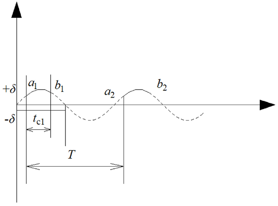
The smaller the duty cycle is, the longer the tool/chip separation time is, and the lower the average cutting force is. Figure 9 is the schematic diagram of cutting separation cutting between tool and chip,19,20 where a1 is the beginning of cutting, the end of cutting at b1, and the beginning of cutting at a2, which is a cutting cycle T.
Schematic diagram of tool/chip cycle separation.
In combination with formulas (1) and (7), it can be concluded that:


Simultaneous equations (7)–(9) can be obtained as follows:

In the process of drilling, from the angle of rotation direction, when the ultrasonic amplitude and frequency are fixed, the cutting speed directly affects the change of duty cycle. Figure 10 is a schematic diagram of the change of the duty cycle with cutting speed, in which the ultrasonic amplitude is 0.0005 mm and the frequency is about 33,950 Hz. If the tool diameter is 6 mm, the corresponding speed n is about 0.105 m/s. the tool/chip duty cycle is still obvious. When the cutting speed and frequency remain unchanged, the duty cycle shows a downward trend with the increase of amplitude, as shown in Figure 11 (The influence of longitudinal vibration on the duty cycle in the rotation direction is ignored).

Contact rate changes with cutting speed (δ = 0.0005 mm, f = 33,950 Hz).

Duty cycle changes with δ (v = 0.4 m/s, f = 33,950 Hz).
Combined with the change of cutting speed difference and the duty cycle, the main cutting edge can give full play to the cutting ability, and the cutting speed should be controlled in an appropriate range, not the faster the better. In addition, Figure 12 shows the change trend of cutting thickness with rotation speed when the feed speed is 15 mm/min. The larger the cutting speed is, the smaller the feed rate of each tooth is. When the rotating speed exceeds 1000 r/min, the cutting thickness is less than 10 μm (close to the diameter of the fiber), which means that when the drilling depth is equal, the longer the tool stays in this section, and the drilling is almost close to the “grinding” mode.
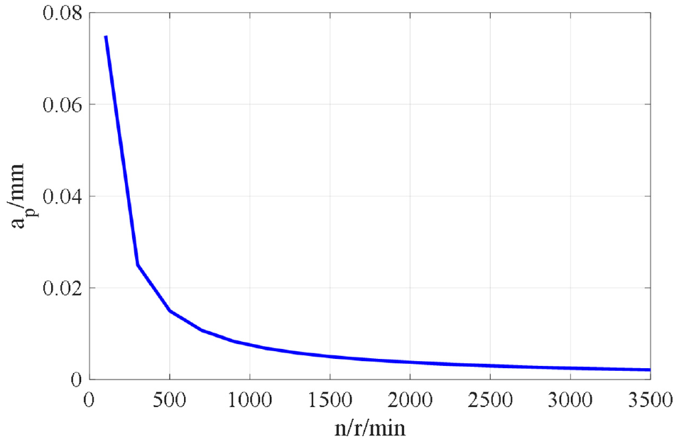
Variation trend of cutting thickness with rotating speed (vf = 15 mm/min).
In the process of drilling, the angle between cutting edge and fiber is constantly changing. In order to analyze the influence of cutting depth on fiber removal, take 0° as an example, as shown in Figure 13.18,22 For the tool, the tool is not absolutely sharp (i.e. the blunt radius of the tool is not 0). When the cutting depth is close to or less than the diameter of the fiber, it is also less than the blunt radius of the tool. At this time, the marking rake angle of the tool γ0 changes, and a negative rake angle γ1 20 is formed at the blunt radius. When the fiber is rolled by the tool arc, the fiber will deform downward, as shown in Figure 13(a). It is not easy to produce chips, so that cutting becomes “grinding” and cutting force becomes “friction.” Rolling at the blunt radius of the cutting tool will impact and disperse the composite material bonded with carbon fiber by resin, and then the constraint effect of the fiber will be reduced, which will not only affect the effective removal of the fiber, but also increase the fiber tearing.

Schematic diagram of fiber removal at different cutting depth: (a) when the cutting depth is close to the fiber diameter and (b) when the cutting depth is greater than the fiber diameter.
When cutting between A and B (the cutting thickness is greater than the diameter of the fiber), as shown in Figure 13(b), due to the ultrasonic vibration applied by the tool in the direction of rotation, it can be seen from the previous text that the cutting speed of the tool changes greatly, the fiber is removed in the extreme time, and the area above a will be lifted to form chips.
18
With the increase of rotating speed, the difference of cutting speed increases only when
However, considering the above situations of “tool pulling and fiber rolling,” the axial force in the stable stage of the tool drilling process is not stable, and the overall continuous reduction is significantly higher than that in low speed drilling.
Realization of torsional motion
Inspired by the design of ring inclined beam section, when the longitudinal vibration meets the spiral groove, the vibration will be decomposed in the direction next to the spiral groove, as shown in Figure 14.
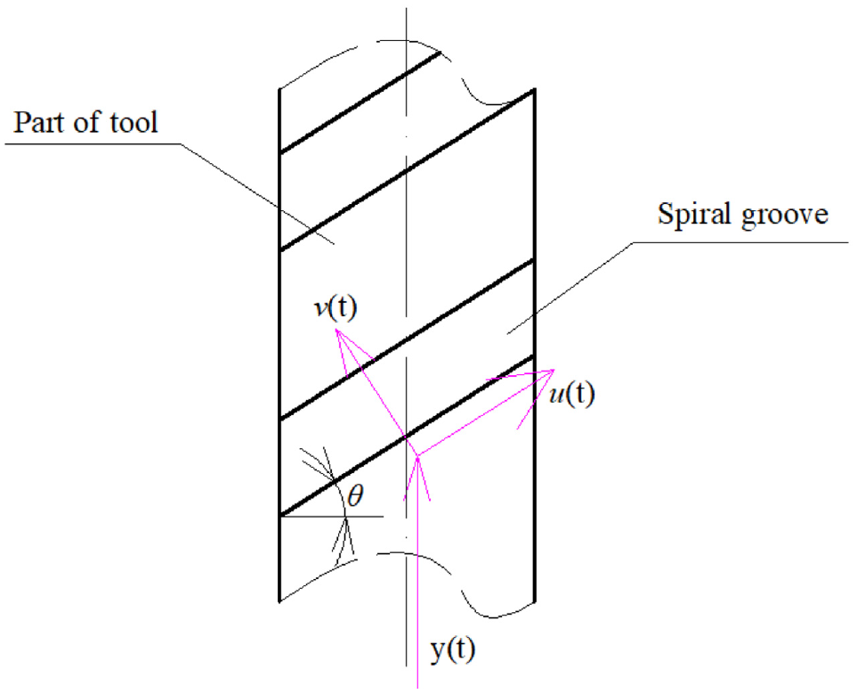
Decomposition of longitudinal vibration.
θ is included angle between spiral groove and vertical axis plane. y(t) indicates longitudinal vibration. v(t) vibrates perpendicular to the spiral groove and u(t) vibrates along the spiral groove. The vibration frequency of u(t) is tool local vibration frequency, which local bending vibration will occur. From the cross-section of the ring problem, the bending vibration effect can be approximated as the torsional vibration of the circumferential surface of the ring.14,23
Drilling test
Test tools, materials, and test parameters
Because the amplitude of torsional vibration is lower than that of longitudinal vibration, and considering the influence of cutting speed characteristics, referring to relevant literature, 21 the following parameters are determined for drilling test processing, as shown in Table 1.
Parameters of drilling.

The tool is made of cemented carbide with a diameter of 6mm. In the experiment, T700 unidirectional CFRP was used. The diameter of the fiber was about 7 μm. The ultrasonic frequency was about 33.95 kHz. The longitudinal and torsional vibration amplitudes were about 3.8 and 0.5 μm respectively. The amplitudes of longitudinal vibration and torsional vibration are measured by laser displacement sensor (LK-G10).
Construction and condition of test system
The VMC850 machine tool is selected for the experiment, and the ultrasonic transmission is realized by non-contact way. The cutting force is collected by the Kistler dynamometer 9257b in the experiment. After the hole is machined, the morphology of the hole is observed by the ultra depth of field three-dimensional microscope (VHX-2000). The experimental processing site is shown in Figure 15

CFRP test chart of ultrasonic assisted vibration drilling.
Test results and discussion
Trend of exit stiffness
Figure 16 shows the trend of axial force at different speeds. It can be seen that when the cutting parameters are n = 200 r/min and vf = 15 mm/min, the overall axial force of ordinary drilling is greater than that of ultrasonic drilling. The reason for the above results is that ultrasonic vibration drilling realizes the separation of two directions, and the time to really participate in drilling is reduced. In addition, the cutting speed difference caused by vibration drilling makes the carbon fiber reach the strength limit in extreme time, and it will be cut off before deformation, resulting in small deformation, so the overall cutting force of ultrasonic drilling is small. 17

Axial force of two kinds of vibration drilling at different speeds: (a) CD (n = 200 r/min), (b) ULTCVD(n = 200 r/min), and (c) ULTCVD (n = 100 r/min).
In the process of drilling out, due to the lack of support of the material, the stiffness decreases, and the material begins to deform under the action of the cutter, which makes it difficult to completely remove the fiber. If the stiffness is better, the material deformation is smaller. Combined with the deformation effect of ultrasonic vibration cutting speed, it is more favorable for the removal of fiber. Assuming that the stiffness value of drilling in is 1, the exit stiffness can be inversed indirectly by equation (11) Should,

Among them, Fmax is the maximum value in the drilling stage and F2 is the critical value of drilling stability stage and drilling out stage. It should be pointed out here that the axial force in Figure 16(c) increases almost in the whole drilling stage, and there is an obvious downward trend until the beginning of the drilling stage, that is, there is almost no yielding deformation in the drilling stage, and the stiffness value in this case is determined as 1.
Figure 17 shows the change trend of the stiffness values of the two vibration modes with the rotation speed. It can be seen from the figure that the stiffness decreases with the increase of rotating speed. The overall stiffness value of ultrasonic drilling is slightly larger than that of ordinary drilling. This is because in the drilling process, it is assumed that there is a critical cutting thickness h. When the drilling thickness is less than h, the exit area is deformed. On the contrary, when the drilling thickness is greater than h, the deformation of the drilling exit remains unchanged (or minimal), that is, the axial force F in the drilling process remains unchanged. The higher the speed vf, the smaller the feed rate per tooth (fr). Assuming fr < h, then: when the cross edge reaches below this position, the exit deforms along the feed direction, and the actual feed rate per tooth will be less than the set feed rate, resulting in the decrease of the axial force F2 of the tool acting on the material, and k according to equation (11). Within the minimum chip thickness range, each time the tool rotates, it pushes the remaining materials at the exit once. The more the pushing times are, the greater the deformation will be. The actual feed rate per tooth will be lower than the set feed rate, resulting in lower and lower axial force; Therefore, the higher the rotating speed, the more times of pushing. At the same time, the higher the rotating speed, the cutting speed does not change quickly. Therefore, with the increase of rotating speed, the lower the stiffness value.

Variation trend of stiffness values at different speeds (exit).
The cycle separation of ultrasonic longitudinal torsional compound vibration drilling reduces the net cutting time, changes rapidly in cutting speed, enhances the cutting ability of the cutting edge, reduces the average cutting force, and the deformation of the exit area is small, that is, the stiffness value is large. The realization of the law of stiffness value changing with cutting parameters, and the influence of amplitude on cutting speed accounts for a large part.
Hole exit quality
Burr and tear damage
The number and length of burr directly affect the machining quality of the hole. Figures 16 and 17 show the hole exit topography of ultrasonic and common drilling vibration modes. Among them, Figures 18 and 19 respectively show the exit topography of the two drilling methods when the rotation speed n = 100 r/min, vf = 15 mm/min and the rotation speed n = 2400 r/min, vf = 15 mm/min. It can be seen from the figure that the number of burr and smooth area of orifice in low-speed ultrasonic machining are better than others. This is because, on the one hand, due to the small amplitude of rotation direction, low-speed ultrasonic machining can achieve tool/chip separation in rotation direction, and carbon fiber will produce continuous deformation, which may further reduce the damage such as tearing and burr; On the other hand, it can be seen from Figures 6 to 8 that: the increase of rotation speed does not mean that the change of cutting speed is greater. On the contrary, the change of cutting speed is greater when drilling at low speed, which is beneficial to the removal of carbon fiber. It not only reduces the cutting force, but also suppresses the damage such as burr and tear.

Two ways of processing export morphology (n = 100 r/min, vf = 15 mm/min): (a) exit entrance of CD and (b) exit entrance of ULTCVD.

Two ways of processing export morphology (n = 2400 r/min, vf = 15 mm/min): (a) exit entrance of CD and (b) exit entrance of ULTCVD.
The trend of damage factors
In this test, it is assumed that the feed rate remains unchanged, and the higher the speed, the lower the feed rate per tooth. It can be seen from Figure 11 that when n = 1000 r/min, the cutting thickness is close to the diameter of the fiber, which is not conducive to the cutting. There is a similar “grinding” situation, so that the fibers bonded by resin are under the action of this “friction.” Under the action of this “friction,” the fibers confined by the matrix lack support and fixation, which are not conducive to removal, and finally form more burrs, as shown in Figure 19(a). In addition, the impact of ultrasonic assisted vibration on the composite material with very thin cutting thickness will aggravate the situation of fiber scattering, and the burr produced is all over the hole, as shown in Figure 19(b). It brings difficulties to subsequent burr removal and is likely to cause secondary tearing. In low-speed drilling process, due to low speed and relatively large cutting thickness, the shape of burr produced is relatively consistent as a whole, because the quantification of burr damage needs to be related to the width and length of burr. 22 However, the burr morphology of high-speed drilling is different and staggered with each other, which is not easy to quantify. However, it can be seen intuitively that the number of burrs drilled at low speed is less. The surrounding distribution area is relatively low. In addition, it can be seen that the edge smoothness of low-speed hole is much higher than that of high-speed drilling. This is because the separation of rotation direction during low-speed drilling makes a point at the outer edge of the cutting edge repeatedly roll the surface of carbon fiber work-piece, the convex part is rolled flat, and the concave part is filled flat, which improves the smoothness of the hole. Obviously, the overall quality of low speed drilling is relatively high. In order to further evaluate the quality of low-speed drilling common machining and ultrasonic machining, and taking into account the error caused by different burr evaluation standards and different burr shapes in actual measurement, the evaluation method of delamination factor is used to evaluate the two machining methods. There are many methods to solve the delamination factor (Fd).24,25 In order to facilitate the solution, the following methods are adopted in this test, as shown in equation (12), 25

Where Dd is the diameter of the tearing area and D0 is the diameter of the tool. The scope of the tearing area is a circle with the center of the machined hole as the center and the farthest position from the center of the machined hole to the continuous tear area at the exit as the radius, as shown in Figure 20. The continuous tear at the exit (along the circumferential direction) is measured as the main area. The change trend of damage factors of the two drilling methods is shown in Figure 21. It can be seen from the figure that the damage factor of ultrasonic longitudinal torsional vibration drilling is lower when the rotation speed is n = 100 r/min.

Tearing area of a hole.

Tearing factor in low speed drilling (n = 100 r/min).
Conclusion
Through the analysis of drilling mechanism and experimental research of CD and UVLTCD, the following conclusions are obtained in the given range of experimental parameters,
In UVLTCD, the cutting speed at low speed changes rapidly, which enhances the cutting ability of the cutting edge, reduces the tearing degree of materials in the cutting process, and improves the stiffness of the exit of hole. With the increase of rotation speed, not only the duty cycle η begins to increase, but also the feed rate per tooth decreases, resulting in the decrease of exit stiffness k.
With the increase of amplitude, the trend of the duty cycle shows a downward trend; However, the duty cycle increases with the increase of rotating speed.
From the morphology of the exit and the analysis of the results, when the feed speed and amplitude are fixed, the number of burrs at the exit increases with the increase of rotating speed; When the rotating speed is low, UVLTCD realizes the tool/chip separation and the Fd of UVLTCD is lower than that of CD.
Footnotes
Handling Editor: Chenhui Liang
Declaration of conflicting interests
The author(s) declared no potential conflicts of interest with respect to the research, authorship, and/or publication of this article.
Funding
The author(s) disclosed receipt of the following financial support for the research, authorship, and/or publication of this article: The manuscript is supported by the National Natural Science Foundation of China (51675164).