
Abstract
The Trombe wall is a passive solar heating system that aims to mitigate heating load. However, its efficiency is impeded by significant heat loss through the glazing. To address this issue, a novel technique has been developed that involves partial evacuation of the space between the storage wall and the glazing. This approach, which has already found successful application in double-paned windows and solar collectors, is examined in this study to evaluate its impact on the performance of an isolated Trombe wall. An effectiveness criterion based on the ability of a system to preserve its stored thermal energy is defined and used for assessing the performance of a vacuumed system relative to a non-vacuumed one. An experimental test cell, composed of a solid concrete wall serving as a thermal storage and a glazing separated from the wall by an air gap, facing south is constructed in Kirkuk, Iraq. The wall is insulated at all its sides except the side facing the glass. The gap has been sealed meticulously to maintain a vacuum. Due to unrepeatability of the testing conditions experimentally, a numerical method and a computer code is also developed for simulation of the system. Measurement results obtained from the test cell under normal atmospheric pressure and a gage pressure of −0.3 bar of the air gap are used to validate the numerical method. The code is then used to simulate the performance of the system under the same ambient conditions but at different vacuum pressures of the air gap. Results obtained from the numerical tests show that partial evacuation of the air gap can be an efficient way to enhance the performance of the Trombe wall and the absolute pressure of 0.1 bar results in the most significant increase in the effectiveness of the studied model.
Introduction
In recent decades, population growth along with technological development have had a significant impact on increasing energy consumption. Mostly produced from crude oil and natural gas, the increase in energy demand has caused an unusual upturn in the emission of toxic gases, about 46.75% between 2000 and 2021, 1 which negatively affected the environment and led to alarming climate change. 2 Therefore, it is urgent to remedy the situation and attempt to reduce the negative effects. Among many feasible options, renewable alternative energy sources seem very promising in conjugation with the efforts to raise the efficiency of clean energy dependent systems. Worldwide, building sectors represent the largest energy consumer which is about 40% of total energy consumption making buildings to be the key master in applying any suggested remedies. Among many renewable energy sources, solar energy is the most important source because of its availability and versatility of use. Approximately 50% of consumed energy in buildings is used up by ventilation, heating, and air conditioning systems.2–4 The annual heating demand can be reduced up to 25% by utilizing passive solar heating systems through solar roofs, solar chimneys, Trombe walls, and more. 5 Due to its simple construction, low or no maintenance requirements as well as zero operation cost, Trombe wall is widely employed as passive solar system. 6 Furthermore, Trombe walls can reduce about 30% of energy consumption when they are integrated into the building constructions. 7 A classical Trombe wall is made of massive wall that is constructed from different building materials and service as a thermal storage wall. Moreover, glazing is also installed at a small distance from the wall forming an air channel between the wall and glazing. However, in the ventilated type Trombe wall, usually two ventilation ports are made in the storage wall, one at the top and one at the bottom allowing air circulation between the room and the air channel. 7
In the regard of performance investigation and improvement along with expanding the functionality of Trombe wall, several theoretical and experimental studies have been conducted and a numerous innovation are introduced to the traditional Trombe wall design. Concerning the thermal performance, Yedder and Bilgen 8 conducted a numerical performance investigation of a classical Trombe wall with assumption of 2-D laminar flow in the air channel. Using computational fluid dynamics (CFD) analysis, a numerical investigation of a Trombe wall performance and its impact on energy demand are correspondingly performed by Bajc et al. 9 Utilizing CFD as well, Mawlood and Abbas 10 developed a numerical method for solving the case of unsteady 2D turbulent flow in a Trombe wall system using parallel computing method to reduce computation time. Jaber and Ajib 11 analyzed the performance of a Trombe wall fitted to a residential building in Jordan using TRNSYS simulator and they reported that from the economical and thermal point of view, the area ratio (ratio of the Trombe area to the total wall area) of 37% can lead to optimal effects. Using same simulator, Abbassi et al. 12 predicted the performance of Trombe wall located in Tunisia and showed that the annual heating can be reduced by 50% using 4 m2 Trombe wall and 77% energy saving can be achieved when the area is increased to 8 m2. An annual energy saving of 20% for a building equipped by Trombe wall is also obtained by Bojić et al. 13 in France. The effect of construction parameters of the Trombe wall component on the thermal performance is investigated by Fares. 14 To improve the thermal behavior of Trombe walls, Bilgen 15 and Wu et al. 16 studied the effect of attaching fins to the surface of the storage wall. An improvement in the Trombe wall performance is observed. However, to increase the thermal storage capacity of the massive wall without increasing the dead weight of the wall, a layer of phase change materials (PCM) is added to the wall.17,18
The two drawback points of any Trombe wall are the low efficiency due to heat losses during the night and cloudy days as well as the overheating in summer seasons. 19 According to Sergei et al., 20 the heat losses from the air gap through the glass can reach 60% of the total incident radiation and the glass type directly affects the associated heat losses in Trombe wall. Zalewski et al. 21 showed that the energy saved using low emittance double glazing is higher than that of standard double glazing in the range 143%–177%. In the same direction, Stazi et al. 22 also studied the effect of glazing on the energy performance of the Trombe wall. The insulating rate during evening and night for double glazing was shown by Koyunbaba and Yilmaz 23 to be higher than with single glazing. Whereas the solar radiation gain for single glazing during the day time is higher due to its higher transmissivity. Kaloyanov et al. 24 also illustrated that the heat losses can be reduced by 35% via double glazing as they investigated unvented Trombe wall performance with single and double insulating glazing.
The integration of shading devices, such as roller shutter, shading curtain, overhang, and venetian blinds into Trombe wall serves the purpose of decreasing heat losses in winter and reducing the overheating in the summer. Studies by Chen et al. 25 and Stazi et al. 26 have shown that the use of Roller shades in the air gap of a Trombe wall can result in a reduction in the heat losses by 20%–40% in the winter and decreasing in the cooling load in the summer compared to a Trombe wall without roller. As reported by Refs,27–29 the utilization of venetian blends has improved the conventional Trombe wall efficiency by reducing the cooling load in the range from 2.5% to 5.8%, and decreasing heat gain from the solar radiation during summer. The implementation of shading devices in the air gap or additional glazing may reduce the heat losses, however it also reduces the amount of solar radiation that reaches the thermal storage wall. This reduction in solar radiation is counter to the desired outcome of allowing maximum solar radiation to reach the storage wall. This issue is not limited to Trombe walls and is also encountered in solar collector systems and typical residential glazing. To address this problem, Ghosh et al. 30 viewed some possible solutions as following: using multiple glazing panes, using aerogel material, charging heavy inert gasses in the gap, and evacuation of the space between the two glazing panes. They applied the last method to a double pains window and reported that reducing the pressure can inhibit the convection and reduce the thermal conductivity of the air, consequently reducing the heat losses. They also reported that the vacuum glazing can be operate with heat loss less than that of normal double-glazing by amount of 53% while offering nearly same amount of solar radiation gain. The degree of heat losses reduction can be regarded thought the overall heat transfer coefficient (U, W/m2 °C). According to a review work by Collins and Simko, 31 the achieved U values of vacuum glazing is ranged from 3.0 W/m2 °C for vacuum glazing without coating to 0.8 W/m2 °C for glazing with low emittance coating in the inner side. To further reducing the U value of the glazing, Manz et al. 32 predicted the calculation of the U value to be 0.2 W/m2 °C with a triple vacuum glazing.
Numerous research studies have explored the use of vacuum technology to reduce heat losses in flat-plate solar collectors. As stated by Eaton and Blum, 33 evacuating the flat plate solar collector to a pressure range of 150–3500 Pa can effectively eliminate natural convection losses and therefore result in a significant increase in collector efficiency. A reduction in the gap pressure to below 150 Pa can also cause a decrease in the thermal conductivity of air. Moss et al. 34 conducted an experiment on a flat plate solar collector and found that at a pressure of 0.5 Pa, the U value decreased from 7.4 to 3.6 W/m2 °C. This led to an increase in efficiency from 36% to 56% at ΔT = 60°C and solar radiation of 1000 W/m2. Henshall et al. 35 also reported similar results where the efficiency of the solar collector improved with an evacuated air gap at a pressure of 0.001 Pa where the U value decreased from 2.23 to 0.86 W/m2 °C. Abbass and Abduljabbar 36 conducted a study on the effect of front panel material type and vacuum application on the thermal efficiency of a solar collector. They found that transparent Polycarbonate sheets had 22% less energy loss than glass sheets. Furthermore, utilizing a 4 mm Polycarbonate cover with high transmittance and vacuum spacing led to an overall collector thermal efficiency of approximately 70%, which was notably higher than the 57% efficiency of a non-vacuumed Polycarbonate cover with double layers.
From the above review, it can be concluded that about 60% of the incident radiation on a Trombe wall may be lost through the glazing by convection and radiation. The energy loss is the main reason of inefficiencies of the Trombe wall system. Consequently, it is a requisite to quantify the loss in energy and explore the solutions to increase the efficiency of a Trombe wall as much as possible. However, the challenge point here is to reduce the heat losses through the glass without compromising the transmission of the solar radiation into the Trombe wall. As viewed earlier, for a double panes glazing and a flat plate solar collectors, this objective has been achieved with a valuable success via evacuating the air gap. The current work attempts to apply and investigate the same technique but with Trombe wall system aiming to improve the system performance under real weather conditions. For this purpose, an experimental prototype is built and tested under normal atmospheric pressure and a moderately evacuated air gap. Mathematical modeling employing CFD approach is then used to generalize the outcomes and assess the effectiveness of partial evacuation of the air gap on the thermal performance of the system.
Materials and methods
Figure 1(a) shows a Trombe wall system combined to a conditioned space. A part of the thermal energy gained from the solar radiation incident on the outer surface of the thermal storage wall is transferred to its inner surface through the wall by conduction and another part will be lost through the air gap and glazing to the surrounding air. The energy at the inner surface of the wall then propagates to the inner space by a combined mechanism of convection and radiation. A portion of the heat transferred to the room is gained by the air causing its temperature to rise while the reaming heat will be lost to the surroundings through the walls, ceiling, and ground. This interaction between the Trombe wall and the room makes it difficult to analyze its performance precisely. Thus, it is becoming an essential task to isolate the Trombe wall system from the room to eliminate interaction between them and to concentrate more on the thermal behavior of the Trombe wall alone. To focus on the impact of heat loss through the air gap and glazing on the effectiveness of the Trombe wall system, the present study suggests an isolated test cell that represents a Trombe wall system as shown in Figure 1(b). In the following subsections, the experimental setup along with the numerical formulation of the system are described and the solution method is presented accordingly.

(a) Trombe wall system attached to a room and (b) an isolated Trombe wall test cell.
Experimental setup
To study the effect of evacuation of the air gap on the thermal performance of a Trombe wall an experimental prototype is built and supplied with the necessary measuring devices and instruments. The test facility is constructed in Kirkuk city of Iraq, located 44.38° east and 35.466° north. The test model consists of a concrete solid wall facing south with dimensions of 105 cm × 105 cm front area and 20 cm wall thickness and painted with mat black color. To minimize heat transfer to the ground, thermostone blocks of 20 cm × 20 cm are inserted under the wall at the construction time. The top and the sides of the wall as well as the backside are insulated by a 10 cm thick Expanded Polystyrene (EPS) sheet. A 6 mm thick transparent acrylic glass is used as the glazing of the Trombe wall. This particular type of glass is selected after conducting a transmissivity test on various options, including 2 mm normal glass, 6 mm clear acrylic, and 10 mm tempered glass. Figure 2 indicates that the clear acrylic demonstrated the highest transmissivity to solar radiation among the tested glasses. Furthermore, the acrylic glass is relatively flexible and less prone to shattering than other types of glass. To create the air gap and provide support for the glazing, an 8 cm thick wooden frame is attached to the wall. The frame and the glazing are held to the wall using a series of screws with a diameter of 8 mm, spaced 15 cm apart. In order to avoid air leakage between the frame and wall during a vacuum condition, the air gap is lined with a 0.6 mm thick galvanized plate. The edges of the plate are bent inward and fitted with a hollow rectangular metal pipe. A 3 mm thick layer of nano double sided adhesive tape, measuring 4 cm in width, is interposed between the plate edges and the covering glass to impede any air leakage. A pump out-stub is welded to the plate for the purpose of evacuation. The glass is further supported against deformation by a number of wooden pillars inserted between the glass and the wall. The pillars are cylindrical in shape with 2 cm diameter and spaced from each other 8 cm apart vertically and horizontally. As a final step, the model was enveloped in nylon to ensure that air, moisture, and rain do not seep between the insulation and the wall. Figure 3 shows a photograph of the front and side views of the model. The densities of the concrete wall, the glazing and the insulation are determined by simply measuring the mass and volume of their samples. Thermal properties are obtained from the literature and slightly adjusted by numerical experimentation using a numerical method described below. Table 1 presents all the properties of the materials used in this work. K-type thermocouples with an accuracy of ±0.3°C and 5 m long extension wires are employed after calibration to measure the temperature distribution in the system. A total of 27 thermocouples are placed in the wall within three planes (P1, P2, and P3) along the wall thickness with nine thermocouples in each plane as detailed in Figure 4. Planes P1 and P3 are approximately 2 cm from the front and back surfaces of the wall, while P2 is the central plane of the wall. The thermocouples are equally spaced 30 cm apart from each other in the horizontal and vertical directions. In addition, three thermocouples are pasted to the plate surface. The temperature of the exterior surface of the glazing and the ambient temperature are measured by the same type of thermocouples. The data from the thermocouples are collected every minute through a 64-channel PZ1064S multi-channel temperature recorder. A TES 132 data logging solar power meter is used to measure the solar radiation incident on a vertical surface every minute. In addition, an anemometer, specifically the PR-3000-FS-V05 model, is employed to measure wind speed also at 1-min intervals.
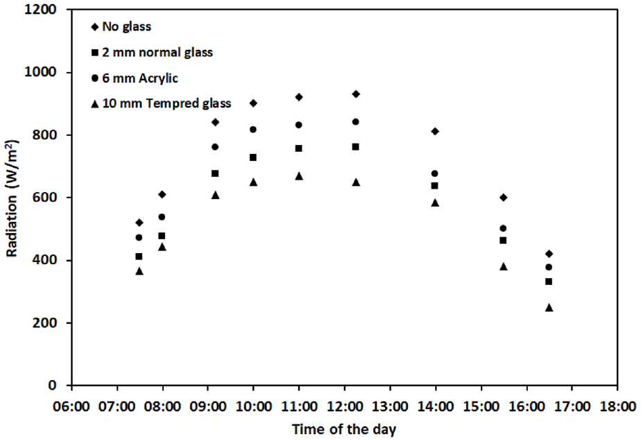
Transmissivity measurement of different type of glasses.
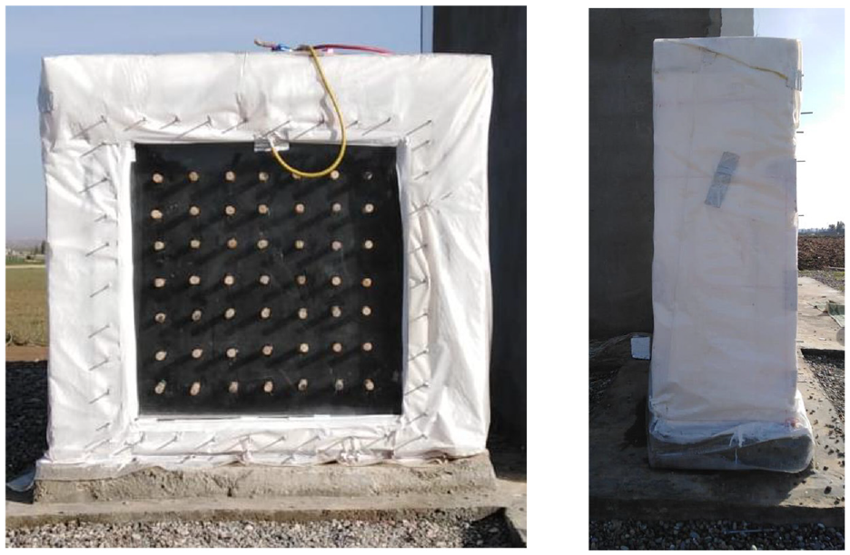
Experimental Trombe wall test cell.
Materials properties used in the construction of the test cells.


Locations of the thermocouples in the Trombe wall test cell.
Mathematical modeling and numerical solution
A two-dimensional mathematical model of the principle of mass, momentum, and energy conservation is used to simulate the unsteady air flow and heat transfer within the isolated Trombe wall system described above. The air is treated as incompressible in the considered range of temperature variation, whereas the buoyancy effect is combined into the momentum equation by the Boussinesq approximation. The governing equations employed for the determination of velocity and temperature distribution within the Trombe wall system can be written as follows. 37
The equation of mass conservation for air flow is:

Where, u and v are the velocity components in x- and y-directions, respectively.
Momentum equation in the x-direction:

Momentum equation in the y-direction:

Energy equation:

Where in equations (2) and (3),


In which
For its simplicity and accuracy, the following zero-equation turbulence model proposed by Chen and Xu 38 is used

where
Rayleigh number, Ra, is utilized to distinguish between natural convection turbulent and laminar flow which is calculated from:

where L is the distance between the sides of the flow channel and
Air density in the air gap under vacuumed conditions is initially calculated by the equation of state and remains unchanged for the whole simulation process.
Boundary and initial conditions
The heat transfer from the outer surface of the glazing and insulation occurs by convection and radiation to the atmosphere. The convection heat transfer from the outer surfaces is calculated from:

where the convection heat transfer coefficient (h) is computed as a function of the wind speed (

The radiation heat transfer from the glazing is calculated from:

where,

The conduction heat at the outer surface of the glass equal to the sum of the heat lost by convection and radiation from the surface and hence:

The solar radiation absorbed by the glazing and the wall surface is included in the source term of the energy equation. The radiation heat transferred among the inner surfaces of the air gap is also added to the source term of the energy equation. The view factors of all the surface elements resulting from the computational grid are determined by Hottels’ crossed-strings method and the net heat radiated by each surface element is calculated by the matrix method described by Özisik. 41
No slip velocity boundary condition is imposed for the air at the surfaces which is considered to be zero in the case of simulation of the normal atmospheric model. Whereas in the case of air vacuum in the channel, the temperature jumps and slip flow boundary conditions are considered and adjusted by Knudsen number according to the following equations42,43:


where V is the velocity in the direction n normal to the solid surface,

in which B is Boltzmann constant and equal to
The Knudsen number (Kn) is defined by:
where L is the distance between the two surfaces that confines the gas (the width of the air gap).
As mentioned previously, the undertaken problem is unsteady so that initial conditions are required to start the simulation process. The initial temperatures of the wall, glass, plate, and the air are obtained from the experimental data and then passed to the program to initiate the simulation.
Solution method
The governing equations (1)–(6) along with the boundary conditions are solved numerically using the finite volume method. Non-uniform structured grids are used in the simulation. The velocity components are computed on a staggered grid to eliminate the possibility of unrealistic pressure oscillations. For the purpose of increasing the accuracy of the results without increasing the number of grids, the grid points are condensed near the solid boundaries where the temperature and velocity gradients are large. A typical mesh for the system is shown in Figure 5. The fractional step method presented by Kim and Moin
44
is used in the present work to advance the solution in time and calculating the new values of the variables (

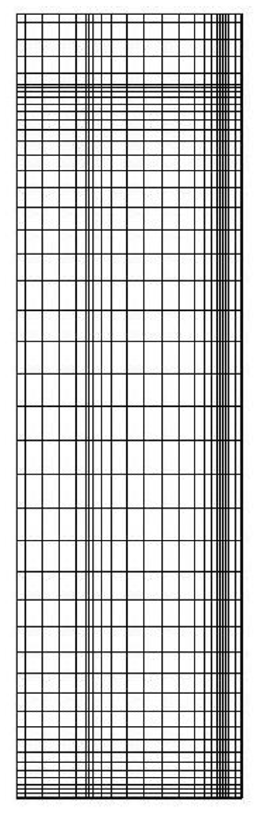
Typical grid points for the test cell.
The pressure correction obtained from the above equation is then used to calculate the pressure and velocity at time step (n + 1) from following two equations:


The standard four-step, fourth-order Runge-Kutta method is used to obtain the intermediate velocity


After obtaining the velocity at time step (n + 1) from momentum equation, the temperature field is obtained from (3) using the same Runge-Kutta method.
In this study, the code developed by Mawlood and Abbas 10 using FORTRAN 90 programming language to solve 2-D Navier-Stokes equations for simulating an unvented Trombe wall is modified to fit the specific cases being studied.
Results and discussions
In this section, the data obtained from experimental measurements are presented first. The developed computer code is validated by comparing the results with the measured data. Next, the computer code is used to investigate the effect of air gap evacuation on the Trombe wall performance.
Result of experimental measurements
Two sets of measurements are conducted and are mainly intended to be used as input to, and validation of the numerical method described above. The first test starts at 6:00 on March 30, 2022 and ends at 18:00 on April 1, 2022. The second test starts at 18:00 on April 2, 2022 and ends at 6:00 on April 5, 2022. The first test is conducted under a gage pressure of −0.3 bar of the air gap whereas the second test is carried out under normal atmospheric pressure. Figure 6 shows the measured values of the ambient air temperature, solar intensity, and wind speed during the period of the first and the second tests. Figures 7 and 8 show the time variation of the solar energy incident on the wall, the energy stored in the wall, and the average temperature of the wall for both test cases. The initial average temperature of the wall at the beginning of the tests is taken as the reference temperature for calculation of the energy stored in the wall. Negative values of stored energy indicate that the wall temperature is below its initial value, while positive values indicate that the temperature is higher. The presented plots provide a clear illustration of the impact of heat loss to the surrounding environment on both the energy stored in the wall as well as its temperature over the course of day and night. The comparison of the two figures indicates that the energy stored in the vacuum case is higher than that in the normal atmospheric case due to a reduction in heat loss to the surroundings. This is a result of the vacuum, which provides a barrier that limits the heat transfer between the wall and the surrounding environment, allowing for more energy to be stored within the wall.

Weather data during tests period.

Incident solar energy, energy stored in the wall, and the wall average temperature, vacuum case.

Incident solar energy, energy stored in the wall, and the wall average temperature, normal atmospheric case.
The measured point-wise temperature variations along both wall height and width are shown in Figures 9 and 10 respectively. The variations are plotted for the points numbered 1–9 in the central plane P2 of Figure 4. The variations in planes P1 and P3 are similar to those of plane P2 and are not shown here for brevity. It can be noted that the maximum difference in temperature along the horizontal direction, that is, along the width of the wall, and in a very narrow range of time around 15:00 o’clock, slightly exceeds 1.5°C. However, in the vertical direction along the height of the wall, the maximum difference in temperature exceeds 4°C. This justifies the two-dimensional mathematical model used in the numerical method and the computer code.
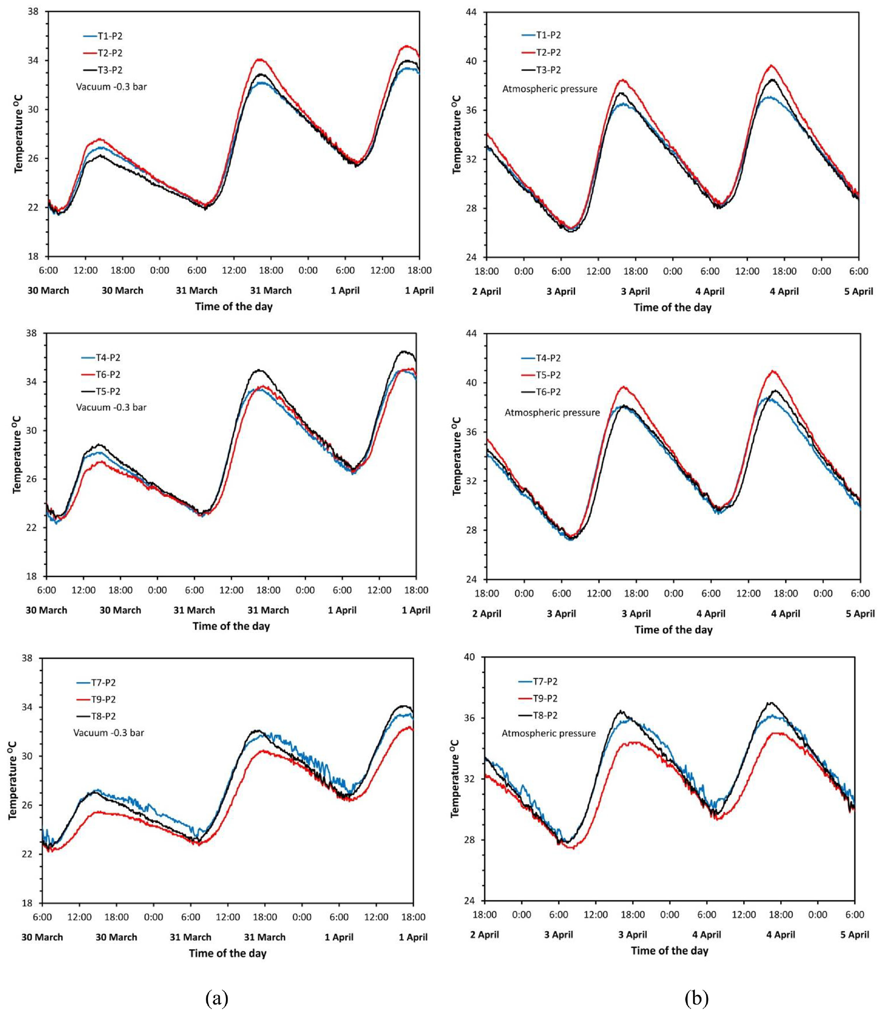
Temperature variation along the storage wall width in central plane (P2): (a) vacuum case and (b) atmospheric case.

Temperature variation along the storage wall height in central plane (P2): (a) vacuum case and (b) atmospheric case.
Numerical results and computer code validation
The measured values of the ambient temperature, the normally incident solar intensity, the wind speed, and the initial average temperature of the wall are used as input to the computer program. The computed output results of the average temperature of the wall and the exterior surface of the glazing with time are compared with the measured values for validation of the code. Figures 11 and 12 show comparisons between the measurements and predictions for the evacuated and the normal pressure cases respectively. A good agreement between the measured and predicted results for both wall average temperature and glass outer temperature is observed. This clearly shows that the developed numerical model simulates the actual behavior of the experimental model satisfactorily. Thus, the code can reliably be used to further investigate the performance of the system under different air gap vacuum pressures.

Comparison between numerical results and experimental measured data for vacuum case.

Comparison between numerical results and experimental measured data for atmospheric case.
The effect of air gap evacuation
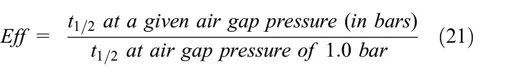
The thermal performance of a Trombe wall system is affected by the heat loss from the wall to the surroundings through the air gap and glazing. In the following numerical tests, the effect of reducing the pressure in the air gap on the heat loss is studied. A criterion is defined and used to compare the effectiveness of the isolated Trombe wall at different air gap vacuum pressures relative to non-vacuumed air gap. The time during which a system preserves its stored heat is taken as a key measure of the effectiveness and for comparing its performance. The longer the time an isolated Trombe system preserves its heat energy the better is its performance. For this purpose, the system considered above is assumed to be perfectly insulated at all its sides except the glazing side through which heat is lost to the surroundings. The surrounding temperature is assumed to be kept constant at 0°C and a heat transfer coefficient between the glazing and the surrounding air of 25 W/m2 °C, accounting for both convective and radiation heat transfer, is assumed. The system initially is heated to a certain energy level by assuming an initial temperature and then left to lose its heat through the air gap and glazing to the surroundings. Four different initial states of the stored energy, relative to 0°C, with the air gap being under normal atmospheric absolute pressure of 1.0 bar are considered first. Figure 13 shows the plots for the variation of the stored energy (or temperature) and the lost energy (or temperature) with time for all the four initial states. The time at which the curves of the available energy and the lost energy intersect is the time taken by the system to lose 50% of its initial stored energy. This time, denoted here as t1/2, at air gap absolute pressure of 1.0 bar is taken as the base line for comparing the effectiveness of the system when the air gap pressure is reduced. Thus, the effectiveness of the system is defined as
Stored energy and temperature variation with time for different initial states at air gap pressure of 1.0 bar.
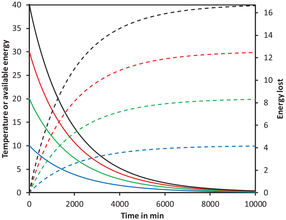
It can be noted that t1/2 values for all the four different initial temperatures are almost the same with air gap pressure being kept constant at 1.0 bar. However, for comparing the effect of reduced air gap pressure the initial state of energy is kept the same for all the numerical tests that follow. Next, numerical tests are conducted at air gap pressures of 0.5, 0.1, and 0.01 bar in addition to air gap pressure of 1.0 bar. Figure 14 shows the plots of the variation of the available energy and the lost energy normalized values, E+, against normalized time

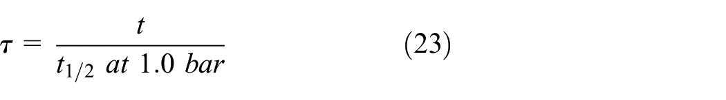

Variation of normalized available and lost energy with normalized time. Solid lines represent available energy and dashed lines represent lost energy.
According to the above normalizations and definition of the effectiveness, Eff can be directly read from the normalized plots as
Table 2 and Figure 15 show the values of effectiveness obtained against the air gap pressure. It can be seen that reducing the pressure to value of 0.1 bar, the increase in Eff is about 20%. However, further reduction beyond 0.1 bar is less effective where only 2.4% increase in Eff value is obtained by reducing the pressure from 0.1 to 0.01 bar. This behavior can be explained by considering the values of the thermal diffusivity of air
System performance at different air gap pressures.

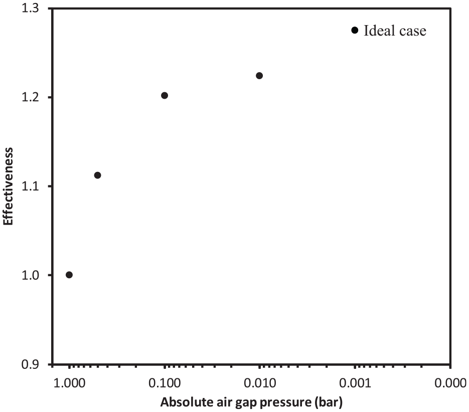
Variation of effectiveness with air gap vacuum pressure.
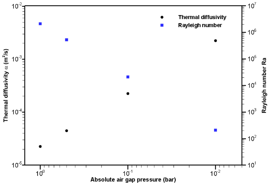
Variation of thermal diffusivity and Rayleigh number with air gap vacuum pressure.
An ideal case can be investigated numerically, that is by suppressing both convection and conduction parts of the energy equation for the fluid part of the system, that is, air in the air gap plays no role in transferring heat. The case resembles fully vacuumed air gap. Then heat exchange between the walls of the air gap takes place by radiation only. The effectiveness Eff obtained in this case further increases by about 5% compared to its value at 0.01 bar. In Figure 15 this point is shown as an ideal case and plotted against an assumed fictitious value of pressure of 0.001 bar.
In order to gain a better understanding of the factors responsible for minimizing heat losses through vacuuming of the air gap, the temperature distribution and velocity vectors are presented over the course of three different time intervals at various pressure levels. Specifically, the results are showed for conditions at 5, 10, and 25 h following the end of heat gain and rising the temperature to 40°C at pressures of 1, 0.5, 0.1, and 0.01 bar, respectively. Upon examining Figure 17, it is apparent that at time = 5 h, an increase in vacuum pressure results in a greater temperature difference between the two sides of the gap, indicating a decrease in heat transfer from the storage wall to the glass through the air gap. Notably, this trend is observed at all the other time intervals depicted in the figure as well. To investigate fluid movement with variations in pressure, one can track the velocity vector in a similar manner. When comparing the velocity vector at a pressure of 0.5 bar to that observed under normal pressure conditions, it can be observed that a thin layer forms on the wall with a reduced velocity. This phenomenon is a direct result of the pressure reduction. Upon further reducing the pressure to 0.1 bar, the thickness of this layer increases, which is reflected in the temperature difference and consequent decrease in heat transfer.

Velocity vector and temperature distribution in the Trombe wall at different times for initial state of 40°C.
When the pressure is further reduced to 0.01 bar, the layer grows thicker, impeding fluid movement and negatively affecting heat transfer. This clarifies the drop in heat losses in Figure 14 as pressure decreases.
Conclusions
The main goal of this work is to investigate whether partial evacuation of the air gap improves the thermal performance of a Trombe wall system or not. To accomplish this goal an experimental small scale isolated Trombe wall model has been constructed. The model is operated under a moderately vacuumed air gap at −0.3 bar gage and under a normal atmospheric pressure. Results of the measurements are used to validate a computer code developed for testing the performance of the system under the same ambient conditions but different air gap vacuum pressures. A criterion is devised for assessing the effectiveness of a vacuumed system relative to a non-vacuumed one. The criterion is based on the time duration that a system can preserve its stored thermal energy. Using the code, numerical experiments are conducted at absolute vacuum pressures of 0.5, 0.1, and 0.01 bars as well as 1.0 bar. In addition, an ideal case resembling fully vacuumed air gap is studied. Results show that partial evacuation of the air gap to 0.1 bar significantly increases the effectiveness of the system by more than 20%. Further reduction of the pressure to 0.01 bar increases the effectiveness only 2.2%. Reduction of the pressure to the infeasible full vacuum case increases the effectiveness further by only 5%. In conclusion, partial evacuation of the air gap to 0.1 bar is the most reasonable and effective condition for improving the thermal performance of the studied model of Trombe wall system.
Footnotes
Appendix
Notation

| d | Diameter (m) |
| g | Gravitational acceleration (m s−2) |
| h | Convection heat transfer coefficient (W m−2 °C−1) |
| k | Thermal conductivity (W m °C−1) |
| Kn | Knudsen number |
| L | Distance (m) |
| p | Pressure (Pa) |
| Pr | Prandtl number |
| q | Heat transfer rate (W) |
| Ra | Rayleigh number |
| T | Temperature (°C) |
| t | Time (s) |
| u,v | Velocity in the x and direction (m s−1) |
| V | Local mean velocity (m s−1) |
| x,y | Cartesian coordinates (m) |
| Greek letters | |
| β | Thermal expansion coefficient (k−1) |
| λ | Mean free path length (m) |
| µ | Viscosity (Pa s) |
| ν | Kinematic viscosity (m2 s−1) |
| ρ | Density (kg m−3) |
| Subscripts | |
| eff | Effective |
| g | Glass |
| rad | Radiation |
| t | Turbulent |
| T | Temperature |
| V | Velocity |
Handling Editor: Chenhui Liang
Declaration of conflicting interests
The author(s) declared no potential conflicts of interest with respect to the research, authorship, and/or publication of this article.
Funding
The author(s) received no financial support for the research, authorship, and/or publication of this article.