
Abstract
Multi-dimensional vibration isolation platforms often use parallel mechanisms to achieve multi-dimensional vibration isolation control. However, due to the high stiffness of the parallel mechanism, its own natural frequency is high, and it has good performance when applied to high-frequency vibration isolation, but it is hard to achieve low-frequency vibration isolation. This paper aims at the problem that the actual polishing and grinding equipment is often subjected to axial and circumferential low-frequency disturbances during operation, a novel C/2-(2-RRR) RR two-degree-of-freedom (2-DOF) translational-rotation low-frequency vibration isolation platform is proposed based on the singular configuration of planar 2-RRR mechanism. The coupling dynamic model of the vibration isolation platform is established, and the amplitude-frequency curve and force transmissibility curve are analyzed. The simulation analysis and prototype experiment are carried out by using the independent external excitation in both translational and rotational directions, and the corresponding linear system is compared to verify the effectiveness of the low-frequency vibration isolation of the two-degree-of-freedom vibration isolation platform.
Keywords
Introduction
During polishing, grinding and welding machining, many harmful multi-dimensional low-frequency (0.1–10 Hz) vibrations occurred due to the fluctuations of large-scale equipment nearby, which generated vibrations of large acceleration and amplitude, leading to the decreased fabrication precision, the dramatic reduction in service life, and even the damage of equipment. 1 In order to minimize the detrimental effects of the nearby environment on the machining process, it is necessary to research the multi-dimensional low-frequency vibration isolation method. Nonlinear vibration isolation mechanism is often applied to solve the problem of low-frequency vibration.2,3 The nonlinear vibration isolation mechanism is constructed by using multiple elastic damping elements to adjust the geometric relationship between them, so that it possesses the nonlinear stiffness characteristics of high static stiffness and low dynamic stiffness, which can satisfy the requirements of low natural frequency and high bearing capacity at the same time, and attain low-frequency vibration isolation. When it vibrates near the working point, the dynamic stiffness is equal to or near to 0, which is also called QZS vibration isolation mechanism.4,5
The QZS vibration isolation mechanism can also be expressed as a positive stiffness elastic element and a negative stiffness mechanism in parallel. The negative stiffness mechanism is used for stiffness correction, reducing the stiffness of the distal platform of the vibration isolation system and reducing the natural frequency at the same load capacity.6,7 Domestic and foreign scholars first conducted in-depth research on the single-degree-of-freedom quasi-zero-stiffness vibration isolation mechanism, Carrella et al.8,9 first proposed the most classical three-spring nonlinear vibration isolation mechanism. A new quasi-zero-stiffness vibration isolation mechanism composed of three springs is constructed by using two inclined springs to provide negative stiffness, and its transmission law and vibration isolation performance are explored. Kovacic et al. 10 solved the problem that the system dynamic stiffness changed sharply after deviating from the equilibrium position by replacing a linear spring with a pre-compression nonlinear spring. Xu et al. 11 obtained a new QZS vibration isolation system adaptable to various loads by using magnetic springs instead of their mechanical counterparts. Zhou et al. 12 proposed a cam-roller-spring mechanism, demonstrating that regardless of the excitation amplitude, the peak transmission rate and the initial frequency of isolators will not exceed that of linear counterparts. Kim et al. 13 proposed a quasi-zero-stiffness isolator consisting of a vertical spring with preload and eight transverse leaf springs with nonlinear buckling characteristics. It has constant stiffness and damping and can be used for ultra-precision measurement sensors. Dalela et al. 14 designed a single DOF vibration isolation system in the vertical direction by adopting the bistable chord beam as the negative stiffness mechanism, instead of the nonlinear diagonal spring. In addition, there are also negative stiffness mechanisms designed in combination with Euler buckling beams,11,15 air springs,16,17 bionic structures,18–20 and composite structures,21–23 which greatly increase the types of QZS isolators and make them truly applied to social life.
From the above, the single-DOF QZS vibration isolation mechanism has rich research results and has a good low-frequency vibration isolation effect. However, with the extensive application of high-end precision equipment in complex dynamic environments, multi-dimensional low-frequency vibration isolation research has gradually become the focus of attention, and it is still in the initial stage of research. The common design method of the multi-dimensional vibration isolation platform is to install the nonlinear vibration isolator as the driving element on each branch chain of the parallel mechanism to realize the multi-dimensional vibration isolation.24,25 Li et al. 26 designed a 5-DOF hybrid manipulator based on a PM 3-UPS for the vibration isolation in the manufacturing system, which can isolate multi-dimensional vibration and directly adjust the system to a normal working pose. A vibration isolation in three translational directions were resolved, 27 which applied symmetrical scissors mechanism to horizontal directions and traditional spring-mass-damper structure to vertical direction. Zhou et al. 28 built the pyramidal 3-QZS pillar vibration isolator by putting single DOF QZS vibration isolator with magnetic rings in each DOF. Zhang et al. 29 proposed using a torsional-translational quasi-rigid vibration isolator with a convex ball-roller mechanism to attenuate torsional and translational vibration along the shafting simultaneously. Furthermore, Li et al. 30 designed a vibration isolator composed of more than three non-collinear three-dimensional QZS fulcrums. Tang et al. 31 installed QZS vibration isolators on each branch of the Stewart mechanism to achieve a 6-DOF micro-vibration isolation platform.
However, due to the high stiffness of its internal parallel mechanism, the multi-dimensional vibration isolation platform constructed by the above method has a high natural frequency, which leads to poor low-frequency vibration isolation ability, and it is difficult to achieve multi-dimensional low-frequency vibration isolation in complex environments. Considering that the dynamic stiffness distribution at the singular configuration of the parallel mechanism often has “zero” stiffness characteristics, which meets the requirements of QZS low-frequency vibration isolation. The dynamic instability characteristics at the singularity of the mechanism, especially the dynamic characteristics such as bifurcation and jump, are also consistent with the jump characteristics of nonlinear vibration isolation dynamics, which is very helpful to expand the vibration isolation bandwidth, reduce the vibration isolation transmissibility, and realize low-frequency vibration isolation. Therefore, based on the singular configuration of the planar 2-RRR parallel mechanism and the combination of linear spring and torsional spring, a novel C/2-(2-RRR)RR two-degree-of-freedom translation-rotation low-frequency vibration isolation platform is proposed in this paper, which can effectively suppress the axial and circumferential low-frequency disturbance of polishing equipment.
The paper is structured as follows: Section 2 designs the overall structure and working principle of the vibration isolation platform, analyzes the kinematics and statics characteristics of the vibration isolation platform, obtains the QZS condition, studies its force-displacement and stiffness-displacement relationship, and verifies the effectiveness of its QZS characteristics. In Section 3 the coupling dynamic model is established, and its amplitude-frequency curve and force transmissibility curve are analyzed. Comparing with the linear vibration isolation system, the effectiveness of low-frequency vibration isolation in the translational direction and the rotational direction is theoretically verified. In Section 4 the independent excitation in both translational and rotational directions is used as the external excitation input, and the simulation analysis and prototype experiment are carried out to verify the correctness of the theoretical analysis of the low-frequency vibration isolation platform and the effectiveness of the actual low-frequency vibration isolation.
Static characteristic analysis of two-DOF low-frequency vibration isolation platform
Overall structure design of vibration isolation platform
A novel two-degree-of-freedom C/2-(2-RRR)RR translational-rotational quasi-zero-stiffness vibration isolation platform is proposed according to the design idea of quasi-zero-stiffness isolators constructed by positive and negative stiffness flexible components in parallel. The application scenario and appearance optimization model of the vibration isolation platform are shown in Figure 1. Based on the negative stiffness output of the planar 2-RRR parallel mechanism at the singularity, combined with the positive stiffness spring, a two-degree-of-freedom QZS vibration isolation platform is constructed, which can efficiently suppress the axial and circumferential low-frequency disturbances of polishing, cutting, drilling, and other medical equipment.

Three-dimensional model of C/2-(2-RRR)RR vibration isolation platform: (a) applications and (b) physical model.
The structure of the vibration isolation platform is shown in Figure 2. Including the workbench, center platform, connecting rod, support column, base, torsion spring group, and planar 2-RRR parallel mechanism. The central platform is located in the center position of the vibration isolation platform, and slides on the support column through the linear bearing. The lower end is connected with the positive stiffness spring, and the upper end is connected with the worktable through the shaft hole matching. Polishing and polishing equipment that needs to isolate low-frequency vibration is placed on the workbench. The two sides of the central platform are hinged by pin shaft and connecting rod respectively to form a rotating pair. The support column is fixed on the base by the horizontal support seat, and the pressure spring sleeve is outside the support column, which is connected with the base and the central platform to play the role of supporting the platform and buffering the low-frequency disturbance in the vertical direction. The pressure spring has a preload value according to the quality of the actual isolated polishing and grinding equipment, which provides positive stiffness for the vertical direction of the vibration isolator.
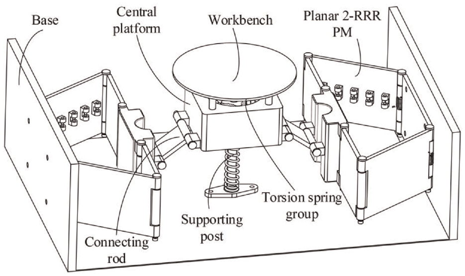
Overall structure diagram of C/2(2-RRR)RR vibration isolation platform.
The central platform is bordered by two planar 2-RRR parallel mechanisms in a symmetrical manner. The connecting rod is hinged with the end connecting block of the planar 2-RRR parallel mechanism through the pin. In the event that the connecting block aligns perfectly with the two adjacent first plates, meaning that the planar 2-RRR parallel mechanism is positioned in a singular configuration, and when combined with the torsion spring and preloading value, it can yield a negative stiffness in both the axial and circumferential directions for the vibration isolator.
The positive stiffness buffer device of the vibration isolation platform is shown in Figure 3(a) and (b), including the torsion spring group and the pressure spring, which provide positive stiffness for the vibration isolation platform along the vertical axial direction of the support column and the circumferential direction of the support column. The torsion spring group includes multiple springs and sliders set on the round table, and pulleys set in the eccentric orbit. The central platform is provided with a central groove to accommodate the round table, and the central platform is provided with an eccentric track near the side edge. The pulley is connected to the slider through the rod and connected with the eccentric track.

Vibration isolation platform positive and negative stiffness buffer device: (a) axonometric diagram of the positive stiffness device, (b) profile of the positive stiffness device, and (c) structure diagram of negative stiffness device.
When the vibration isolation platform is subjected to circumferential disturbance, the truncated cone does not rotate, and the eccentric orbit moves with the rotation of the central platform, resulting in the pulley of the slider in contact with it sliding in the eccentric orbit. Due to the coaxial arrangement of the column and the supporting column, the center of the eccentric orbit deviates from the central arrangement of the column, so it is different from the center of the column. Therefore, when the eccentric orbit rotates, the linear contact position between the pulley and the eccentric orbit will change. That is, the center position of the pulley relative to the round table changes, which drives the slider to move forward and backward and then drives the spring connected to the slider to achieve tensile or compressive motion, providing torsional positive stiffness.
The vibration isolation platform’s negative stiffness buffer device is depicted in Figure 3(c). The connecting rod is hinged with the connecting block in the planar 2-RRR parallel mechanism. The central platform propels the connecting rod, and the connecting rod propels the connecting block once more, resulting in the planar 2-RRR parallel mechanism moving in tandem with the central platform. A torsion spring is positioned in the middle of the shaft connecting the second plate and the bottom plate, and a row of torsion spring fixings is arranged on the inner wall of the second plate, so that different preloading values can be set for the torsion spring according to the actual situation. When the connecting block is aligned with the two first plates on both sides, the parallel mechanism is situated in the singular configuration, exhibiting minimal stiffness values in both the vertical axial and circumferential directions, in conjunction with the torsion spring; thus, the negative stiffness is produced at the connecting block.
The motion diagram of the two-degree-of-freedom QZS vibration isolation platform is shown in Figure 4. The vertical spring stiffness is

Two-DOF vibration isolation platform mechanism diagram.
Working principle of vibration isolation platform
The initial position is shown in Figure 2. The polishing and grinding equipment are placed on the working table. The center of the polishing and grinding equipment is preferably collinear with the support column, and the vibration isolation effect is better. According to the quality of the polishing and grinding equipment, the preloading values of the pressure spring and the torsion spring are set. The spherical top of the slider in the torsion spring group is in point-to-point contact with the top center of the cylindrical cam, and the connecting block is in the same straight line with the two first plates.
The variation of the motion of the vibrational isolation platform is shown in Figure 5 when the quasi-zero rigidity vibrational isolation platform is subjected to axial low-frequency perturbations caused by the surrounding environment along the support column. The center platform moves upward, driving the connecting rod upward, and the connecting block moves forward by the horizontal tension of the connecting rod, thus driving the first and second plates inward. The torsion spring at each end of the bottom plate is subjected to the torque from the second plate, while the pressure spring is also subjected to the tension from the central platform, and the two together generate the restoring force.

The working principle of the vibration isolation platform.
When the vibration isolation platform is disturbed by a low circumferential frequency with the support column as the central axis, the movement of the vibration isolation platform caused by the surrounding environment is shown in Figure 5. The central platform rotates along the circumference of the supporting column and its internal eccentricity track moves with it, causing the pulley to drive the slide forward and back, thus driving the internal torsion spring to tensile or compressive motion and providing torsional positive stiffness. The connecting rod rotates with the central platform, causing the connecting block to rotate, thus driving the rotation of the first and second plates. The torsion springs at both ends of the bottom plate are affected by torque from the second plate, providing negative torsional stiffness. The combination of positive and negative stiffness constitutes a QZS torsional vibration isolation platform.
When the vibration isolation platform is disturbed in axial and circumferential disturbances, the central platform shifts vertically along the axial direction of the supporting column and rotates along the circumferential direction of the supporting column. The connecting rod moves with the central platform, driving the planar 2-RRR parallel mechanism to change its motion. When disturbed separately, the principle of the recovery force is the same as mentioned above.
Statics model establishment of vibration isolation platform
Kinematic analysis of negative stiffness mechanism
The negative stiffness mechanism is symmetrical; therefore, only half of the designed mechanism model is used to calculate the static characteristics of the vibration isolation system. As shown in Figure 6, the black wire frame outlines the initial mechanism position. The preload of the z-positive stiffness spring

Motion analysis diagram of negative stiffness mechanism.
The actuation force has no effect on the translation of y-direction and rotation along the z-axis. The torsion spring provides preloads
When the mechanism is deformed by external excitation forces and torques, the position of the negative stiffness mechanism is shown in Figure 6 (red wireframe). The absolute displacement of load movement is defined as z, and the absolute rotation angle is α. With point

Where the length of is
Now, equation (1) can be converted into the expression:
Where,

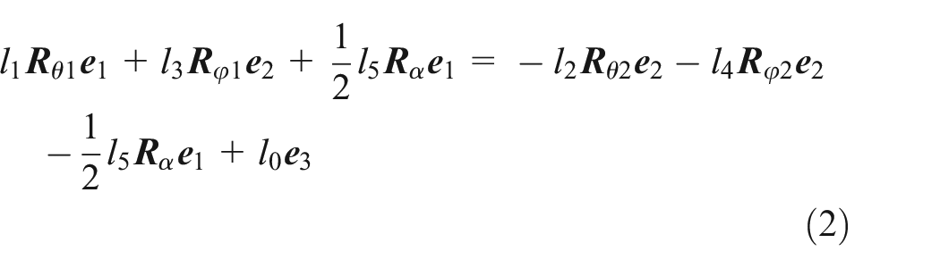
Based on the closed loop vector expressed by

Substitute equation (3) into equation (2). The relationship between the output coordinate

It is known that the distance change of point

The relationship between input
By substituting equation (5) into equation (4), it can be concluded that when the QZS vibration isolation platform is subjected to axial and circumferential low-frequency disturbances, The relationship between the motion variation

Static analysis of vibration isolation platform
The kinematic analysis in the previous section illustrates the geometric correlation between each rod of the negative stiffness mechanism and the load platform, while the force analysis is depicted in Figure 7.

Force analysis of vibration isolation platform.
At the static equilibrium position, the initial torsional spring angle is

Links

Since the connecting rod projection in the y-direction is always perpendicular to the moving platform

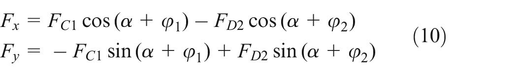
Force


Equations (11) and (12) show that
The positive stiffness spring preload is
where,
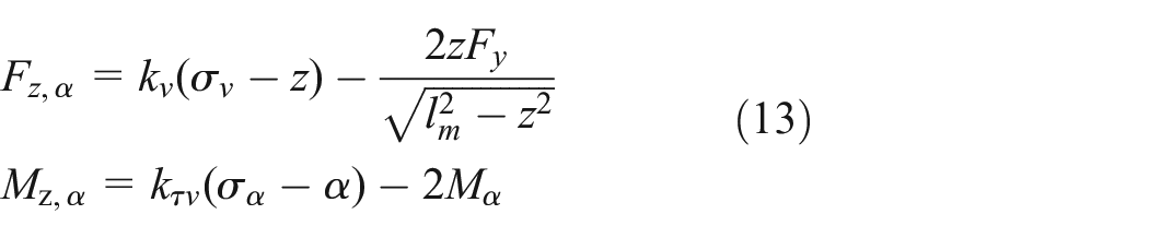
Therefore, the force and torque stiffness of the overall vibration isolation system is the first-order partial derivatives of


Force and stiffness characteristics of vibration isolation platform
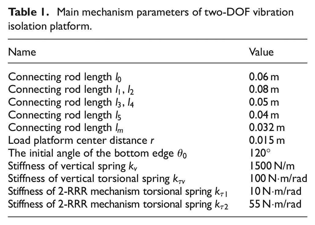
The vibration isolator is designed according to the size of load and the compactness of the overall structure of the isolator. Inside the isolator workspace, when
Main mechanism parameters of two-DOF vibration isolation platform.

Two-dimensional stiffness curve of vibration isolation platform: (a) translational direction and (b) rotational direction.
Figure 9 depicts the force-displacement and stiffness-displacement curves of the vibration isolation system for the constant rotation angle

Force and stiffness characteristics of a vibration isolation platform under translational disturbance only: (a) force displacement curve and (b) rigidity displacement curve.
Regarding the stiffness-displacement curve, when
Similarly, Figure 10 depicts the torque-displacement and stiffness-displacement curves of the vibration isolation system along the z-axis rotation direction for the constant translational displacement

Force and stiffness characteristics of vibration isolation platform under rotation disturbance only: (a) torque displacement curve and (b) rigidity displacement curve.
Dynamic analysis of vibration isolation platform
Analysis of amplitude-frequency curve of vibration isolation platform
In this section, the dynamic behavior of a coupled translational-rotational QZS system with 2-DOF is studied. It is assumed that the isolation load is located in the loading platform center of mass and that the isolation system is in equilibrium without any external excitation. The payload mass and the moment of inertia around the platform centroid are


where
By introducing dimensionless symbols, we obtain:

Equations (16) and (17) can be rewritten as:


The harmonic balance method was used to solve the approximate system response. Because in the system response, the frequency component with the same frequency as the external excitation frequency is the main part, with the extension of vibration excitation time, the system response frequency will eventually become identical to the external excitation frequency. Therefore, regardless of the value of


Where

The equation for

where
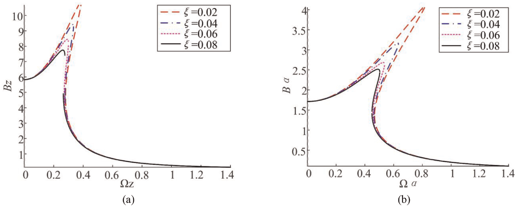
As shown in Figures 11(a) and 12(a), the two-dimensional amplitude-frequency curves of the vertical translational direction and the rotational direction of the response of the two-degree-of-freedom QZS system are shown respectively. Figures 11(b) and 12(b) are the corresponding two-dimensional amplitude-frequency curve profiles, which are used to more clearly analyze the influence of the amplitude of the vibration isolation system on the frequency change during the translation process and the rotation process and the coupling effect between the two direction variables.

Amplitude-frequency curve of the translational direction of the vibration isolation platform: (a) two-dimensional translational direction amplitude-frequency curve and (b) z-direction amplitude-frequency curve with different

Amplitude-frequency curve of the rotation direction of the vibration isolation platform: (a) two-dimensional rotation direction amplitude-frequency curve and (b)
From Figures 11(b) and 12(b), it can be seen that the relative vibration isolation system response amplitude displays a jump phenomenon with the increase in external excitation frequency. The jumping phenomenon means that the vibration isolation system has a jump-up frequency and jump-down frequency. When the external frequency increases gradually from 0, the system response amplitude will also increase gradually. The system response amplitude is the largest upon entering the resonant frequency. If the frequency is further increased the system will reach the jump-down frequency and the system response amplitude will decay rapidly. Further increase in the frequency will cause slight response amplitude fluctuations achieving the vibration isolation effect.
For the jump frequency, the frequency is gradually reduced from a relatively large frequency. When the frequency reaches the resonance frequency of the system, the response amplitude increases rapidly. At this time, the object resonates with the external excitation, thus causing damage to the object itself. Up-jump frequency and down-jump frequency are unique characteristics of nonlinear vibration isolation system, but linear system does not have. It is precisely because of the existence of the amplitude-frequency curve jump phenomenon that the nonlinear system has good low-frequency vibration isolation ability and realizes low-frequency vibration control.
Simultaneously, as translational or rotational motion occurs the increasing coupling amount in the other direction reduces the resonance peak, but the initial vibration isolation frequency is greatly increased. The vibration isolation bandwidth becomes narrow which is not conducive to vibration isolation.
Performance analysis of force transfer rate
The force transfer rate is defined as the ratio between the force transferred to the base and the excitation force acting on the load-moving platform. As such, it can be used to measure and evaluate the performance of a vibration isolation system under low-frequency vibration.
As shown in Figure 13 with the increase of damping ratio, the resonance peak of the isolated object gradually decreases, the jump phenomenon is weakened, and the initial frequency of vibration isolation decreases. The amplitude jump phenomenon is a typical characteristic of a nonlinear vibration isolation systems. The jump phenomenon does not exist in linear systems.
Amplitude-frequency curves of different damping ratios: (a) translation direction and (b) rotation direction.
The force and moment of the external disturbance excitation transmitted to the load platform after passing through the two-degree-of-freedom quasi-zero-stiffness isolator are:

The force transfer rate is expressed as:

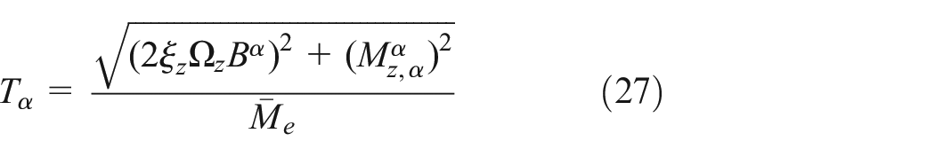
Figure 14 shows the force and moment transfer rate curves of the vibration isolation system in vertical translational and rotational directions for predefined damping and external excitation conditions. The black line represents a linear vibration isolation system. It can be seen that, compared to the linear vibration isolation system, the proposed vibration isolation system has a lower resonance peak, given that the conditions are equal.

Force and torque transmissibility of vibration isolation platform.
When the frequency ratio is greater than
The force transfer rate curves for various damping ratios in the translational direction are given in Figure 15(a). With the increase of the damping ratio, the resonance peak of the vibration isolation system gradually decreases, significantly weakening the jump phenomenon. When the damping ratio is large enough, the jump phenomenon can be eliminated. However, with the increase in frequency, especially following the high frequency, the damping ratio increase will increase the force transfer rate, which is not conducive to high-frequency vibration isolation. At the same time, it can be seen that, compared to the linear vibration isolation system, the new QZS vibration isolation system has a larger vibration isolation bandwidth and smaller resonance peak. In brief, its performance in low-frequency vibration isolation is superior than that of the linear system.

Transfer rates in the translational direction of QZS vibration isolation platform: (a) transmissibility curves for various damping ratios and (b) transmissibility curves for various external excitations.
The force transfer rate curve obtained by changing the external excitation force magnitude is shown in Figure 15(b). With the gradual decrease in the excitation force amplitude, the force transfer rate resonance peak of the vibration isolation system decreases. Simultaneously, the resonance peak moves toward the low-frequency direction, and the initial vibration isolation frequency decreases. This broadens the effective vibration isolation frequency band and is beneficial to low-frequency vibration isolation.
Figure 16(a) shows torque transfer rate curves with different damping ratios in the rotation directions, while Figure 16(b) shows torque transfer rate curves under different external torque excitations when rotating around the z-axis. From the diagram, it is evident that the influence of the damping ratio and external excitation on torque transfer rate when the vibration isolation system is disturbed by external torque excitation is the same as for the external force excitation, so it is not repeated.

Transfer rates in the rotation direction of QZS vibration isolation platform: (a) transmissibility curves for various damping ratios and (b) transmissibility curves for various external excitations.
Simulation analysis and prototype experiment
Simulation analysis
A random multi-frequency harmonic excitation was used as input, and white noise was added. Force acceleration and angle input were used as evaluation criteria for the vibration isolation ability in the translational and rotational directions. The Runge-Kutta numerical analysis was carried out to verify the theoretical results.
The multi-frequency excitation input in the translational direction is given:

For a nonlinear system, it is assumed to be smoothly excited by the base acceleration, and the spectral type is a flat spectrum in the band 0–10 Hz. The PSD of the vertical direction is 20 dB, the PSD of the rotation direction is 10 dB, and the calculation duration is t = 10 s. The vibration isolation effect of the isolator was quantitatively analyzed through the time-domain acceleration curve, and the excellent vibration isolation performance of the isolator was visually observed by drawing the PSD curve from the perspective of energy.
The outputs of the linear and QZS systems can be obtained through the Runge-Kutta simulation analysis, as shown in Figure 17, The peak acceleration of the linear system is 7.39

Numerical simulation results of translational direction: (a) time-domain comparison diagram and (b) power spectral density comparison diagram.
The rotational direction multi-frequency excitation input is given:

The numerical simulation results are shown in Figure 18. The average peak value of the output angle of the linear system is 4.58
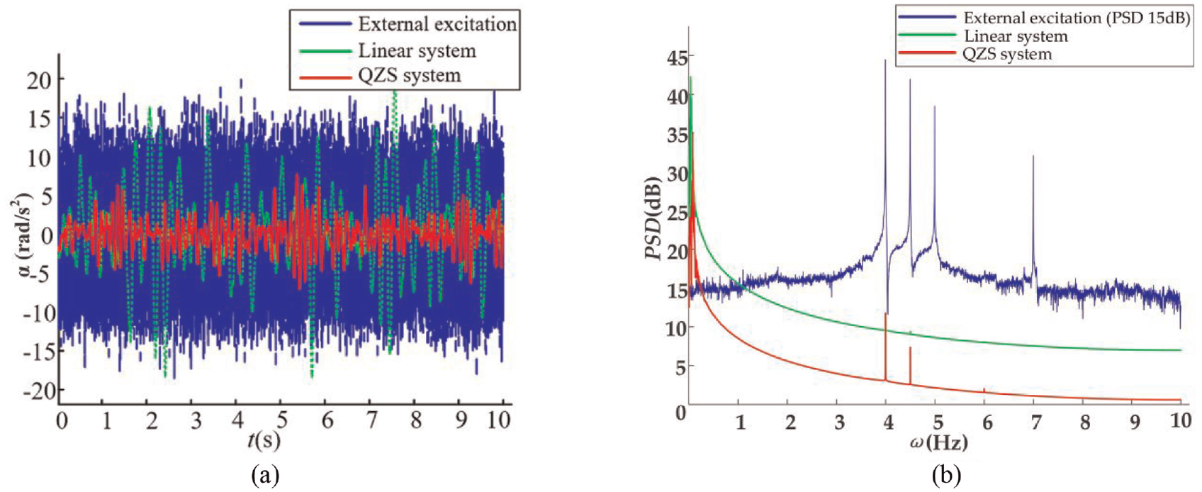
Numerical simulation results of rotation direction: (a) time-domain comparison diagram and (b) power spectral comparison density diagram.
Prototype experiment
From the theoretical analysis described above, it can be seen that compared with the linear vibration isolation system, the quasi-zero-stiffness vibration isolation system constructed by the singularity of the mechanism has a lower initial vibration isolation frequency, a smaller resonance peak and a wider vibration isolation bandwidth, which can better achieve low-frequency disturbance control. However, the experiment is the ultimate basis for testing the correctness of the theory. Therefore, it is necessary to carry out the disturbance experiment test of the quasi-zero-stiffness vibration isolation system. The physical diagram of the prototype is shown in Figure 19.

Prototype of vibration isolation platform.
The experimental system is mainly composed of four parts. disturbance input unit, vibration isolation system, measurement unit and host computer data processing unit, as shown in Figure 20. The perturbation input unit uses the existing six-degree-of-freedom seismic simulation platform in the laboratory, which can realize vertical movement and axial disturbance movement. By setting the internal operation program, the sinusoidal constant frequency disturbance input and random disturbance input can be realized. The measurement unit is mainly composed of angle sensor, displacement sensor and data acquisition module. Finally, the collected data is transmitted to the host computer for data processing.

The experimental system of vibration isolation platform was built.
Sinusoidal constant frequency experiment
The main purpose of the fixed-frequency disturbance experiment is to test the low-frequency vibration isolation capability of the quasi-zero-stiffness vibration isolation system under the external defined-frequency input disturbance. Because the designed quasi-zero-stiffness vibration isolation platform is a translational-rotation two-degree-of-freedom, experiments in two directions are required. Firstly, the vertical translational vibration isolation experiment is carried out, and the external input disturbance is set to
When the external input disturbances are
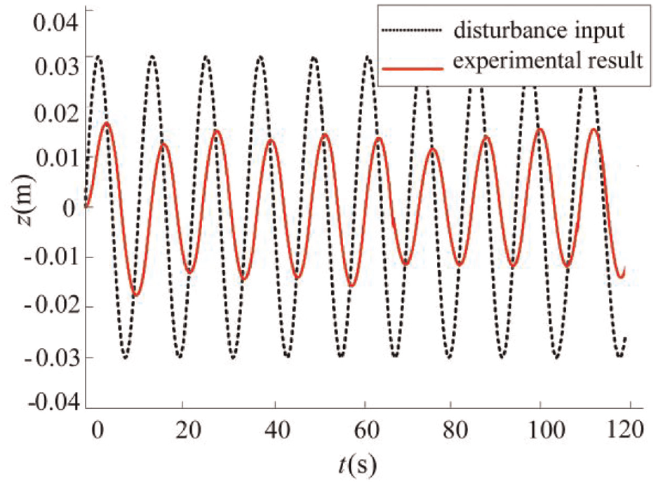
The input disturbance is

The input disturbance is
Then the vibration isolation experiment in the torsional direction is carried out. The input excitation is set to, where the disturbance amplitude is, and the frequency values are 0.5 and 2 Hz. The experimental results are shown in Figures 23 and 24. It can be seen from the experimental results that the quasi-zero-stiffness isolator has the ability to attenuate the disturbance in the torsional direction, and the attenuation effect is about 70%. As the amplitude of the external disturbance decreases and the frequency increases, the attenuation effect will gradually increase.
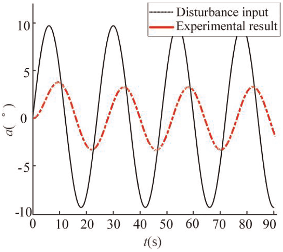
The input disturbance is

The input disturbance is
Random perturbation experiment
The disturbance input unit is set as a random disturbance mode, and the experimental data are shown in Figure 25. It can be seen from the disturbance experimental results that the quasi-zero-stiffness vibration isolation mechanism designed in this paper also has an attenuation effect on random disturbances.

Random disturbance experiment of vibration isolation platform: (a) vertical translational direction and (b) rotation direction.
The results of sinusoidal constant frequency experiment and random disturbance experiment show that the two-DOF QZS vibration isolation mechanism designed in this paper has good vibration isolation effect against low-frequency disturbance. For low-frequency translational disturbance in the vertical direction, the amplitude of the disturbance can be attenuated by about 60% on average, and for low-frequency torsional disturbance in the rotation direction with the vertical direction as the axis, the amplitude of the disturbance can be attenuated by about 50% on average, and the conversion component is not required, and the low-frequency disturbance in both directions can be isolated at the same time, which verifies the correctness of the theoretical analysis.
Conclusions
The research of multi-dimensional low-frequency vibration isolation platform is always a difficult point in the field of low-frequency vibration isolation. Parallel mechanism is often used to design multi-dimensional vibration isolation platform because of its multi-branch chain, multi-dimensional motion and compact structure. However, due to the high stiffness of the internal parallel mechanism, the traditional multi-dimensional vibration isolation platform has poor low-frequency vibration isolation ability, which is difficult to meet the multi-dimensional low-frequency vibration isolation in complex environment. Considering that the dynamic stiffness distribution at the singular configuration of the parallel mechanism often has “zero” stiffness characteristics, it can meet the requirements of quasi-zero-stiffness low-frequency vibration isolation. Based on the singular configuration of the parallel mechanism, a multi-dimensional low-frequency vibration isolation platform with low dynamic stiffness and high bearing capacity can be designed to realize low-frequency vibration isolation. 32
In order to solve the problem that rotary polishing equipment often suffers from axial and circumferential low-frequency disturbance during operation, a low-frequency vibration isolation mechanism is designed based on the singular configuration of planar 2-RRR parallel mechanism, and a new C/2-(2-RRR)RR two-degree-of-freedom translation-rotation low-frequency vibration isolation platform is proposed. The working principle is analyzed, and the kinematic and static models are established to verify its QZS characteristics. The coupled dynamic model is established, and the amplitude-frequency response characteristics and force transmissibility characteristics of the system are analyzed. The effectiveness of its low-frequency vibration isolation is verified theoretically. Finally, the simulation analysis and prototype construction are carried out. The independent excitation in both translational and rotational directions is used as the external excitation input. The sinusoidal fixed frequency experiment and random disturbance experiment are carried out to verify the correctness of the theoretical analysis of the low-frequency vibration isolation platform and the effectiveness of the actual low-frequency vibration isolation.
Footnotes
Handling Editor: Chenhui Liang
Authors’ contributions
All authors contributed to the study conception and design. Material preparation, data collection, and analysis were performed by Shuai Wang, Dawei Xin, Lang Yu, and Qinghua Zhang. The first draft of the manuscript was written by Dawei Xin and all authors commented on previous versions of the manuscript. All authors read and approved the final manuscript.
Declaration of conflicting interests
The author(s) declared no potential conflicts of interest with respect to the research, authorship, and/or publication of this article.
Funding
The author(s) disclosed receipt of the following financial support for the research, authorship, and/or publication of this article: This research was funded by the National Natural Science Foundation, China (Grant No. 52105009), by the Project of Shenzhen Municipal Science and Technology Innovation Council (Grant No. KCXFZ20201221173202007), by the Key Scientific Research Platforms and Projects of Guangdong Regular Institutions of Higher Education, China (Grant No. 2022KCXTD033), by the Scientific Research Capacity Improvement Project of Key Developing Disciplines in Guangdong Province, China (Grant No. 2021ZDJS084), by the Guangdong Natural Science Foundation, China (Grant No. 2023A1515012103), by the Key Laboratory of Robotics and Intelligent Equipment of Guangdong Regular Institutions of Higher Education, China (Grant No. 2017KSYS009), by the Innovation Center of Robotics and Intelligent Equipment, China (Grant No. KCYCXPT2017006).
Ethics approval
Not applicable.
Consent to participate
Not applicable.
Consent for publication
Not applicable.
Availability of data and materials
The data used to support the findings of this study are included within the article.
Code availability
Not applicable.