
Abstract
A well-designed flow field is a key factor to improve the surface quality of products by removing spatter, which is often generated during the selective laser melting (SLM) process. In the present study, three typical schemes are developed for the gas flow system of large-scale SLM equipment. In this regard, the flow deviation and velocity increase indices are implemented to characterize the flow uniformity in the chamber and gas flow velocity in the clearing area. The obtained results show that the inlet size significantly improves the flow uniformity and the segmented inlet increases the flow velocity above the machining surface. More specifically, when the velocity deviation index decreases from 0.3335 to 0.1538, the corresponding velocity index increases from 10.16% to 29.83%. To improve the flow uniformity on the machining surface, the effect of the inlet flow rate on the airflow over the machining surface is investigated. The obtained results show that when the inlet flow rate reduces to 0.2 m/s, the removal spatter improves while the airflow remains uniform. The results of this study can provide a reference for the design of SLM gas flow systems.
Introduction
Selective laser melting (SLM) technology is a rising metal additive manufacturing technology, which is widely applied in diverse applications, including aerospace,1–4 medical biology,5–9 and automotive industries. 10 This technology is compatible with a variety of metals and yields high-quality mechanical components.11–15 Many scholars have worked on the quality of SLM manufactured parts. They have studied the optimization of process parameters, scanning and printing path strategy, material development and optimization of SLM to solve the defects and improve the overall performance of the parts. Different process parameters of SLM can cause changes in microstructural characteristics and thus affect the material properties. Therefore it is important to further improve the mechanical properties of the material through process optimization or post-processing. Kuo et al. 16 fabricated Sc-modified aluminum alloy by laser powder bed fusion (LPBF) to obtain superior strength and ductility of the material. According to the stress concentration effect and the Hall-Page effect, the mechanical properties of 3D printed materials vary greatly depending on the differences in defect size, shape and grain size. This study also explores the parameter-tissue-property relationships of 3D printed Sc-modified aluminum alloys from the perspective of melt pool interactions.
Relevant studies have found that the laser scanning strategy of SLM affects the temperature gradient during part molding. Its optimization can effectively reduce residual stress and warpage deformation and improve part quality. Zhang et al. 17 investigated the effect of laser scanning strategy on the organization evolution, residual stresses and mechanical properties of Al-4.2Mg-0.4Sc-0.2Zr alloy processed by LPBF. The authors used laser scanning strategies including parallel, bi-directional, island and remelting modes for comparison. They found that this resulted in good improvements in surface roughness, residual stresses and properties of the materials. However, the study did not do a specific research on the effect of SLM temperature gradient changes on material quality. In order to better solve the problems caused by temperature gradients. Kim and Hart 18 applied a power optimization procedure using spiral mode to keep the molten pool temperature stable. This spiral pattern reduces the spatial variation in temperature, while at the end of the scan, the larger area remains above the specified threshold temperature, thus ensuring smaller differences in temperature. In addition, Sehhat et al. 19 spheroidized 304 L stainless steel powder particles by a plasma spheroidization process in order to evaluate the effect of the spheroidization process on the properties of powders and parts. The researchers measured and compared the mechanical properties of parts made from received and spheroidized powders using a laser printing process. The experimental results showed that the parts made from plasma spheroidized powder had lower tensile strength but higher ductility.
However, the above optimization of process parameters needs to involve multiple experiments, which is costly and requires more time. This is not much of an improvement in solving the main problem of SLM of obtaining inconsistent part quality. In recent years, with the development of artificial intelligence techniques such as Machine Learning (ML), which utilizes simulation to achieve higher part quality, the use of smaller datasets can be used to develop and train algorithms for machine learning to predict the quality of a part by looking at it from different perspectives. Integrating ML into different stages of the L-PBF process chain, ML can be used for part design and documentation preparation before L-PBF. Then, ML algorithms can be applied for process parameter optimization and in-situ monitoring will lead to better quality control. 20 Drissi-Daoudi et al. 21 investigated state-of-the-art machine learning (ML) algorithms as on-line process monitoring to differentiate between various materials and process regimes for additive manufacturing of laser melted powders. Three conventional ML algorithms and a convolutional neural network (CNN) were selected to perform the classification task, and the results show the potential of our approach for online laser additive manufacturing process monitoring of different materials and regimes.
However, the above and previous studies have focused on the optimization of process parameters using scanning printing strategies or combined with machine learning have made great strides and achieved certain results in solving defects and improving the overall performance of parts. However, the theoretical study of simulation to address the generation of splatter during the printing process has not been given much attention. Studies show that material spattering is the most challenging problem of the selective laser melting process, and excessive deposition of material on the machining surface significantly affects the manufactured quality. 22 The gas flow system in SLM machines supplies inert gas on the machining surface to prevent oxidation of the machined part and to remove spatter and vapor fumes. Accordingly, the study of shielding gas flow is of great importance to improve the machining quality.23,24 To get high-quality parts, it is necessary to optimize the behavior of shielding gas to obtain a satisfactory performance.25–28 Therefore, numerous investigations have focused on the shielding gas in the SLM process. In this regard, Ferrar et al. 27 improved the uniformity of gas flow distribution within the cavity of the SLM250 machine and effectively eliminated spatter and vapor fumes, thereby achieving a promising performance in machined parts, reducing part porosity, and increasing compressive strength of the product. Reijonen et al. 28 showed that the improved flow uniformity increases the minimum gas flow rate over the machined surface and increases the part quality.
Further investigations reveal that a uniform flow field may not remove the material spatter completely. Recently, the deposition process of spatters has been studied extensively. Anwar and Pham 26 analyzed the spatter deposition in the SLM280 machine and found that large-sized spatters mainly deposit near the scanning area. It was also found that increasing the gas flow rate improves the transport of spatters, but does not necessarily remove all spatters. Zhang et al. 29 carried out numerical simulations on a Renishaw AM250 machine and showed that when the inlet volume flow rate increased from 250 to 500 L/min, the corresponding spatter removal rate increased by 33%. Alquaity and Yilbas 30 studied the deposition process of the spatter and found that the drag force imparted by the inert gas flow significantly affects the trajectory of the spatter. The increase in the gas flow rate expands the transmission distance of the spatter, causing more spatter to be deposited outside the machined surface.
Aiming at understanding the main factors affecting the gas flow uniformity in a chamber, Chen and Wang31,32 used computational fluid dynamics (CFD) and particle image velocimetry (PIV) techniques to investigate the flow fields generated by circular, rectangular, double-rectangular, and elliptical nozzles. It was found that among the studied cases, the highest momentum exchange and flow uniformity was achieved from elliptical nozzles. The obtained results showed that the higher the aspect ratio of the nozzle, the faster the velocity decay, the higher the diffusion and entrainment rates, and the smaller the stagnation zone. Pinghua et al. 33 applied the air supply channel into a grid structure and improved the uniformity of the wind velocity distribution in the laser scanning area and removed the unwanted fumes residue during processing. Tzeng et al. 34 studied the effects of the blowing nozzle geometry, suction channel thickness, and suction channel height on the splash removal rate and showed that the suction channel height is a key parameter to improve splash removal efficiency. Chen et al. 35 simulated the airflow in the chamber and analyzed different parameters, including the nozzle height, nozzle width, and the gas flow rate to improve the nozzle jet stability and the airflow uniformity. Wang and Chang 36 investigated the flow uniformity produced by different trapezoidal nozzle widths, suction channel widths, and nozzle-to-plane distances. Philo et al. 37 developed a discrete phase model (DPM) to simulate splashes and explore the effect of inlet design parameters on the splash. Accordingly, it was found that as the inlet radius increases, the corresponding flow uniformity and average velocity improve, and the material splash reduces significantly. Meanwhile, it was found that adjusting the inlet and outlet heights can improve the flow uniformity and increase the fluid velocity. Zhang et al. 38 performed a 3D transient simulation of the airflow and found that the Coanda effect in the downward component velocity limits the maximum spatter removal rate. Accordingly, the nozzle structure was modified to a stepped type to reduce the influence of the Coanda effect and the splash removal rate increased from 69% to 93%.
Improving the gas flow rate can remove more spatter, which is beneficial to improve the processing quality.26,29,30 However, it is necessary to ensure that the powder will not destroy the surface during the process. Consequently, the maximum velocity of the bottom gas stream in the contact with the powder is limited by the threshold velocity of the powder. Currently, most solutions to improve the flow uniformity are for a single inlet nozzle31–37 and no additional inlet nozzle is considered. Therefore, further investigations should be carried out to increase the flow uniformity in the chamber and improve the spatter removal rate. The main objective of the present study is to study the flow uniformity by an additional arrangement of inlet nozzles and analyze the splash removal effect by adjusting the gas flow rate. To this end, a segmented nozzle structure is proposed to increase the gas flow rate while ensuring that the powder on the machined surface is not damaged.
In this article, the internal wind field of a laser selective melting chamber is simulated using CFD techniques to achieve a uniform flow within the chamber. It is intended to achieve a homogeneous flow field and design an optimization scheme based on the numerical analysis to study the effect of the input flow on the flow homogeneity of the chamber, velocity homogeneity of the bottom surface, and airflow characteristics.
Methodology
Figure 1 shows the configuration of the established model. The model mainly consists of a cavity, air inlet, and air outlet parts. The dimensions of the cavity part are 642 mm × 600 mm × 463 mm, and the air inlet and outlet are arranged on both sides of the model. In this model, inert gas is blown into the cavity, and a uniform protective airflow forms above the processing surface, which removes the fumes and splashes during processing. The atmosphere protection system with different inlet airflows is analyzed in the Fluent software. The flow field is simulated and analyzed, and the air intake mode is optimized according to the flow characteristics.

Configuration of the studied equipment.
Design of models
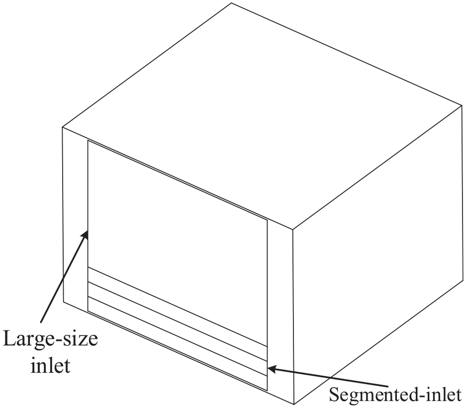
Since air inlet and air outlet can affect the flow characteristics of airflow, cleaning ability of the flow, and performance of machined parts, it is of great practical significance to study the influence of related designs on the flow field. In this regard, the equipment model is simplified according to the analysis conditions. The established simplified model consists of different air inlets, air outlets, and chambers. More specifically, three types of air inlets, including normal inlet, segmented inlet, and large-size inlet are considered in the simulations. The layout of the three air inlets is shown in Figure 2.

Layouts of different air inlets: Scheme 1: one single normal inlet at the bottom of the front face. Scheme 2: one segmented inlet arranged at the bottom of the front face. Scheme 3: one normal inlet and one large-size inlet arranged at the bottom and middle of the front face.
Numerical model
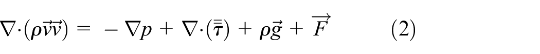
In the present study, the flow field is simulated using ANSYS Fluent software, assuming that the gas in the chamber is incompressible, the chamber is adiabatic and there is no heat exchange between the inside air and the outside environment. The transport of spatters by the inert gas flow is deemed as dilute flow. 26 The particle motion is generally governed by the lift and drag forces. In this case, one-way coupling is used. The governing equations are the conservation of mass, momentum, and energy. Moreover, it is assumed that there is no internal heat source such as lasers. The gas flow at the inlet is calculated as turbulence. Taking into account the accuracy of fluid flow calculation and the computing capacity of the computer, the standard κ-ε turbulence model is used. The continuity and momentum governing equations are as follows 39 :

where

where
Computational parameters for simulating the chamber.

Gas flow criteria
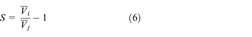
The velocity deviation index is defined in the form below to measure the degree of uniformity of the gas flow in the chamber:

where
where
Mesh generation
The three-dimensional geometric model is built and meshing of working chamber is divided by ANSYS MESH. Since the structure of working chamber is relatively simple, a structured grid is used. Large gradients near the build chamber walls were captured by using five inflation layers with a growth rate of 1.1. After the grid is divided, the grid model is imported into FLUNET for grid check and the result of check is qualified.
Independence test
Mesh independence verification was performed to study the effect of mesh resolution on the results. The characteristics of the gas flow above the machining surface are important for spatter removal, and the plane 30 mm above the machining surface was chosen as the clearing area. The velocity distribution in the clearing area was analyzed in a grid independence test. Figure 3 shows that when 1 × 10⁶ grids are considered in the simulation, the obtained results are independent of the resolution.
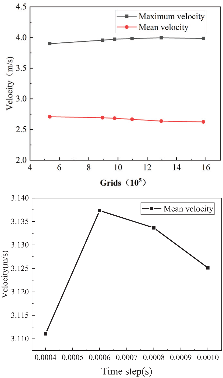
Independence analysis of the clearing area.
Results and discussions
Effect of the normal inlet on the flow uniformity
XY planes at 30 and 5 mm above the machining surface and the YZ plane in the middle of the forming cavity are considered to analyze the gas flow in the SLM chamber. The machining surface is divided into inlet, middle and outlet sections according to the axial distance. The middle section from Y = 100 to 400 mm along the axial direction is selected as the main viewing plane. The simulation results of scheme 1 are presented in Figure 4. When the inert gas flows into the chamber from the inlet section, it mainly flows along the axial direction. Figure 4(b) shows that the gas velocity at the bottom surface increases from 2 to 2.7 m/s along the axial distance and remains uniform in the middle section, while the gas velocity decreases at both observation surfaces in the outlet section.

Gas flow velocity in the chamber with a single normal inlet: (a) velocity vectors on the central YZ plane and (b) velocity contours of the clearing area and the machining face.
To further investigate the gas flow characteristics in the chamber, a full chamber with velocity vectors is shown in Figure 4(a). When the gas flow passes through the chamber, a recirculation area is formed on the machining surface. The gas flow velocity in the recirculation area is affected by the shear effect of the bottom airflow, making the velocity distribution uneven. As the gas flows through the chamber, it inhales the surrounding gas and expands. Therefore, when the airflow reaches the air outlet, a part of the airflow cannot enter the air outlet and moves along the wall under the action of inertial force. Then it flows vertically upward. When the airflow reaches the top of the cavity, it turns, and backflow forms inside the chamber. The flow uniformity is mainly affected by the airflow along the wall. Due to the very low flow velocity in the center of the recirculation zone, fumes from processing cannot escape from this zone. Therefore, fumes tend to accumulate here.
Effect of segmented-inlet on the flow uniformity
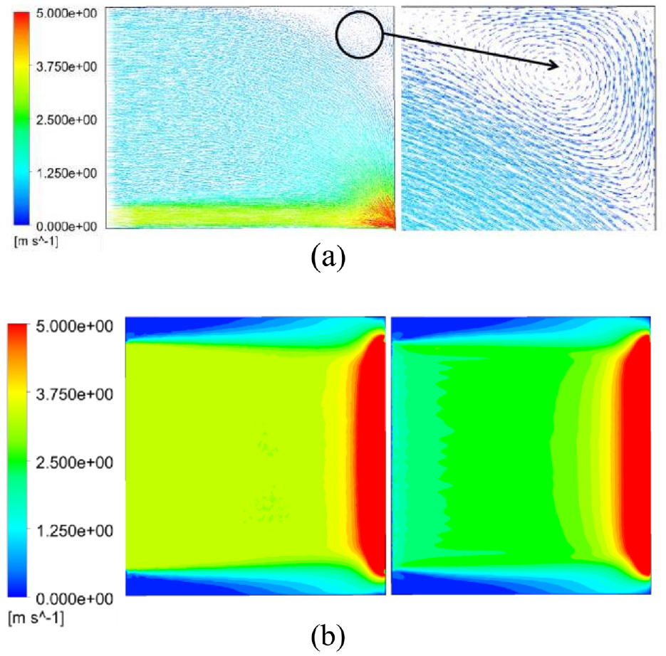
The obtained results of scheme 2 are presented in Figure 5. It is observed that the flow velocity of the bottom airflow in the inlet and middle sections has an upward trend, and increases from 2.0 to 3.3 m/s. The airflow velocity rises significantly at the outlet end, which is significantly different from the flow patterns in the inlet and middle sections. This phenomenon may be attributed to the larger air inlet area in scheme 2, which provides more flow. Therefore, when the gas flows to the outlet section, it converges and the flow velocity increases. Subsequently, a high-speed area forms in the middle of the nozzle airflow. Xiaokang 4 showed that this phenomenon significantly improves the splash removal rate. However, high-velocity gas flow adversely affects flow uniformity. More specifically, the deviation index of scheme 2 is 0.5338, which is more than that of scheme 1. The area where the airflow collides the wall is marked. It should be indicated that uneven gas flow in this area mainly originates from an increase in the airflow velocity and formation of the recirculation area.

Gas flow velocity in the chamber with a single normal inlet: (a) velocity vectors on the central YZ plane and (b) velocity contours on the clearing area and the machining face.
Effect of the large-size inlet on the flow uniformity
The simulation results of scheme 3 are shown in Figure 6. The airflow velocity distribution in the inlet section and the middle section is similar to that of scheme 1. The airflow velocity in the axial direction increases from 2 to 2.7 m/s, and that in the middle section remains uniform. At the outlet section, the flow rate increases due to the convergence of the gas flow. The deviation index of scheme 3 is 0.1538, and the flow uniformity is better than that of schemes 1 and 2. It can be seen from the above discussion that the design of the large-size air inlet can change the gas flow characteristics and improve the gas flow uniformity. It is worth noting that the powder entrainment and erosion phenomena need to be considered during the processing. Moreover, the maximum velocity of the bottom air flow in contact with the powder is limited by the threshold velocity of the powder, which also limits the maximum flow rate of the nozzle airflow. Consequently, the ability of scheme 2 to remove spatters is restricted, and the effect of removing spatter does not improve further.
Gas flow velocity in the chamber with a single normal inlet: (a) velocity vectors on the central YZ plane and (b) velocity contours on the clearing area and machining face.
Comparative analysis
Figure 7 illustrates the velocity uniformity index and the speed increase index of the three schemes. It is observed that the largest speed increase index occurs in scheme 2 with a segmented air inlet, which is beneficial to the removal of spatters. Moreover, the highest velocity uniformity can be achieved in scheme 3. In this scheme, the recirculation area is smaller than that of schemes 1 and 2. This is because the airflow enters from the inlet, collides with the inner wall, moves down along the inner wall, and converges to the outlet. Therefore, the recirculation area is squeezed by the airflow, the recirculation area reduces, fluctuations of the airflow velocity are small, and the velocity deviation index is 0.1538, indicating that the airflow has good uniformity. In schemes 1 and 2, a large reflux area forms above the chamber wherein the velocity deviation exponents are 0.3335 and 0.5338, respectively. These indices indicate that the airflow velocity fluctuates significantly. This phenomenon was previously explained for scheme 1. It is concluded that the movement direction of the gas flow after colliding the inner wall greatly affects the velocity uniformity and uneven velocity distribution mainly originates from the backflow.
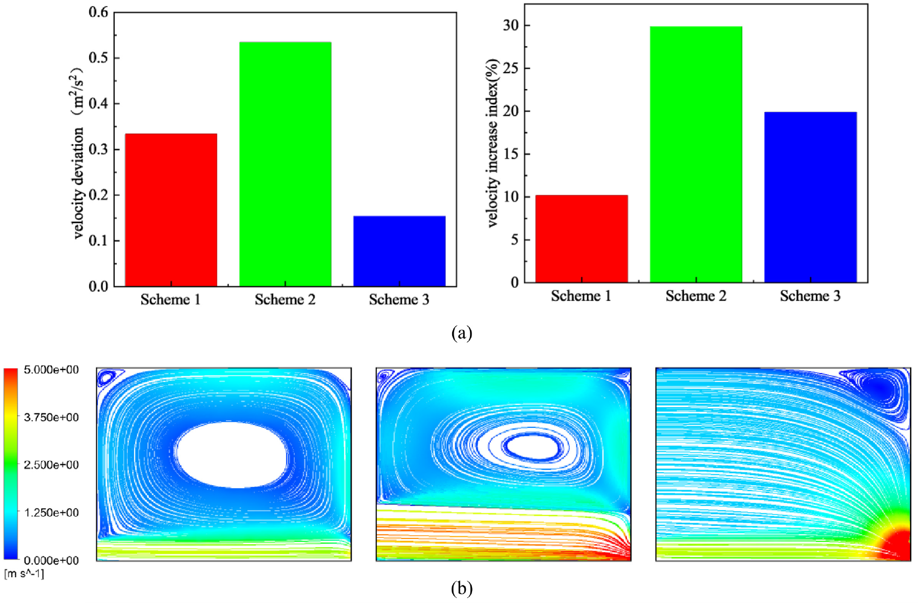
Comparative analysis of three schemes: (a) velocity deviation and velocity increase indices and (b) velocity contours.
Structural improvements
Figure 8 shows the configuration of the improved cavity structure. In this scheme, the advantages of schemes 2 and 3 are combined and a layered nozzle layout is adopted to redistribute the flow velocity. The airflow velocity of the bottom and upper layers of the nozzle is set to 3.4 m/s, while the airflow velocity of the middle layer is set to 4.6 m/s. In order to reduce the retention, a large-size inlet structure is adopted and the airflow speed is set to 1.0 m/s to limit the formation of backflow.
Layout of the air inlet in the optimized scheme.
The flow field of the improved scheme is analyzed. In this regard, Figure 9(a) shows that the overall flow velocity in the middle of the nozzle of the optimized scheme is improved. The retention area in the cavity is small and appears only in the upper right corner. The velocity deviation index is 0.102 m2/s2. The overall flow field maintains a good uniformity. Combined with the analysis in the previous section, it can be inferred that the increase in flow rate is due to the convergence of the airflow at the outlet section. The flow uniformity on machining surface can be optimized by changing the flow rate of large-size inlet.

Gas flow in the chamber with the optimization scheme: (a) velocity vectors on the central YZ plane, and (b) velocity contours on the clearing area and the machining face.
Figure 10 shows the velocity uniformity and airflow characteristics when adjusting the large-size inlet velocity. It is observed that there is a clear relationship between the large-size inlet velocity and the velocity uniformity in the chamber and on the machining face. More specifically, when the large-size inlet velocity exceeds 0.2 m/s, the manifold shape hardly changes, so the velocity uniformity does not change much. Moreover, as the gas velocity increases, the bottom surface velocity increases, which is because of higher flow convergence at the outlet end. When the flow velocity is less than 0.2 m/s, the manifold shape changes and the deviation index of the flow velocity increases significantly. Since the reduced flow velocity cannot squeeze the recirculation area, this area expands. Therefore, the highest bottom-surface airflow uniformity can be achieved when the large-size inlet velocity is set to 0.2 m/s. However, uniformity and velocity of the chamber airflow in the purge area are hardly affected.

Distribution of velocity-deviation and velocity-variation indices in middle section.
Conclusion
In the present study, a comprehensive three-dimensional numerical simulation of the atmosphere protection system of the SLM forming equipment is carried out. In this regard, three different inlet schemes are proposed, and the performance of each scheme is analyzed numerically. These schemes are (a) single inlet nozzle, (b) segmented nozzle, and (c) large area nozzle with a single inlet nozzle. The flow uniformity and velocity characteristics of different schemes are studied using the velocity deviation and speed increase indices. Among the studied cases, the highest flow velocity was achieved in the segmented air inlet, wherein the speed increase index was 29.83%. It is found that the inlet area significantly affects the flow uniformity in the chamber, and the velocity deviation index is 0.1538. Based on the performed analyses, the uniformity of the bottom surface velocity was improved significantly. The obtained results in this article are expected to provide a valuable reference for the design of SLM gas circuit systems.
Footnotes
Handling Editor: Chenhui Liang
Declaration of conflicting interests
The author(s) declared no potential conflicts of interest with respect to the research, authorship, and/or publication of this article.
Funding
The author(s) disclosed receipt of the following financial support for the research, authorship, and/or publication of this article: This work was supported in part by the Key-Area Research and Development Program of Guangdong Province, under Grant 2020B090924002, in part by Professional core curriculum construction “Mold Manufacturing Process” under Grant 202002049, in part by the Dongguan Sci-tech Commissoner, under Grant 20211800500102.
Data Availability
The data used to support the findings of this study are included within the article. Further data or information are available from the corresponding author upon request.