
Abstract
Pre-stressed steel wire-wound ultra-high-pressure vessels (PSWUPV) are commonly used in engineering to transport ultra-high-pressure media. However, the complex structure of these containers and the frequent pressure changes pose challenges in designing their structural and fatigue strength. Three simulation design methods were compared and analyzed: the two-dimensional force method, the two-dimensional cooling method, and the three-dimensional force method. The results showed that all three methods met the stress analysis requirements. The three-dimensional surface mass force method was chosen as the preferred method for engineering applications, specifically for the process of steel wire-winding loaded with mass force. The combined load case method was used to examine the influence of steel wires on the stress of the thick-walled cylinder when wound layer-by-layer. The study also focused on the changes in stress relaxation within the steel wire layer. The results demonstrated that the residual stresses of the core cylinder and the winding layer exhibited quasi-linear superposition during the winding and preloading process. The preloading effect of the steel wire weakened with increasing friction coefficient. Simulation results showed larger errors with excessively large or small normal stiffness coefficients. Based on theoretical solutions and verification studies, the optimal friction and normal stiffness coefficients were determined to be 0.02 and 1, respectively. By achieving a reasonable distribution of residual stress in the thick-walled cylinder of the ultra-high-pressure vessel through fatigue analysis, the fatigue life of the cylinder was significantly improved.
Keywords
Introduction
Winding the steel wires around the vessel via a pre-stressing force is one of the key technologies to achieve isostatic pressing technology, by which the vessel is wound and preloaded by steel wires with tension layer-by-layer on the outer wall of the thick-walled cylinder. The bearing capacity and strength of the cylinder can be significantly enhanced after the preloading, while its structural sizes and weight are remarkably reduced. Nowadays, there are three leading techniques for steel wire-winding. The theory of equal tension and uniform tangential stress winding was proposed by Comstock, 1 providing new ideas for the prestressed vessels. The theory of uniform shear stress steel wire winding was established by Gronbaek and Wanheim. 2 The permitted internal working pressure of the band-like uniform shear stress winding is 30% higher than that of the equal tension and uniform tangential stress winding. The theory of the constant maximum shear stress was developed by Maksimov. 3 From the engineering standpoint, it has been found that a “shear lip” with an angle of 45° to the spindle direction appears on the section of steel wire layer (SWL) during failure of the steel wire-wound cylinder. Therefore, compared with other winding theories, the theory of uniform shear stress winding can make more effective use of steel wire strength to improve itself and give full play to the material properties. As for the stress analysis and calculation of the pre-stressed pressure vessels, a new hypothesis was taken into account by Talako, 4 in which the cylindrical core cylinder and metal wire layer in order were modeled as thick- and thin-walled vessels. Additionally, the vessel was divided into two parts based on the presence of various materials. However, the calculation errors increase if the winding layer is supposed to be a whole. Fryer and Havery 5 assumed that the vessel of metal wire layer would be thin-wall and multi-layer according to the Lame relational expression. Compared with Talako’s hypothesis, the theoretical calculation accuracy was improved to a certain extent, and the parametric studies and discussion were better. The simulation calculation for the steel wire-wound vessel was also performed by Alegre et al. 6 via implementing the cooling method to evaluate the stresses within the core cylinder and SWL in each direction. The results showed that the distribution of the stress predicted by the cooling method would be also reasonable; however, the influence of the parameter setting on the stress values obtained by simulation calculation was not considered. The mechanics of fatigue crack was also investigated by Jahed et al. 7 and the thickness optimization analysis was performed for multi-layered cylinders. Nevertheless, the permitted number of cycles for the vessel was not estimated. The design requirements of the wound ultra-high-pressure vessels are specified in the Chapter KD-9, Section VIII of the American Society of Mechanical Engineers 8 (ASME) code, and these represent the theoretical comparison basis for simulation design. The research results of Guo et al. 9 indicate that simple circumferential winding provides high stiffness and strength, but is prone to local stress concentration. Oblique winding can reduce stress concentration and provide better isotropic performance.10–12 In applications that require both strength and toughness to be considered, complex three-dimensional winding can provide better performance. By analyzing the results of fatigue life tests, He 13 proposed a fatigue cumulative damage criterion for the steel wire wound forging hydraulic press based on Miner’s linear cumulative damage theory, which achieved safety assessment and life prediction of the steel wire wound forging hydraulic press.
Further, the previous research findings need to be improved in terms of simulation accuracy, influencing factors for all parameters, and fatigue life prediction. To this end, the processes of stretching and winding the steel wires unilaterally layer-by-layer by the uniform shear stress in the engineering are realized in this work. Additionally, the influences of the friction coefficient and contact stiffness between the winding SWLs on the pre-stressing force of core cylinder are also considered. The overall accuracy of the simulation method for the combined load case in the pre-stressed wound ultra-high-pressure vessel was justified by the theoretical calculation according to the ASME code. Fatigue analysis was also carried out on the pre-stressed wound vessel of internal pressure 200 MPa, and the maximum permitted number of cycles for the vessel was calculated to ensure its long-term safe and stable operation.
Theoretical calculation
The structural sketch of the PSWUPV is demonstrated in Figure 1. The inner and outer radii of the core cylinder are represented by ri and rif, respectively, and the outer radius of the winding layer is ro. The core cylinder is integrally forged, and the steel wires for winding are band-like flat steel wires. The winding initial stress is also presented in Figure 2. The continuous curve shows the relationship between the initial load of the winding layer and the radius during the preloading process. The whole winding layer is divided into 21 winding steps in the simulation calculation. The preloading initial load value of each step is simplified to the load value of the intermediate diameter for the current steps, just as the step-like broken line demonstrated in Figure 2. The minimum and maximum initial load forces in order are 476 and 703 MPa, respectively. The design life of the vessel is 15 years. It is estimated that the number of its working cycles per year is 300, and thus the total number of its working cycles is 4500.

The structural sketch.

The sketch map of the initial loading.
According to the special design requirements of the wire-wound vessel and frame in Chapter KD-9, Section VIII of the ASME code, the residual stress and deformation caused by the winding flat steel wires on the core cylinder are thoroughly calculated. During the winding process, the circumferential stress of the core cylinder, σt (x1), the radial stress, σr (x1), and the radial shrinkage, δ are evaluated using equation (1)14,15:

Besides, the residual circumferential stress of the winding steel wires, σt (x2) and the radial stress, σr (x2) can be displayed by the following relation14,15:

where Dw represents the instant outer diameter of the winding layer in mm, E is the elastic modulus of the material in MPa, and Sw (x) denotes the stress in the flat steel wire upon the completion of the winding operation in MPa.
The theoretical solutions of the stresses in each direction for the core cylinder of the steel wire-wound vessel and the steel wires during preloading are presented in Table 1.
Analytical solutions for the steel wire-wound vessel.

Through performing the theoretical calculations, it is understandable that there is a quasi-linear relationship between the radial and circumferential stresses of the core cylinder and the vessel radius. Under the preloading condition, the variation of the radial stress of the vessel across the thickness appears as a “V-shaped” trend, while the vessel circumferential stress presents a “mirror Z-shaped” trend. The rationality of the simulation calculation is also verified by the rules obtained through the theoretical calculations.
Simulation analysis
Materials
The cylindrical structure of the prestressed wrapped ultra-high pressure vessel is forged as a whole. The material used is ASME SA-723 Grade 3 Class 3, with its elastic modulus, Poisson’s ratio, density, and allowable stress listed in Table 2. The specification of the wrapping steel wire is 5 mm × 1.5 mm rectangular wire, with material grade UNS1566 and its material characteristics as shown in the table.
Physical parameters of barrel and winding layer materials.

In order to determine whether the container reaches the plastic stage under the condition of prestressing and operating conditions, and to ensure that the simulation analysis results can approximate the stress state in engineering practice, real stress-strain experiments were conducted on the thick-walled cylinder material SA-723. In the real stress-strain curve of the material, the elastic region is relatively short and there is no obvious yield plateau. When reaching the plastic stage, the material properties are significantly enhanced, as shown in Figure 3.

True stress-strain curve of SA-723 material.
Boundary conditions
Due to the axisymmetric nature of the model and the simulation calculation method for load combinations, the boundary conditions of the simplified finite element analysis are shown in Figure 4. In the 2D simulation analysis (a) and (b), points A and B represent symmetrical constraints, while point C represents the initial wrapping force of the winding step. The loading methods in (a) and (b) are mass forces and low temperature loads, respectively, with corresponding working pressure applied to the inner wall surface of the cylinder. For the 3D simulation analysis model (c) and (d), points A, B, and C are cross-sectional symmetrical constraints, and point D represents the initial wrapping force of the winding step. Additionally, frictional contacts are established between each layer of winding steps and between the first layer of winding step and the cylinder.

Simulation boundary conditions: (a) 2D line mass force method, (b) 2D cooling method, (c) 3D surface mass force method, and (d) 3D cooling method.
Within the structure of the ultra-high pressure vessel, there are inevitable contacts between the cylinder and each winding step, as well as between adjacent winding steps. Therefore, a total of 20 contact surfaces are established. All contacts are modeled as “soft” contacts, taking into account the deformation of each structure in the loading process, in order to accurately describe the influence of deformation on the pre-tightening effect. The contact elements used in the contact model created in this study are CONTA172 for the contact elements and TARGE169 for the target elements.
Discussion on the simulation research methods
Three approaches are taken into account for the exertion of loads, including the two-dimensional cooling method, two-dimensional line mass force method, and three-dimensional surface mass force method. All these methodologies were employed in simulation analysis and calculation. For the two-dimensional cooling method, the expansion properties of metal materials with heat and contracting with cold were exploited, and the low-temperature load was applied to the two-dimensional model of the steel strip layer. During this process, the displacements at both ends were appropriately restrained in the simulation calculation such that the shrinkage stress reached the initial load value. Regarding the two-dimensional linear mass force method, a displacement constraint was only imposed at one end of the two-dimensional model steel strip layer, and a linear mass force was exerted at the other end. For the three-dimensional surface mass force method, a surface displacement constraint enforced at one end of the three-dimensional model steel strip layer, and a surface mass force exerted at the other end. The schematic diagrams of the boundary conditions of the three simulation methods are presented in Figure 5. Figure 5(a) and (b) shows a two-dimensional analysis method, so the load is applied on the boundary line. Figure 5(c) shows a three-dimensional analysis method, where boundary conditions are applied to the boundary surface.

The considered boundary conditions for the three simulation methods: (a) two-dimensional cooling method, (b) two-dimensional line mass force method, and (c) three-dimensional surface mass force method.
The calculation results of both radial and circumferential stresses of the three simulation methods are demonstrated in Figure 6. The peak values and variation laws of these stress fields are basically consistent in the plane model, whether with the line mass force method or the cooling one. However, in the three-dimensional model calculation, the peak value of the radial stress calculated by the loading surface mass force method is relatively conservative, and the pre-stressing force in the core cylinder does not apparently vary with the thickness of the core cylinder. Although more accurate solutions could be obtained by utilizing a few cells in the two-dimensional model when the distribution of the radial and circumferential stresses far away from the discontinuous region, the finite boundary model or the research method may not be applicable, particularly in the presence of axial stress. Moreover, only the three-dimensional model can be exploited for fatigue analysis, while the three-dimensional surface mass force method has specific advantages in simplifying the boundary conditions and interpreting the stress and fatigue analysis results.

Comparative analysis of the stress values generated by different simulation calculation methods: (a) radial stress and (b) circumferential stress.
On the basis of the discussion given on the above-mentioned simulation research methods, the three-dimensional surface mass force method is chosen for further analysis. More specifically, this approach has been employed to examine the influences of the uniform shear stress steel strips on the pre-stressing force of thick-walled vessel cylinders during the winding process and the stress relaxation of the steel strips. In the present study, a novel methodology was used to simulate the winding process of the steel wires, where the winding steel wires were assumed to be several thin-walled cylinders. Further, the winding preload was imposed on each thin-walled cylinder sequentially from inside to outside in the simulation calculation such that the winding process of the steel wires could be simulated layer-by-layer. Then, all the obtained results were superimposed and combined to attain the stress solution of both core cylinder and winding layer subjected to the preload. To this end, the preloading effects of each layer of thin-walled cylinders on the core cylinder structure were separately evaluated with particular care. The radial and circumferential preloads produced by the first steel wire-winding layer are −9.29 and −55.6 MPa (Figure 7), while those generated from the second steel wire-winding layer in order are −8.2 and −49.15 MPa, respectively (Figure 8). According to the plotted results in Figures 7 and 8, the distribution of the radial stress of the vessel as a function of the vessel thickness still presents a V-shaped trend, while that of the circumferential stress shows a mirror Z-shaped trend.
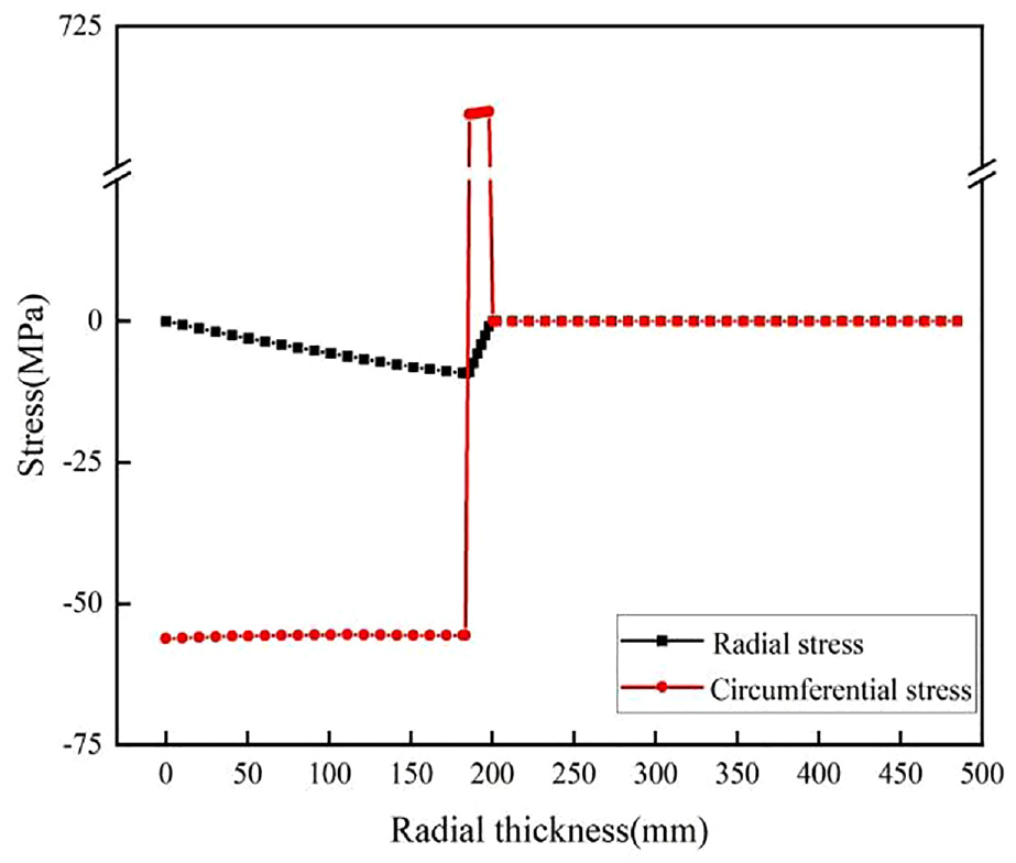
Preloading effects of the first winding layer.

Preloading effects of the second winding layer.
The preloading effect of each layer of steel wire winding layer is shown in Table 3. When the 21 SWL steps are wound, the preloading effects of the whole winding layer on the interface of the core cylinder and the winding layer are extracted by calculating the combined load case. As a result, the radial and circumferential stress values are predicted to be 94.19 and 572.63 MPa, respectively.
Preload at the interface provided by each winding step layer.

As shown in Figure 9 and Table 4, the residual circumferential stress of the first step is determined to be 703 MPa when only one step is wound. After operating the winding program, the residual circumferential stress of the first step gradually relaxes. When all the steps are wound, the residual circumferential stress of the first and 21st steps in order are 226 and 476 MPa, respectively.

Residual stress relaxation results of each step.
Circumferential stress relaxation during the winding process (unit: MPa).

Comparison of the theoretical and simulation solutions
The analytical and simulation solutions based on the ASME philosophy are comparatively analyzed, and it is observed that the stress distribution of both radial and circumferential stresses is basically consistent (Figure 10). At the interface of the core cylinder and the winding layer, the radial and circumferential preloads in order are predicted to be 94.19 and 572.63 MPa, respectively. In accordance with the ASME philosophy, the radial and circumferential preloads are calculated to be 100.09 and 574.6 MPa, with relative errors of 5.89% and 0.34%, respectively. The small error not only verifies the feasibility of the winding process simulation but also reveals the rational selection of friction coefficient and normal stiffness coefficient in the simulation process. The influence law of the two parameters on the simulation results is discussed as follows.
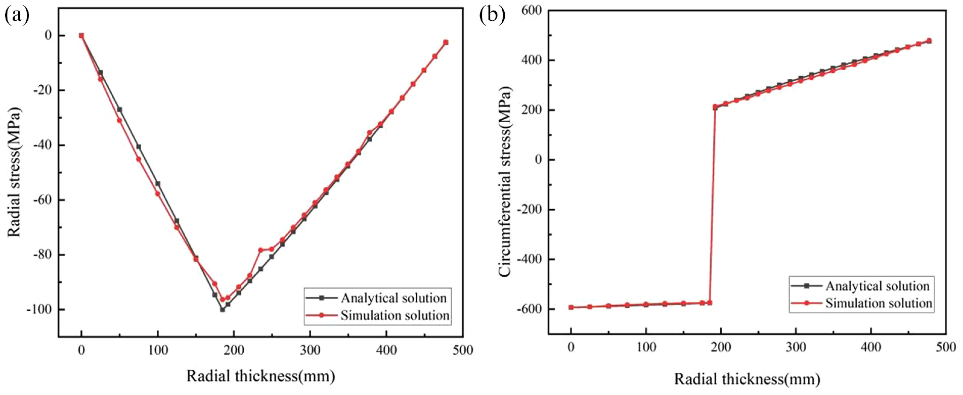
The predicted stress values based on the analytical and simulation approaches: (a) radial stress and (b) circumferential stress.
Optimal friction coefficient
The cylinders are influenced by the strengthening effects in both circumferential and axial directions due to the friction of the ribbon wires and the static friction force between the metal layers in the pre-stressed winding vessels. For this reason, the effects of the friction coefficient between the metal layers on the vessels should be taken into account in the finite-element simulation process. The friction contact exists in each thin-walled cylinder, and the acting force between layers is transmitted through friction elements during the simulation process of the uniform shear stress winding. In the present scrutiny, such effects for the friction coefficients of 0, 0.02, 0.2, 0.4, 0.6, and 0.8 on the core cylinder structure are considered. The distributions of the radial and circumferential stress values for various friction coefficients are demonstrated in Figure 11.

The preloading effects for different friction coefficients: (a) radial stress and (b) circumferential stress.
The results reveal that with the increase in friction coefficient, the preloading effects of the simulation calculation are weakened gradually. When the friction coefficient is set equal to 0.2, the radial preload is determined to be 87.89 MPa with a relative error of 12.19%. For the case of friction coefficient equal to 0.8, the radial preload is predicted to be 56.09 MPa with a relative error of 43.96%. A more detailed survey of the obtained results indicates that for the cases of the friction coefficients equal to 0.02, 0.2, and 0.8, the relative errors of the circumferential stress for the outermost winding layer are 1.3%, 14.3%, and 46.21%, respectively. Further, the zero friction is not consistent with the actual situation; therefore, the calculated stress value may be closer to the real solution when the friction coefficient is equal to 0.02.
Optimal normal stiffness
For the vessels wound by steel wires, each thin-walled cylinder is preloaded by tightening. During the simulation process, the normal stiffness of contact pairs is also one of the factors affecting the accuracy of the simulation results. The influence of the normal stiffness on the generated stress fields within the core cylinder structure is examined for the normal stiffness coefficients of 0.01, 0.05, 0.1, 0.5, 1, and 5. The plots of both radial and circumferential stress values for various normal stiffness coefficients are displayed in Figure 12.
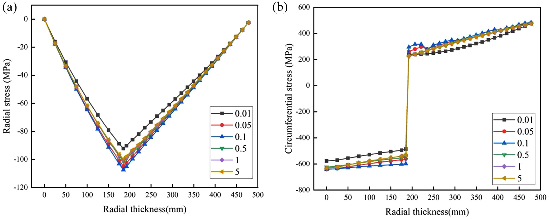
The preloading effect for various coefficients of the normal stiffness: (a) radial stress and (b) circumferential stress.
Based on the analysis results, the relative discrepancies between the predicted radial stresses of the core cylinder and those of the theoretical calculation for the normal stiffness coefficients 0.01, 0.5, 1, and 5 are 7.9%, 1.35%, 0.33%, and 1.44%, respectively. Consequently, the calculation results are closer to the real solution when the normal stiffness coefficient is set equal to 1.
Fatigue evaluation
Fatigue is one of the main reasons for the failure of engineering components. The fatigue failure is the process where a certain point or some points bear the cyclic stress in the structure, and cracks or even complete fracture failure is formed after the action of sufficient cyclic disturbance. The pressure vessel wound by steel wires is a typical alternating load, which repeats the process of pressurization and pressure relief in operation. 16 Although the core cylinder structure is always subjected to compressive stress load under the action of preloading, it can cause fatigue failure of the core cylinder in a long-time operating cycle. 17 As for the fatigue failure, the stress amplitude is more significant than the maximum stress allowed for the structural members. The larger the stress amplitude the shorter the fatigue life. The fatigue failure does not occur when the stress amplitude is less than a fatigue limit. Furthermore, whether the member has infinite life, in theory, could be determined by comparing S-N curves.
The vessel stress under 200 MPa internal pressure is calculated, and the principal stresses are extracted along the radius direction by employing the above-mentioned simulation method. As shown in Figure 13, three points on the outer wall, middle section, and inner wall of the core cylinder are chosen along the radius direction to calculate the fatigue life of the core cylinder. The mean value of the alternating stress amplitude and the principal stress sum are obtained by evaluating the principal stress difference and sum at the indicated points (Figure 14). Subsequently, the equivalent alternating stress intensity amplitude is derived after calculating the average stress. The cycle number of the core cylinder is calculated by comparing and examining the S-N curve’s results presented in Table 5.

Schematic diagram of the considered points.

Fatigue analysis steps.
The evaluated allowable cycle number.

The allowable cycle number N (N = 100,000 > 4500) in normal operation is commonly higher than the expected design life of 15 years.
Conclusions
The two-dimensional cooling method, two-dimensional linear mass force method, and three-dimensional surface mass force method were employed in conjunction with the ASME philosophy and finite-element method to simulate and analyze PSWUPVs. The three calculation methods met the requirements of stress analysis. In consideration of this engineering problem, the three-dimensional loading surface mass force method was preferentially selected, and the influencing factors such as the friction coefficient and normal stiffness between the winding layers were fully discussed for fatigue analysis. The main obtained results are as follows:
The three-dimensional loading surface mass force method is relatively consistent with the engineering loading pattern. Additionally, the calculation method of the combined load case restores the winding process in the engineering practice, and the stress relaxation effects of the back-winding layer on the inner winding layer are fully taken into account. As a result, the simulation solution is more consistent with the theoretical solution.
The friction coefficient and normal stiffness are two main factors affecting the simulation accuracy. The optimal friction coefficient of the contact pairs between the winding layers is 0.02, while the optimal normal stiffness coefficient is equal to 1.
The fatigue analysis reveals that the pre-stressed wound ultra-high-pressure vessels may have better fatigue resistance.
Footnotes
Handling Editor: Chenhui Liang
Declaration of conflicting interests
The author(s) declared no potential conflicts of interest with respect to the research, authorship, and/or publication of this article.
Funding
The author(s) disclosed receipt of the following financial support for the research, authorship, and/or publication of this article: This work was supported by the Beijing Nova Program (Grant no. 2022139), and the authors are grateful to China Iron & Steel Research Institute Group for supplying the required simulation software.