
Abstract
As the main friction pair of engine, the friction loss of piston-cylinder liner assembly in the working process has become the main reason of engine friction power consumption. Many species in the biological world have formed non-smooth forms of resistance reduction after thousands of years of survival and evolution. Many people have applied this non-smooth shape of drag reduction on organisms to the surface of friction pairs in construction machinery. Based on LX108 engine, the wear and erosion resistance of Scapharca subcrenata surface is applied to the piston skirt, which is the main friction pair in the engine. Nine test schemes were designed according to orthogonal test. This design selects three factors, namely, groove distribution type, groove depth and width, groove spacing, and each factor includes three levels. The macroscopic fluid lubrication state of the whole piston skirt with bionic shape is studied. Through the change of oil film thickness caused by thermal-mechanical coupling deformation of skirt, combined with the average Reynolds equation, the hydrodynamic pressure of lubricating oil, shear stress, and skirt friction force are obtained to verify the contribution of bionic shape to piston drag reduction, wear reduction, wetting increase, and friction power consumption. The simulation and test results show that the lubrication of all parts of the bionic groove piston skirt is better than that of the standard piston; When the depth and width of groove is 0.8 mm and the spacing is 10°, the thicker the oil film thickness of skirt is; The bionic piston whose oil film bearing area is 74%–87% of the standard piston has the smallest normal pressure and friction; When the upper end of the skirt is arranged with groove shape and the lower end is arranged with narrow groove shape between wide grooves, the lubrication effect is better.
Introduction
As the most important and common means of transportation in people’s daily life, automobile has become the biggest consumption source of internal combustion engine market. 15% of the total combustion energy of internal combustion engine is lost in mechanical motion, and a large part of the loss is caused by friction. Reducing the friction loss of engine can save oil by 2%–5%, and the friction power consumption produced by the friction pair of piston-cylinder liner system is as high as about 50% of the friction loss of the whole internal combustion engine.1–3 The research on the friction and wear performance of piston-cylinder liner system, which is known as the “heart” of internal combustion engine, has been paid much attention. In order to improve its wear resistance, people have done a lot of extensive research work on piston-cylinder system from many aspects such as material, structure, and processing technology. Due to space limitation, this paper only introduces the development status of the piston structure related to this design.
Improvement of piston structure of internal combustion engine
Zhao Jianrui designed two kinds of cooling oil passage pistons: open and closed. Closed cooling oil passage piston is completely closed. The piston with open cooling oil passage is closed above the piston ring groove and pin hole, and the skirt is open. In order to spray the cooling oil into the closed oil passage smoothly and play a role of oscillating flow, the nozzle is arranged at the opening of the oil passage. The piston can reduce the working temperature of piston and cylinder liner, and reduce the probability of adhesive wear and thermal fatigue failure of piston. At present, this design is mostly used for pistons with a cylinder diameter of about 150 mm. 4 Variable compression ratio (VCR) internal combustion engine has great potential to improve fuel economy, and has become a hot spot for internal combustion engine improvement, but it is very difficult to popularize it into commercial application. 5 Dong Jian, a Chinese scholar, proposed to improve the piston of the variable combustion chamber internal combustion engine. This design not only replaces the complex hydraulic-electronic control device, but also ensures that the piston can quickly respond to the changes of the internal combustion engine under various working conditions. In this study, a VCC (variable combustion chamber) mechanism is designed on the piston and a reset cam is installed at the small end of the connecting rod. VCC mechanism is composed of disc spring, steel ball, support plate, and limit plate. The supporting disc is rigidly connected with the piston skirt, and the limiting disc is rigidly connected with the top of the piston. Steel balls are uniformly distributed in the V-shaped groove formed between the limit plate and the support plate, and a disc spring is arranged between the steel balls and the piston top. When VCC piston works, it first enters the pre-tightening state; After that, when the pressure in the cylinder is greater than the set pre-tightening force, the piston top and piston skirt form relative displacement. At the last exhaust stroke, the pressure in the cylinder decreases rapidly, and the disc spring resets the skirt. The fuel economy of a non-supercharged gasoline engine (original compression ratio 9.5) converted into a VCC internal combustion engine (compression ratio 12.0) is verified by simulation. The fuel economy is improved by about 20% under low load conditions and about 10% under high load conditions.6,7 Michal Pyrc et al. done the presented work, which concerns experimental research of a spark-ignition engine with variable compression ratio (VCR), adapted to dual-fuel operation, in which co-combustion of ammonia with hydrogen was conducted, and the energy share of hydrogen varied from 0% to 70%. For 12% of the energy share of hydrogen co-combusted with ammonia, the most favorable course of the combustion process was obtained, the highest engine efficiency and the highest IMEP value were recorded. The conducted research shows that increasing the H2 share causes an increase in NO emissions, for both analyzed compression ratios. 8
By changing the local shape of the piston to extend the life of the piston, many scholars and manufacturers have their own ideas. Ferrocomp forged steel head and forged steel skirt combined piston developed by Mahler Company of Germany. Forged steel head is 42CrMo4, forged steel skirt is 38MnVS6, and head and skirt are connected by bolts, which greatly improves the rigidity and bearing capacity of piston in large cylinder diameter internal combustion engine. After that, Mahler Company developed Monotherm piston, which is made of monolithic forged steel. Although its quality increases, its service life is longer. It has been mass-produced and applied to Euro III and Euro IV heavy trucks. 9 S. Kaliappan et al. developed the trapezoidal piston profiles for an IC engine (Internal combustion engine). This study is aimed at a comparative investigation on two different velocity profiles for piston movement namely Sinusoidal and Trapezoidal Profiles for an IC Engine. A proposed connecting rod configuration with internal gear and pinion arrangement is proposed to achieve different Trapezoidal Profiles. The optimum CFD (Computational Fluid Dynamics) procedure found from validation study is used to analyze and understand the engine with modified Trapezoidal Velocity Profiles. There is almost 20% reduction of mean piston velocity that considerably improves hydro-thermo dynamic and mechanical characteristics of the existing engine. 10 Anh Tuan Le’s study, three different designs of piston bowl geometry in a retrofitted compressed natural gas engine were investigated in relation to engine performance and its combustion characteristics. As a result, the application of concentric bowl-in-piston and compression ratio of 11.5:1 was found to yield the lowest brake specific fuel consumption and the highest brake power. 11 Limin Wu study on the effect of piston skirt profile on the vibration behavior of non-road high pressure common rail diesel engine. The effects of piston skirt profile on the dynamic behavior of piston and the vibration characteristics of engine block is studied synthetically by the method of a combination of experimental test and numerical simulation. The results show that the mechanical vibration of engine block will become more severe with the hiking up of bump position at the piston skirt. Vibration noise performance can be significantly improved by adjusting the bump position of piston skirt downward. 12 The research of Yin Bifeng et al., that showed that appropriately increasing the depth of the cavity can improve the wear within a certain range. However, if the cavity depth increase too much, the abrasion of the main thrust surface will be aggravated. After optimizing of the clearance and adopting the double-bump profile on the main thrust side, the accumulated wear load of the piston can be significantly reduced and its friction and wear performance will be improved. 13 Sergey G. Belchev et al., put forward that pistons with altered form of the piston skirt contact area are presented in this paper. The use of such pistons does not change the degree of liquid friction. There is a significant change in the forces of dry friction at rest which is the reason for the friction power reduction and the mechanical losses of the pistons with a special form of the contact surface. 14
There are also designs that reduce friction and wear by improving piston surface lubrication, and prolong piston fatigue life and overhaul times. For example, “Piston for Prolonging Engine Service Life” invented by Han, 15 several tapered blind holes and several tapered through holes are arranged in piston skirt to realize continuous forced lubrication function. The “Piston for Internal Combustion Engine” invented by Nissan Automatic Car Co., Ltd. 16 has an extended striped groove with a groove spacing of 15–30 μm and a depth of 5–15 μm on the outer surface of the piston skirt, which has the function of providing lubricating oil carrying. Azevedu et al. 17 invented the “piston skirt articulated piston,” and the surface of the combined piston skirt is also grooved. Jongdae Kang et al., studied to determine whether piston friction can be reduced by applying a micro-pattern to the skirt portion of the piston, which accounts for the largest proportion of engine parts. A hexagonal shape that is representative of bionic textures was selected for the micro-pattern, and circular and cross-hatch patterns were additionally produced for comparison. The friction experiments with the patterning pistons confirmed that friction was reduced by up to 6.74% by adjusting the spacing of the hexagonal pattern. It was also confirmed that friction was reduced in the cross-hatch pattern by up to 5.28%. The friction reduction effect may vary depending on the parameters used for a specific pattern. 18 The study of Ali Usman et al. combines surface texturing with the coating approach to investigate the frictional response. Results show a remarkable reduction in friction and encourage the pattern-based development of surface coatings to extend the benefit across lubricating regimes. Consequently, the surface coated with optimized patterns had 7.98 ± 0.34% reduced energy loss per engine cycle as compared with the surface coated without a pattern. 19 Asoyan A.R. et al. considers the possibility of reducing the wear of piston skirts by reducing the contact surface in conjugation and providing an oil film in the friction zone, regardless of engine operating conditions. This opportunity is realized by forming a certain macro profile on the working surface of the piston skirt. The formation of the macrorelief was carried out by means of surface plastic deformation, with the reciprocating movement of a spherical tool on the machined surface. 20
The research on drag reduction and wear resistance of bionic non-smooth surface has been going on for many years, and some achievements have been made, many of which have been put into use and achieved good results. The key laboratory of engineering bionics of the Ministry of Education of Jilin University is particularly prominent in this field. Through experiments by Academician Ren Luquan and Dr. Deng Baoqing, it is found that the wear resistance of specimens with non-smooth surfaces is better than that of specimens with smooth surfaces, whether in mixed lubrication or quasi-lubrication.21,22 Academician Ren Luquan invented the “non-smooth piston on skirt surface.” 23 The oil hole of oilcloth is rectangular or parabolic, and the through hole is processed at a certain angle in the skirt, which is between 8° and 30°. This through hole with angle can realize natural oilcloth oil collection.
Lightweight improvement of internal combustion engine piston
During the reciprocating motion of the piston, there are extremely increasing and decreasing accelerations in both axial and radial directions, resulting in inertial force far greater than the gravity of the piston itself. In order to ensure the stable operation of the internal combustion engine, it is necessary to increase the fuselage mass as a balancing load. 24 Gravity itself does no work in horizontal motion, but it increases frictional resistance. Therefore, reducing piston mass can greatly reduce the mechanical loss of internal combustion engine. 25
For high-speed diesel engine, the volume and mass of piston can be reduced by reducing the relative height of piston, that is, the ratio of piston height H to piston diameter D. For example, Nissan RD series pistons have a diameter of 135 mm and a height of 137 mm, and an H/D ratio of about 1.0. 26 Reducing the piston compression height can also reduce the piston mass, and the material mass in the piston compression height range is about 80% of the total piston mass. 27 Asymmetric design of primary and secondary reasoning surfaces of piston can also reduce the mass of piston. The Evotec piston designed by German Mahler Company has an asymmetric window wall, and the inner side window wall of the main push which is under great stress is narrow, which ensures the stiffness of each part of the skirt and reduces the piston mass. The wall thickness of Advanced Elastoval II piston developed by American Huimen Company is only 2.5 mm, which is 62.5% of the wall thickness of ordinary piston, and its mass is reduced by nearly 20%. 28 Ford Company developed a lightweight piston with aluminum alloy head and plastic skirt, which reduced the piston mass by 30%, increased the linear speed by 10% and reduced the average effective pressure by 18%. 29 Mazda has developed a CRM (Reinforced Metal Foam) alloy piston and applied it to the SL 3.5 L DI internal combustion engine on a medium Titan truck. That is to say, a new nickel foam aluminum alloy composite material is cast around the cooling oil cavity on the piston. The piston mass is reduced by 10%, the service life is increased by two times, the power is increased by 10%, and the wear amount is reduced by 20%. 30
Piston is the main moving part of internal combustion engine, and its working environment is the worst. The reciprocating motion of piston in cylinder is not only impacted by various mechanical loads, but also subjected to high periodic thermal load. The contact friction between piston skirt and cylinder, poor heat dissipation and high temperature corrosion all make piston prone to fatigue failure. 31 If the friction and wear of piston skirt can be improved, it will play an irreplaceable role in reducing mechanical loss of internal combustion engine, reducing fuel consumption and improving environment.
Bionics is a comprehensive science that studies the structure, characteristics, functions, energy conversion, information control, and other excellent characteristics of biological systems, and applies them to technical systems, improves existing technical engineering equipment, and creates new technical systems such as technological processes, building configurations, and automation devices. 32 After hundreds of millions of years of evolution, the creatures on the earth have formed perfect body surface structure, body function, ability to adapt to the environment and maintain ecological balance. 33 After long-term adaptation, transformation and destruction of the earth’s environment, human beings have now realized the necessity of mutually beneficial coexistence with nature. Energy saving and emission reduction, reducing the pressure of human survival and creating economic benefits, people have learned all special skills from biological imitation.34,35
Scholars of various countries focus on the following three aspects of structural improvement of internal combustion engine pistons: Variable compression ratio piston by adding a mechanism, the piston can quickly respond to the changes of internal combustion engine under various working conditions. By changing the local shape of the piston to extend the life of the piston, such as changing the shape of the piston skirt, the top of the piston bowl, etc. There are also designs that reduce friction and wear by improving piston surface lubrication, and prolong piston fatigue life and overhaul times. At the same time, reducing piston mass and inertia force can improve piston fuel economy. For lubricating oil, a viscous liquid, shear stress will be produced on its moving surface, which is the root of friction between piston and cylinder. In this paper, LX108 aluminum alloy engine piston is used as the test workplace. In order to improve the lubrication effect and service life of the piston, the wear and erosion resistance of the shell surface is applied to the piston skirt, which is the main friction pair in the engine. The shell surface shape was applied to the piston skirt for the first time to improve the bionic shape design, and the optimal bionic shape in drag reduction and wear resistance was optimized through the orthogonal test design. In this work, the macroscopic fluid lubrication state of the whole piston skirt with bionic shape will be studied. Through the change of oil film thickness caused by thermal-mechanical coupling deformation of skirt, combined with the average Reynolds equation, the hydrodynamic pressure of lubricating oil, shear stress, and skirt friction force are obtained to verify the contribution of bionic shape to piston drag reduction, wear reduction, wetting increase, and friction power consumption.
Standard piston finite element analysis
The parameters of the tested engine are shown in Table 1.
Test engine parameters table.

Piston dynamics analysis
The force analysis is carried out on the piston 36 (as shown in Figure 1), it is matting for the finite element analysis of piston later. All forces of piston transform relevance to the crankshaft angle.
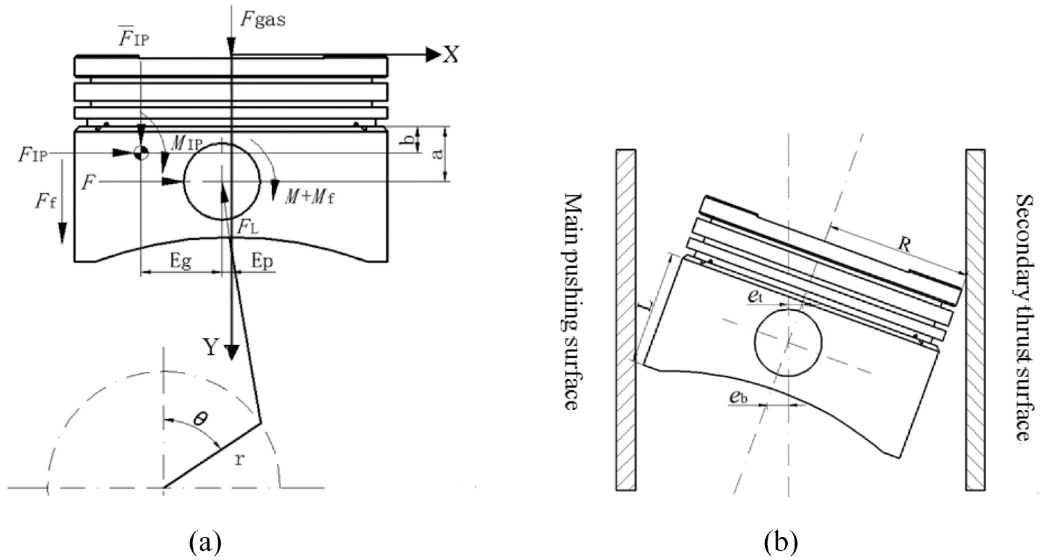
Piston force and structure size: (a) force analysis of piston and (b) structural dimension.
The equation for displacement, velocity, and acceleration of piston in the cylinder, as follow:


where, r is crankshaft radius; ω is crankshaft revolving speed; θ is crankshaft angle; C = Ep + rsinθ, Ep is piston pin eccentric; l is connecting rod length.
The piston reciprocating inertia force:
Lateral acceleration by the top of the second order piston

Where, L is skirt length, mm;
Piston axial center line and connecting rod of angle:
Force and moment acting on the piston of equilibrium equation is as follow.
The force balance equation of the piston in the x direction is:

The force balance equation of the piston in the y direction is:

Piston torque balance equation is:

where, Fgas is gas pressure at the top of the cylinder; Ff and Mf are friction force and friction moment; FL is connecting rod of reaction force; F, M are normal force and its moment; a is distance between the top of piston skirt and pin center; b is axial direction distance between the top of piston skirt and piston centroid; Eg is radial direction distance between piston centroid and pin center.
Thermal analysis of piston
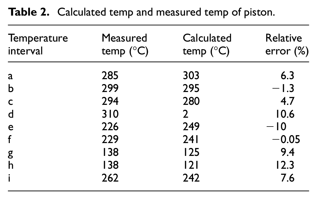
The work of engine is instantaneous condition. Temperature distribution of piston is steady state, after it enters normal operation condition. Base on boundary temperature and heat transfer coefficient of experiment piston, it calculates temperature of every temperature interval (as shown in Figure 2). It is comparative calculated value and measured value as shown in Table 2, and calculated value is all in the range of allowable error. 37 The detailed calculation process and actual test values of the calculated data in Table 2 are derived from Wu et al. 37

Temperature range.
Calculated temp and measured temp of piston.
The thermal-mechanical coupling FEM of piston
It could be established start of suction stroke when crank angle at 0°, main thrust face of piston and air cylinder is the closest when crank angle at 390°. 38 So it firmly believes that piston skirt is in the worst condition when bent axle in the maximum speed and at this crank angle. It left them as boundary conditions, and does thermal-mechanical coupling FEM (Finite Element Method) on piston-cylinder liner system. Pressure at the top of piston, inertia force, piston skirt lateral pressure are calculated at the worst condition. Based on ANSYS finite element analysis software, the piston-cylinder liner of material performance parameter units are unified. Mapping and smart mesh are used for meshing standard piston-cylinder liner (as shown in Figure 3). Tetrahedron is selected for meshing of all parts of piston cylinder liner system, and contact unit is selected for contact surface. The global meshing accuracy is 2. The whole piston is divided into smart grid default dimensions. Cylinder liner and pin are mapped and meshed, and other components are smart meshed. The number of nodes on the piston is 250,650 and the number of units is 144,714.
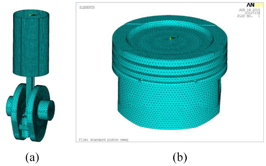
Divide polygon mesh units: (a) meshing of standard piston-cylinder liner and (b) meshing of standard piston.
It does thermal-mechanical coupling with indirect coupling method on standard piston. 39 First, it loads thermal loading on the piston and gets the analysis result; second, it puts gas pressure, inertial acceleration, and thermal analysis result on the piston and sets the constraint on piston-cylinder liner; finally, it gets the results of thermal-mechanical coupling analysis (as shown in Figure 4).

Limited element analysis results of standard piston: (a) stress and (b) deformation (magnification 50 times).
The piston finite element analysis results can be seen that stress reduce gradually from bottom to top of skirt, and reduce gradually from piston top to the third ring groove, and largen in oil return hole. Stress of radial piston distributes balance. Finite element analysis of method of bionic pistons are the same as standard piston.
Research on design of bionic piston
Determination of bionic groove size
Shell is composed of strong natural mineralized materials, and its surface is arranged with striped ridge structure with anti-wear and anti-erosion, which makes it survive in turbulence mixed with various hard objects and sediment containing corrosive substances for a long time and throw it intact. Shell overturning in silt is similar to piston moving in cylinder, both of which are solid-solid contact and lubricating liquid exists on the contact surface. In this paper, scapharca subcrenata is selected as a bionic prototype, and its shell surface structure is applied to the piston skirt of engine. The adult shell of scapharca subcrenata is 4–5 cm long, and the shape is thick and wide, and striped ridges are arranged on the shell surface. The width of ridges ranges from 1.1 to 1.6 mm, the spacing between ridges ranges from 0.5 to 0.8 mm 40 (as shown in Figure 5). In this paper, according to the external dimensions of the experimental piston, based on the structural dimensions of the ridge on the surface of the clam, the grooves are machined in the piston skirt along the axial direction of the piston, and the range of bionic groove spacing is 8–12 mm, the range of groove depth is 0.8–1 mm, and the range of groove width is 0.8–1 mm.

Non-smooth surface of scapharca subcrenata: (a) scapharca and (b) surface of scapharca shell.
Orthogonal test scheme for bionic groove piston
After being eroded by turbulence, scapharca subcrenata finally rotates to a state where the ridge is consistent with the turbulence direction because of its unique shape. Sediment collides and erodes the shell along the ridge surface. Therefore, in the design of this paper, grooves are designed along the axial direction on the piston skirt surface running at high speed (see Figure 6 for details). In the process of periodic collision between the skirt surface with grooves and the inner wall of the cylinder, the skirt wear is reduced, the thermal stress is unloaded, and fatigue failure is not suitable during working.

Bionic groove in the piston skirt.
The grooves are evenly distributed in the piston skirt in the form of vertical rows, and the grooves run through the whole skirt, that is, the length of the grooves is equal to the skirt length, the row direction is along the circumferential direction of the piston, and the row direction is along the axial direction of the piston. (See Figure 6 for details)
This design selects three factors, namely, groove distribution type, groove depth and width, groove spacing, and each factor includes three levels.
Factor 1: groove distribution type includes three levels, which are groove shapes as shown in Figure 7(a), through-holes between grooves as shown in Figure 7(b), narrow groove between wide grooves as shown in Figure 7(c). Through-holes between grooves is to clamp through holes between each two vertical grooves, the distance between the center line of the first row of holes and the top of the piston is 24 mm, and the holes are evenly distributed in six rows with a row spacing of 5 mm. Narrow groove between wide grooves, a shallow narrow groove is designed sandwiched between every two vertical grooves.
Factor 2: the groove depth and width include three levels, they are the groove depth is set to 0.8, 0.9, and 1 mm, and the groove width is equal to the groove depth. The corresponding dimensions of groove width and hole diameter are: groove width (hole diameter) 0.8 (0.5) mm, 0.9 (0.6) mm, and 1 (0.7) mm. Narrow groove is sandwiched between wide grooves. The corresponding dimensions of wide groove and middle shallow narrow groove are wide groove width (narrow groove width) 0.8 (0.5) mm, 0.9 (0.6) mm, and 1 (0.7) mm, and the depth of narrow groove is equal to the width of narrow groove. (See Figure 8 for details)
Factor 3: groove spacing includes three levels. Seen from the top of the piston, the groove spacing is centered on the radial central axis of the piston, and the groove row spacing is 8° (11 grooves), 10° (9 grooves), and 12° (7 grooves). (See Figure 15 for details)
According to the above bionic piston design principle, the orthogonal table L9 (33) is selected to compile the simulation experiment scheme, 41 as shown in Table 3.

Three types of grooves distribution: (a) groove shapes, (b) through-holes between grooves, and (c) narrow groove between wide grooves.

Groove size.
Simulation test of bionic groove piston.

Lubrication model of piston skirt
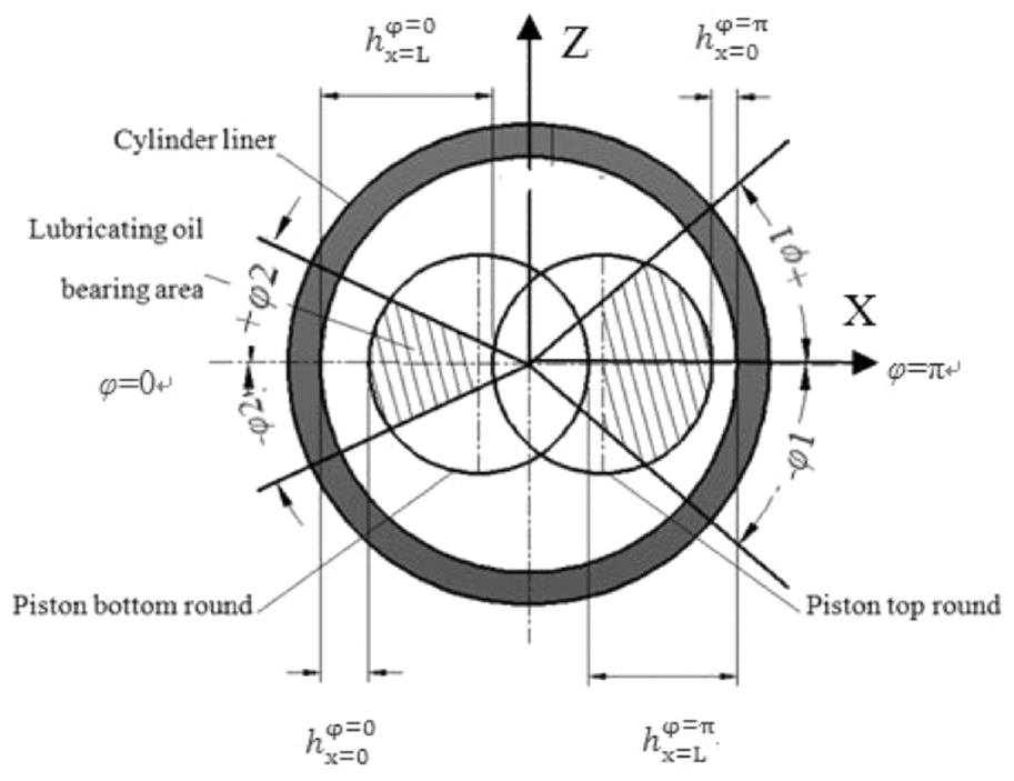
In this paper, an improved surface lubrication equation based on stochastic theory is used to analyze the hydrodynamic pressure on the skirt surface. During the second-order swing of the piston, due to the yaw angle of the primary and secondary thrust surfaces at a certain moment, the oil film thickness between the skirt and the inner wall of the cylinder will be different, resulting in boundary lubrication (as shown in Figure 9), so mixed lubrication should be considered at this moment.
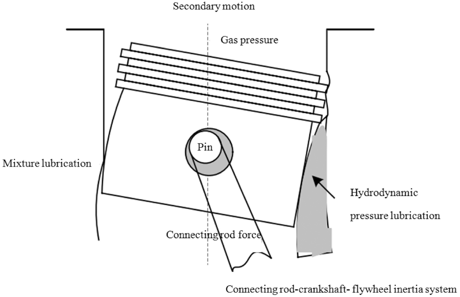
Lubrication diagram of piston skirt.
Oil film pressure calculation
Patir and Cheng42,43 studied the spatial lubrication of incompressible fluid on non-absolutely smooth surface at constant temperature, and deduced the average flow equation. Based on this, the average Reynolds equation was obtained by combining Reynolds equation. In this paper, the average Reynolds equation is used to deduce the hydrodynamic pressure between piston skirt and cylinder. According to the principle of relative motion, the cylinder is set as a fixed body, and the average Reynolds equation is as follows:

where, y is piston displaces in the y direction, z is piston displaces in the z direction, show in Figure 14, mm.
t is time, s.
The parameter distribution is shown in Figure 10.

Schematic diagram of oil film thickness.
When there is no contact between the two friction surfaces.
The pressure-flow factor is the average flow rate of lubricating oil on the rough surface than the average flow rate of lubricating oil on the smooth surface on the equal area microelement substrate, and its expression is44–46 after empirical transformation:


Shear flow factor is only produced during lubrication between rough surfaces. As a part of the lubricating oil is carried away by the waves on the rough surface during the relative sliding process, a formula for calculating the shear flow factor is proposed, that is the average flow rate of lubricating oil on the rough surface divides the average flow rate of lubricating oil on the smooth surface on the equal area microelement substrate.47–49

Calculation of oil film thickness
The boundary conditions of the mean Reynolds equation are:

Where L is the length of piston skirt, mm;
The parameter distribution is shown in Figure 11.
Schematic diagram of piston-cylinder liner lubrication.
Through the second-order swing of the piston, the following equations for solving the average oil film thickness between the piston skirt and the cylinder

Where C is the cold cylinder clearance between piston skirt and cylinder, mm;
Cold clearance C between piston and cylinder liner
Cold cylinder clearance C is not only the design requirement of fit tolerance in engineering installation, but also the working requirement of sliding friction pair between internal combustion engine and piston. In general, the reserved cylinder clearance for second-order swing design is 0.0008–0.0015 D, and D is the inner diameter of cylinder liner. For a given model, the cold cylinder clearance is a fixed value. 52
Calculation of contour function of piston skirt
The contour function of piston skirt generally includes two functions: transverse contour and longitudinal contour. Its design is mainly to improve the skirt deformation and lubrication under high temperature and high pressure. The transverse profile of piston skirt is designed to be oval in order to match the eccentric design of pin shaft and prevent the piston from dying suddenly during work. The fitted formula

Where G is ellipticity;
For general gasoline engines, the secondary correction coefficients
Longitudinal profile of piston skirt, in order to ensure that the piston can still keep cylindrical shape under high temperature working condition, so that the lubricating oil supply is not affected. The piston skirt is generally designed with a diameter gradually decreasing from the bottom end to the top end of the skirt, and the lower part of the middle of the skirt is designed with a convex form (as shown in Figure 12). The middle convex longitudinal profile is generally divided into three parts, namely, the upper slope section, the middle convex point, and the lower slope section.
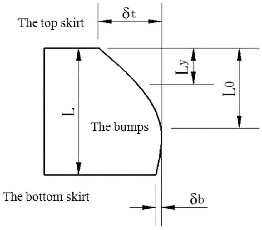
Longitudinal profile of piston skirt.
The fitting methods of skirt longitudinal profile mainly include ellipse fitting method, parabola fitting method, circle curve fitting method, and exponential equation fitting method. In this paper, parabola is selected for fitting. Because the upper end of the skirt is closest to the combustion chamber, the temperature is the highest and the thermal deformation is the largest, so the cubic parabola is selected to design the profile above the middle bump. Choose quadratic parabola to design the profile below the middle bump, and the expression is as follow:


where,
Ly is vertical distance from the top of a skirt to a point y on the contour of the skirt, mm.
Calculation of fit clearance function
.
54
When piston and cylinder liner work at high temperature, the deformation of skirt and cylinder liner causes the change of fit clearance, which is composed of the following parts.

where,
It is generally believed that the temperature of piston and cylinder liner is constant after the internal combustion engine works to a stable state, so the thermal deformation produced is also a fixed value. Just like
In order to calculate the average lubricating oil film thickness between the skirt and the cylinder liner more accurately, this paper intends to solve the average deformation of the skirt participating in the contact lubrication force area. The deformation values of each typical position of skirt involved in lubrication are extracted in matrix form. If N = 15 positions are taken, the deformation matrix caused by unit load is obtained. The thermal-mechanical coupling deformation results of each node in the matrix are listed in a single column, and the average deformation is obtained by 5 × 3 calculating the average value.

Where,
Calculation of average shear stress and friction of piston skirt
Hydrodynamic pressure will be generated in the squeezed lubricating oil film. The average hydrodynamic pressure of lubricating oil film
Calculation of normal pressure
Where in the skirt normal pressure

Where R is piston radius, mm;
S is the pressure bearing area of the lubricating oil film between the skirt and the cylinder liner, mm2.
The shearing stress τ is calculated
The shear stress

where,


Calculation of friction force
The friction force

Lubrication simulation analysis of standard piston and bionic piston
The bionic piston designed in this paper is to achieve the effects of drag reduction, wear resistance, moistening, and consumption reduction without changing the shape and structure of piston skirt. The realization of these indexes undoubtedly comes down to reducing the friction of piston skirt.55,56 In this paper, the oil film thickness, hydrodynamic pressure, shear force, friction force, and fluid dynamic pressure of standard and bionic piston skirt are analyzed in detail by means of average Reynolds equation. Because of the large amount of data and the consistent motion process of both standard and bionic pistons in the whole four-stroke of internal combustion engine, that is, the comparative research trend at each time point is similar, only the instantaneous time point of the worst working condition of piston skirt is solved and analyzed.
It is proved by research that,57,58 assuming that the crankshaft rotation angle 0° is the beginning of the intake stroke, then the crankshaft rotation angle between 360° and 540° are in the power stroke. Due to the eccentric design of piston pin and the fit clearance between piston skirt and cylinder, when the crankshaft moves to 390°, the movement caused by the second-order swing makes the main thrust surface of the skirt closest to the inner wall of the cylinder. At this time, the lubricating oil film is thinnest, the hydrodynamic pressure is maximum, and the friction force is maximum. Therefore, the piston skirt state at this time point under the normal working speed of the crankshaft is selected for experimental analysis and research.
The relevant parameters required for calculating the average Reynolds equation of piston are shown in Table 4.
Related parameters of piston.

Because the deformation of piston skirt directly affects the thickness of lubricating oil film, which is the main calculation factor of lubricating oil hydrodynamic pressure, the calculation of normal pressure load, shear force, friction force, and fluid dynamic pressure of piston skirt are closely related to it.59,60 In this paper, the macroscopic lubrication mechanism of bionic piston will be analyzed from the whole average deformation and local average deformation of piston skirt.
The design of the groove on the skirt surface, because its shape is consistent with the flow direction of lubricating oil, has been proved by research 61 in this case, the flow rate of lubricating oil in the groove will slow down. And storing lubricating oil in the oil-rich state and supplying lubricating oil through cavities and hydrodynamic pressure in the oil-deficient state. The lubrication analysis of the overall macro fit of the whole skirt and groove will be carried out below.
Analysis on the comparison of average oil film thickness
Due to the design of piston axial convex profile and the large temperature difference between the top and bottom of piston in temperature arrangement, the gas impact force acting on the top of piston will inevitably lead to the inconsistent deformation of the top, middle, and bottom of piston. The average deformation of the whole skirt can not fully reflect the local characteristics. Although the size of the bionic groove in this design is the same at the upper and lower ends of the skirt, in order to verify that it will not increase the load on the skirt locally, but will improve the lubrication conditions. Lubrication analysis will be made on the top, middle, and bottom ends of the bionic groove piston skirt.
The average lubricating oil film thickness of standard piston skirt is 0.0779 mm. Compared with Figure 13, the average thickness of skirt oil film is No.3, No.9, No.7, and No.4 bionic pistons. Narrow groove shape between wide grooves is most beneficial to increase the average oil film thickness and reduce the average deformation of skirt, which shows that the design of grooves along the axial direction is better than that of through-hole unloading to disperse the concentrated stress of skirt.

Comparison diagram of average oil film thickness of bionic grooved piston skirt.
The average lubricating oil film thickness at the top of standard piston skirt is 0.0908 mm. Compared with Figure 13, the average lubricating oil film thickness at the top of bionic piston skirt is increased by 50% compared with that of standard piston, and the average deformation at the top of bionic piston skirt is reduced by 21% compared with that of standard piston. Because of the existence of piston ring, the top of the skirt is not too close to the inner wall of the cylinder, so the oil film thickness at the top of the bionic piston skirt is less than the overall situation of the piston skirt. Because of the high temperature at the upper end of the piston skirt, the bionic shape disperses the concentrated heat well, and the average deformation reduction at the top of the skirt is similar to the overall average deformation of the skirt. No.1, No.7, No.9, and No.2 bionic pistons are better at the average thickness of oil film at the top of skirt.
The average lubricating oil film thickness in the middle of standard piston skirt is 0.0898 mm. Compared with Figure 13, the average lubricating oil film thickness in the middle of bionic piston skirt is larger than that of standard piston, the average lubricating oil film thickness in the middle of bionic piston skirt is increased by 50% compared with that of standard piston, and the average deformation in the middle of bionic piston skirt is reduced by 19% compared with that of standard piston. Because of the design of axial convex profile, the middle part of the skirt belongs to the part closest to the inner wall of the cylinder, and its deformation is more limited. Therefore, the increase of oil film thickness in the middle part of bionic piston skirt is less than that of the whole piston skirt. However, the bionic shape design evenly arranged here and running through the skirt makes the thermal-mechanical coupling deformation smoothly transition from the top of the skirt at higher temperature to the bottom of the skirt with thinner material thickness. No.3, No.2, No.9, and No.5 bionic pistons are better at the average thickness of oil film in the middle of skirt.
The average lubricating oil film thickness at the bottom of standard piston skirt is 0.0531 mm. Compared with Figure 13, the average lubricating oil film thickness at the bottom end of bionic piston skirt is increased by 133% compared with that of standard piston, and the average deformation at the bottom end of bionic piston skirt is reduced by 26% compared with that of standard piston. The thin wall thickness at the bottom of the skirt makes it easy to deform, and the second-order deflection of the piston makes it the much easiest to knock on the cylinder. The groove shapes bionic design improves these disadvantages at the bottom of the skirt, so the oil film thickness and deformation at the bottom of the bionic piston skirt are far better than the overall situation of the standard piston skirt. No.2, No.4, No.7, and No.9 bionic pistons are better at the average thickness of oil film at the bottom of skirt.
Analysis on the contrast of oil film bearing area
The overall oil film pressure area of the standard piston is 1099 mm2. Comparing with Figure 14, the overall oil film pressure area of all bionic piston skirts is smaller than that of standard pistons, and the design of bionic shape in piston skirts will undoubtedly lead to the reduction of oil film pressure area, thus affecting the normal force and friction force of skirts related to oil film pressure area. Later, when discussing these two forces, they will be analyzed in combination with the pressure area of oil film.

Comparison diagram of oil film bearing area of bionic grooved piston skirt.
Analysis of normal force comparison
The skirt normal force of the standard piston is 1450 N. Comparing with Figure 15, the average normal force of bionic piston skirts are reduced by 71% compared with that of standard pistons. Normal force of No.9, No.8, No.2, No.7 bionic piston skirt are smaller. That can be seen that the oil film force area is 800–940 mm2, hydrodynamic pressure below 1.125 MPa bionic piston skirt normal force is smaller.
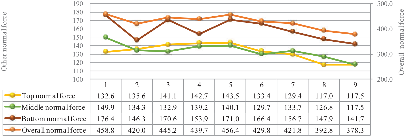
Comparison of normal force of bionic grooved piston skirt.
The skirt normal force at the top of the standard piston is 352 N. Comparing with Figure 15, the average skirt top normal force of bionic pistons are reduced by nearly 62% compared with that of standard pistons. Normal force of No.8, No.9, No.7, No.1 bionic piston skirt are smaller. That can be seen that the oil film force area is slightly smaller than 74%–87% of the standard piston bionic piston, and when the oil film thickness is less than 0.137 mm, the skirt top normal force is smaller.
The skirt normal force in the middle of the standard piston is 360 N. Comparing with Figure 15, the average skirt middle normal force of bionic pistons are reduced by nearly 63% compared with that of standard pistons. Normal force of No.9, No.8, No.6, No.3 bionic piston skirt are smaller. That can be seen the oil film force area accounts for 74%–82% of the bionic piston skirt area, and middle normal force is smaller.
The skirt normal force at the bottom of the standard piston is 1029.6 N. Comparing with Figure 15, the average normal force at the skirt of bionic pistons are reduced by nearly 85% compared with that of standard pistons. No.9, No.2, No.8, No.4 bionic piston skirt normal force are smaller. That can be seen that the oil film thickness is greater than 0.120 mm, make the oil film force area smaller and bionic piston skirt normal force smaller.
Analysis of shear force contrast
The shear force of standard piston skirt is 0.212 N, and comparing with Figure 16, the shear force of bionic piston is reduced by 41% on average compared with that of standard piston. The shear force at the top of standard piston skirt is 0.182 N, and comparing with Figure 16, the shear force of bionic piston is reduced by 33% on average compared with that of standard piston. The shear force in the middle of standard piston skirt is 0.184 N, and comparing with Figure 16, the shear force of bionic piston is reduced by 34% on average compared with that of standard piston. The shear force at the bottom of standard piston skirt is 0.311 N, and comparing with Figure 16, the shear force of bionic piston is reduced by 67% on average compared with that of standard piston. The average oil film thickness of piston skirt still has a great influence on shear force, and the change of shear force of bionic piston is equivalent to the change of oil film thickness.
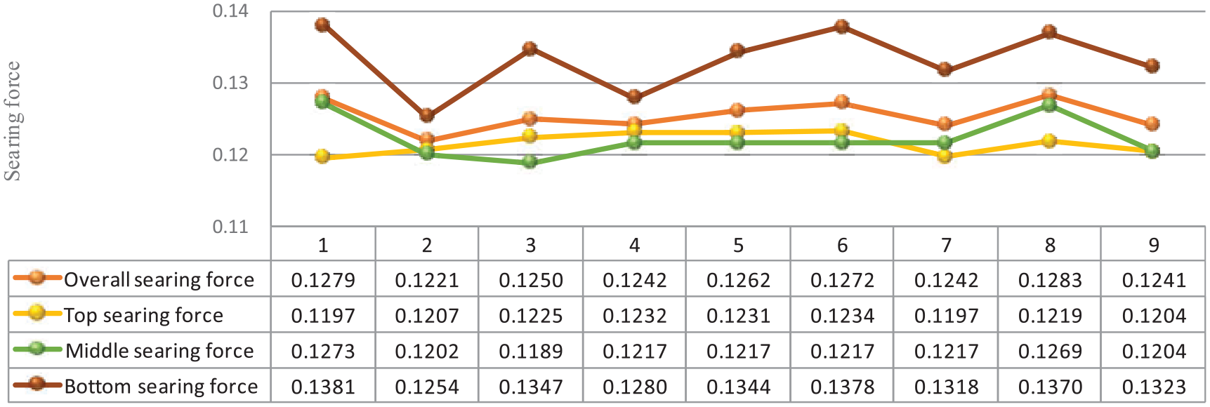
Searing force comparison diagram of bionic grooved piston skirt.
Analysis of friction contrast
The friction force of standard piston skirt is 23.5 N, and comparing with Figure 17, the overall friction force of bionic piston skirt is less than that of standard piston, and reduced by 50%. No.9, No.8, No.6, and No.7 bionic pistons have smaller skirt friction. When the pressure-bearing area of bionic piston skirt is 74%–85% of the pressure-bearing area of standard piston, the friction is the smallest. When the pressure-bearing area of bionic piston skirt is about 89% of the pressure-bearing area of standard piston, the friction force is larger. Narrow groove between wide grooves is still the best design, followed by groove shapes arrangement.

Friction comparison diagram of bionic grooved piston skirt.
The friction force at the top of standard piston skirt is 6.67 N, and comparing with Figure 17, the friction force at the top of the skirt of bionic piston is less than that of standard piston, and reduced by 44%. No.8, No.9, No.7, and No.6 bionic pistons have smaller skirt friction. When the pressure-bearing area of bionic piston skirt is 75%–85% of the pressure-bearing area of standard piston, the friction is the smallest. When the pressure area of bionic piston skirt is 88%–89% of the pressure area of standard piston, the friction force is the largest.
The friction force in the middle of standard piston skirt is 6.74 N, and comparing with Figure 17, the friction force in the skirt of bionic piston is less than that of standard piston, and reduced by 44%. No.9, No.8, No.6, and No.7 bionic pistons have smaller skirt friction. When the pressure-bearing area of bionic piston skirt is 74%–82% of the pressure-bearing area of standard piston, the friction is the smallest. When the pressure area of bionic piston skirt is 87%–89% of the pressure area of standard piston, and the shear force is large, the friction force is maximum.
The friction force in the bottom of standard piston skirt is 11.39 N, and comparing with Figure 17, the friction force at the bottom of the skirt of bionic piston is less than that of standard piston, and reduced by 64%. No.9, No.8, No.2, and No.7 bionic pistons have smaller skirt friction. When the pressure-bearing area of bionic piston skirt is 74%–85% of the pressure-bearing area of standard piston, the friction is the smallest. When the pressure area of bionic piston skirt is 88%–89% of the pressure area of standard piston, the friction force is the largest.
Analysis of fluid dynamic pressure
The physical significance of the mean Reynolds equation is to decompose instantaneous parameters into time averages, which are represented by turbulent motion equations with average quantities. The fluid dynamic pressure can be finally calculated by the relevant parameters determined in equation (1), that is
The standard piston fluid dynamic pressure is 3.265 MPa. Figure 18 shows the dynamic pressure of all bionic piston fluids. It can be seen that the dynamic pressure of all bionic piston fluids is lower than that of standard piston, indicating that the lubrication effect of bionic piston is better than that of standard piston. The fluid dynamic pressure of the bionic piston is 33%–36% of that of the standard piston, indicating that the lubrication effect of the bionic piston is greatly improved. No.2, No.4, No.7, and No.9 bionic pistons have smaller fluid dynamic pressures. It proves that the bionic piston with wide groove and narrow groove, the width of the wide groove is 0.8 mm, and the spacing is 10°, make lubrication to the best.

Fluid dynamic pressure of bionic grooved piston skirt.
Durability test of internal combustion engine
There are many kinds of bench tests for internal combustion engine performance verification. Because of the different research emphasis, the design and construction of the test bench are quite different. The above-mentioned research on the performance of internal combustion engine piston with bionic shape based on theoretical and simulation analysis needs experimental data for live verification. Because the design of bionic shape in this study is to improve the fatigue life of piston and prevent piston fatigue failure from the angle of drag reduction and wear resistance, it is proposed to carry out bench durability test on bionic piston and standard piston of internal combustion engine. The test matrix is a mature internal combustion engine, so the data collection of internal combustion engine durability test only focuses on piston performance.
Design of test bed
In this study, the performance index of bionic piston under actual working conditions is verified by bench test of internal combustion engine. The objective of this study is to improve the interfacial lubrication conditions of piston-cylinder friction system, solve the friction and wear problem of piston cylinder liner system. The bionic piston can achieve multiple effects of drag reduction, wear resistance, energy saving, and emission reduction. Therefore, when designing the test-bed, on the one hand, it is necessary to test the reliability of the whole internal combustion engine and observe the influence of the improvement of piston skirt shape on the working performance of the whole internal combustion engine. On the other hand, it is necessary to consider the wear and heat dissipation of the piston.
In the durability bench test of the whole engine, the test scheme should be formulated strictly according to the national standard, including test requirements, test condition control, adjustment and setting of accessories and systems of the engine during the test, test procedures, reliability test specifications, inspection and maintenance, and arrangement of test results, so as to obtain detailed and reliable test results. In this project, an internal combustion engine cold test-bed has been set up in the Key Laboratory of Engineering Bionics, Ministry of Education, Jilin University (as shown in Figure 19).
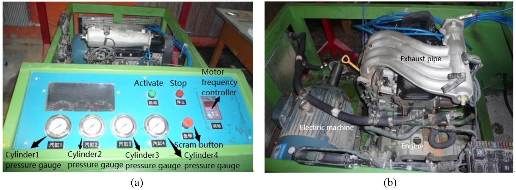
Test bench: (a) test bench and (b) internal combustion engine.
The motor is used to drive the flywheel to realize the reciprocating movement of the piston in the cylinder. The input power is at the crankshaft and the output power is at the cylinder. The output power is determined by detecting the maximum pressure of the compressed gas in each cylinder. The electronic control system in the internal combustion engine is completely canceled, the cooling water channel circulates normally, and the lubrication, intake and exhaust systems are all opened. According to the run-in specification run-in 20 h run-in speed is idle 800 r/min, not included in the durability test time. Water-cooled oil temperature control below 363 K (90°C). The coolant temperature remains below 353 ± 5 K (80°C ± 5°C).The durability test time is 500–1000 h, due to the cold experimental characteristics of this experiment, choose 700 h, crankshaft choose the normal speed of 3200 r/min.
Test methods for durability of internal combustion engines
The LX108 internal combustion engine used in the test is in-line four cylinders, and every disassembly and assembly of the internal combustion engine will produce certain installation errors. In order to compare the standard piston with the bionic piston more accurately, a standard piston is placed among the four pistons in each test.62–64
(1) In order to calculate the amount of piston wear, the piston should be weighed before installing a new tested piston every time, and the same is true after the test.
(2) During the test process, ensure that the test space is at normal room temperature of 20°C, the humidity of the surrounding environment is suitable, the air quality is normal, PM2.5 is below 200, and the air pressure range is 0.9–1.1 atmospheres.
(3) After the initial startup observation of the test bench for 0.5 h, check whether the cylinder pressure is stable and normal and whether there are other mechanical faults every 1 h when it runs stably. Ensure that the whole test conditions are basically consistent and no sudden special conditions occur.
(4) The thermal imager is used to detect the top temperature of the piston in different periods after the internal combustion engine works stably, so as to compare and study the efficiency of bionic piston in heat dissipation.
(5) After the test, the bionic and standard piston skirt surface condition is detected. Because the wear amount is very small, the roughness measuring instrument is used for sampling and analysis.
Selection of piston for test
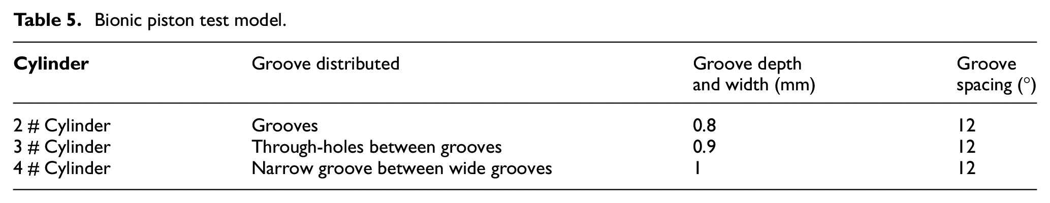
Because of the long period of durability bench test, this study will not carry out bench test on all bionic piston models designed above, but only select three bionic pistons with the best structure and standard pistons in each bionic design for bench test (see Table 5 for piston test models). In the test, standard pistons were placed on No.1 cylinder, and bionic pistons were placed on the other three cylinders.
Bionic piston test model.
Analysis of test results
During the piston movement, friction and wear occur on the skirt surfaces distributed on both sides of the pin hole. However, due to the eccentric design of the piston pin hole, the main thrust surface bears more force and the test effect is more obvious during the piston movement, so the data in this section are collected for the main thrust surface. Firstly, the main thrust surface of piston skirt before and after the test was photographed and compared to observe the drag reduction, wear resistance, and moisture increase performance of bionic piston superior to standard piston, as shown in Figure 20 for details.

Comparison before and after piston test: (a) before test 1 # cylinder standard piston, (b) after test 1 # cylinder standard piston, (c) before test 2 # cylinder bionic piston, (d) after test 2 # cylinder bionic piston, (e) before test 3 # cylinder bionic piston, (f) after test 3 # cylinder bionic piston, (g) before test 4 # cylinder bionic piston, and (h) after test 4 # cylinder bionic piston.
As can be seen from Figure 20, the piston wear after the test is small, and the surface wear of bionic and standard pistons cannot be accurately detected by the usual macroscopic profile measurement method. Here, the method of detecting microscopic roughness is used for sampling analysis.
Piston contour detection before the test, wave distance is less than 1 mm, bionic piston and standard piston test results before the difference is not much, there is not much value for analysis. Therefore, this paper only lists the contour detection results of bionic piston and standard piston after the test for comparative analysis. As bionic form is the source of drag reduction, wear resistance, and moisture enhancement. Therefore, the wear around the bionic shape can best show their superior effects. The following roughness profiler is used to detect the positions around the bionic shape, and every detection of the bionic shape samples the standard piston correspondingly, so as to minimize the error of the detection results. The stress and strain of standard piston and bionic piston skirt are concentrated in the middle position, and the smaller the sampling length of high-precision roughness profiler, the more accurate the measurement results are.
See Figure 21 and Table 6 for the detection position of the test piston, and the solid blue line in the figure is the sampling detection position. Because of the particularity of bionic piston design, the detection positions are arranged on both sides of the middle groove in the circumferential direction of the skirt, so the same position is detected twice, once on the left side of the groove and once on the right side of the groove. Because the piston is designed symmetrically here, the test result is the average value of the test values on both sides. Detected results are shown in Figure 22.

Explanatory diagram of piston profile detection position: (a) 1 # cylinder standard piston, (b) 2 # cylinder bionic piston, (c) 3 # cylinder bionic piston, and (d) 4 # cylinder bionic piston.
Description of piston sampling position.


Ra detection trend chart of test piston.
Sampling parameters are set, and the sampling length is 0.25 mm. Roughness measurement: curved surface. Measuring range: −0.25 to 0.25 mm. Stylus radius: 2 μm. Length of rod: 50,000 μm. The sampling positions of the second group of test pistons are the same, and the distance from each sampling position to the bottom edge of the piston is shown in Table 6.
Compared with the arithmetic average deviation Ra of bionic vertical groove piston profile, the following conclusions are drawn (as shown in Figure 22).
(1) Only by observing the roughness index of the standard piston, it can be seen that the overall wear of the standard piston fluctuates greatly, with the largest wear part at the bottom of the skirt, the common wear part at the middle of the skirt, and the smallest wear part at the upper end of the skirt.
(2) Comparison between bionic piston in 2 # cylinder and standard piston. The overall wear resistance of bionic piston is higher than that of standard piston, and its wear degree distribution is uniform. The maximum wear position is located in the middle of piston skirt, and the minimum wear position is at the top of skirt. Bionic groove makes the overall wear trend of skirt similar to that of standard piston, but it is more stable. The design of groove penetrating the skirt can not only store oil and chips, but also reduce the thermal deformation of the skirt, increase the oil film thickness and reduce the probability of knocking on the bionic piston skirt.
(3) Comparison between bionic piston in 3 # cylinder and standard piston. The overall wear resistance of the bionic piston is higher than that of the standard piston. The overall wear condition of the bionic piston is the most uniform, and its wear trend is opposite to that of the standard piston, with the minimum wear at the bottom of the skirt and the maximum wear at the top of the skirt. It shows that the bionic groove can increase the oil film thickness at the bottom of the skirt.
(4) Comparison between bionic piston in 4 # cylinder and standard piston. The overall wear resistance of bionic piston is higher than that of standard piston, and the wear at the bottom and top of bionic piston skirt is less, while the wear in the middle of skirt is greater, and the overall fluctuation is more severe. Narrow grooves between wide grooves can increase the burden on skirt and weaken its stiffness. However, its multi-groove design stores more lubricating oil for the skirt, which makes the bottom and top of the skirt wear less.
(5) Comparing the wear of three bionic pistons, the wear of piston skirt of 2 # cylinder is the best, and the groove shapes arrangement can better prolong the service life of piston. The wear trend of piston skirt of 3 # cylinder is the most stable, which shows that the uniform and non-tight through-holes in the through-holes between grooves further play the role of oil storage, chip storage, and accelerating the flow and heat dissipation of lubricating oil. The wear trend of piston skirt of 4 # cylinder fluctuates the most, and the wear in the middle of the skirt is the most serious. Although the narrow groove between wide grooves stores more lubricating oil for the skirt, considering the overall situation comprehensively, the factors affecting the wear and life of the skirt are not only the oil film thickness.
Conclusion
(1) For the bionic groove piston, the thickness of oil film on the skirt is thicker when the groove width is 0.8 mm and the spacing is 10°. This time the bionic piston lubrication is also the best.
(2) The bionic piston with the oil film bearing area accounted for 74%–87% of the standard piston has the least normal pressure.
(3) The oil film bearing area of the bionic piston accounted for 74%–85% of the standard piston, and the friction is the least.
(4) The upper end of the skirt is arranged with groove shapes, and the lower end is arranged with narrow groove between wide grooves, and the lubrication effect is better.
Footnotes
Acknowledgements
Thanks to the Key Laboratory of Engineering Bionics, Ministry of Education, Jilin University for providing experimental equipment and venues. Thanks to Changchun Institute of Technology for providing a soft environment for scientific research.
Handling Editor: Chenhui Liang
Declaration of conflicting interests
The author(s) declared no potential conflicts of interest with respect to the research, authorship, and/or publication of this article.
Funding
The author(s) disclosed receipt of the following financial support for the research, authorship, and/or publication of this article: Thanks to the following funds for their support: the “Thirteenth Five-Year Plan” Science and Technology Project of Jilin Provincial Department of Education (Project Name: Adhesive Friction Mechanism of Animal Foot Pad and Its Bionic Optimization Design in Brake Friction Increasing and Life Prolonging Function, No. JJKH20180982KJ); Jilin Province higher education teaching reform research project (Project Name: Research on undergraduate teaching reform based on the comparison between Chinese and English higher education and the individual development of college students, No. JLJY202147435961); Scientific research project of Jilin Provincial Development and Reform Commission (Project Name: Study on charging system and application of Volatile organic gas in passenger vehicle interior based on volume increment method, No. 2017c048-43); Jilin Province Higher Education Research Project (Research on Cross-discipline Teacher Construction and Assessment Mechanism under the Mode of International Talent Training, No. JGJX2022C88); Jilin Province Vocational Teaching Research and Adult Education Teaching Reform Research project (Vocational Students Craftsman Competition Training Path Research and Practice, No. 2021ZY306); Jilin Province Education Science Planning Project (Research on the cultivation mode of “learning, teaching and research” under the background of “New Engineering,” No.2023).