
Abstract
Measurements of piston skirt film thickness in-recoprocare are relatively scarce and generally require significant modification to a test engine. However, the trend of engine original equipment manufacturers to downsize capacities whilst maintaining power outputs, increases the demands placed on the piston components. As a result, the relative pressure loading on the piston skirt is increasing and requires that lubrication be optimised to maintain low friction. This paper outlines experimental skirt film thickness measurements obtained from a fired single cylinder engine using reflected ultrasound. The profile of the film structure is observed and an insight into some of the motions of the piston can be determined. This study shows that quantitative film thickness measurements can be made using ultrasound and which are comparable with other established techniques.
Introduction
Understanding the lubrication processes occurring at the piston–cylinder interface of IC engines is of key importance to improve both associated parasitic frictional losses and oil consumption, which directly affect efficiency and emissions. Refined numerical codes are increasingly being sought to model conditions in both the ring pack and skirt contacts. However, the relative flexibility of the skirt generates a complex situation in which body forces, thermal loading and pressure forces combine to influence the lubrication conditions. Experimental validation remains a crucial step in appraising such numerical models.
The hostile conditions of an engine (vibration, temperatures, inertial loading, etc.) present a significant challenge to the investigator. A number of techniques have been used to measure the skirt film thickness, but implementation generally requires significant modification to the engine. For cylinder-based measurements, penetration of the bore surface is required to install sensors. For piston-based measurements a suitable linkage or telemetry system is required to route the measurement signals out of the engine. Laser-induced fluorescence (LIF) has been used most widely to measure skirt oil film thickness. The intensity of fluorescence of a doped oil, when energised at a specific wavelength of light is calibrated against film thickness. LIF has been used to obtain both single point measurements with cylinder mounted fibre optics honed to match the bore and in full-field configurations using optical cylinders.1,2 Eddy current methods have been used to obtain piston-based measurements by mounting sensors directly into the upper and lower portions of the skirt. 3 Simultaneous measurements on both the thrust and anti-thrust provided a means to infer piston orientation within the cylinder.
In this paper, ultrasound is used to measure lubricant film thickness along the centreline of the skirt on both the thrust and anti-thrust surfaces of a single cylinder test engine. Test runs were performed in both motored and fired configurations, the differing thermal and loading conditions providing significantly different lubrication conditions. Crucially, the measurements were carried out without requiring cylinder penetration, minimising their influence on the function of the engine.
Materials and methods
Test engine
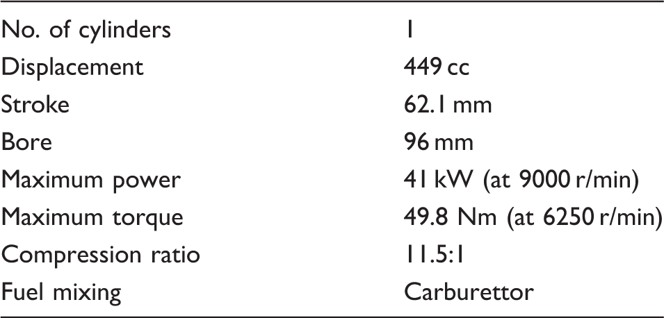
Selected Honda CRF450R engine specifications.
Ultrasonic instrumentation
The ultrasonic pulses used to measure the condition of the oil film were both generated and received using a series of piezoelectric elements mounted axially down the exterior surface of the cylinder within the water-jacket as shown in Figure 1. The transducers were cut from disc-shaped elements (nominally 10 MHz) to form 1 × 5 mm strips, giving improved spatial resolution. A flat was machined on the exterior surface of the cylinder, aligned to its central axis to mount the sensors. The spacing of the sensors down the length of the bore was not equal, optimised for improved spatial resolution around TDC during the measurement of compression ring oil film thickness. Despite this configuration, sensor density over the skirt was sufficient to obtain the lubricant film thickness profiles documented in this paper. The strips were rigidly bonded using a high temperature, low viscosity adhesive (Vishay M-Bond 610), capable of withstanding a prolonged surface temperature of 250 ℃. The elements themselves being formed from lead–zirconate–titaninate were rated to 360 ℃. Waterproofing was achieved using a high temperature epoxy resin (Scotch-Weld DP760) and wiring was routed out of the water jacket using a specially designed case.
Engine sensory instrumentation.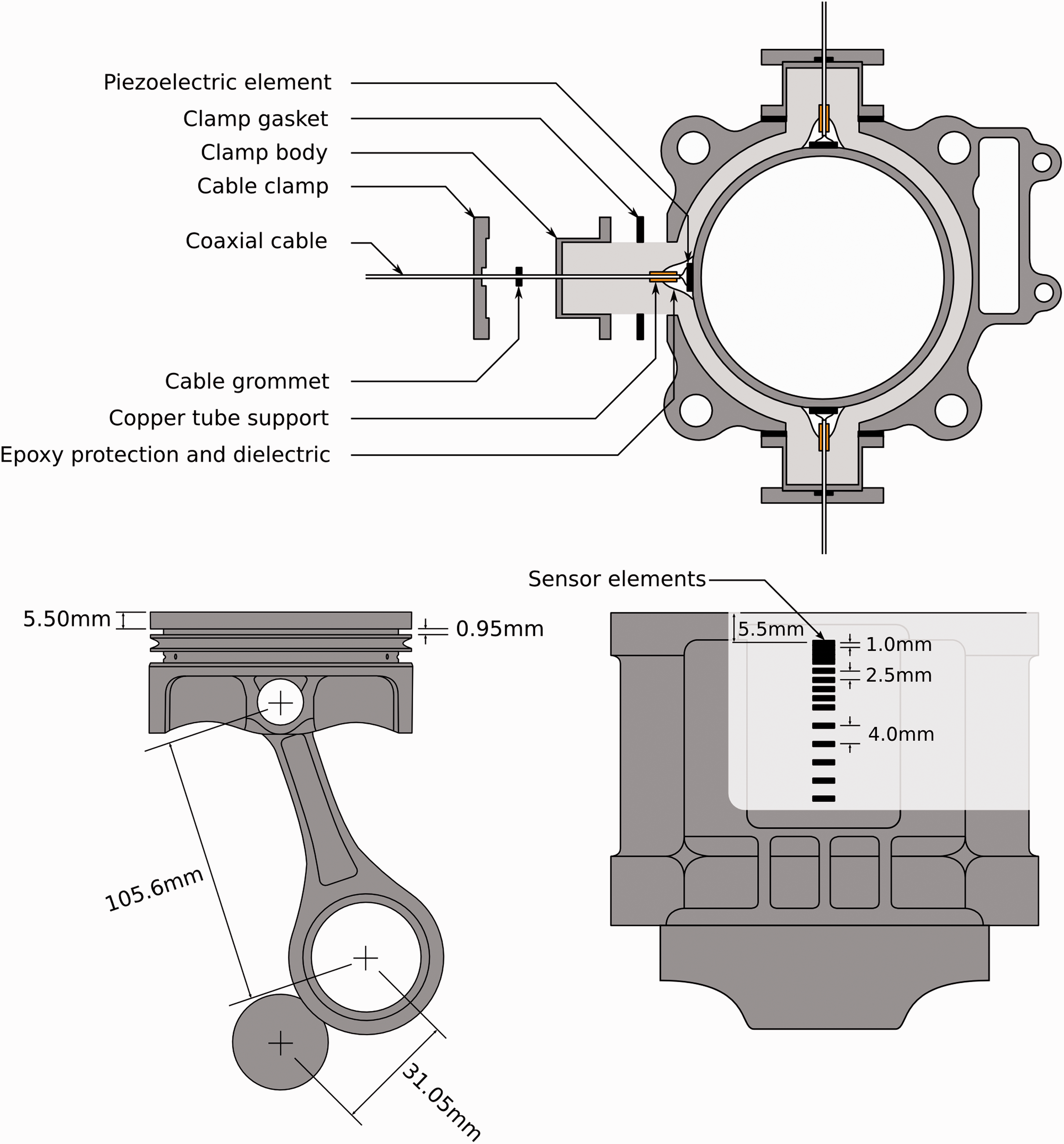
The system used to pulse and capture the ultrasonic signals consisted of two PCI cards; an ultrasonic pulser-receiver (UPR) and digitiser, mounted in a PC chassis and controlled using bespoke LabVIEW software. The system was configured to operate in a pulse-echo mode, whereby the same transducer was used to generate and detect the projected ultrasonic wave. A maximum capture rate of 80 kPulse/s was achieved and digitised at a rate of 100 MSamples/s.
Signal processing
The method of using ultrasound to measure fluid film thickness has been documented in a number of articles4–6 and a preliminary application of the technique to engine oil film measurements can be found in the study of Dwyer-Joyce et al. 7 and Mills et al. 8 A brief account of the processing steps follows, but the reader is directed to the aforementioned literature for greater depth. A material discontinuity (such as a tribological interface) will affect the propagation of an ultrasonic wave. If a wave strikes perpendicularly to a surface, a portion of its energy will be transmitted into the adjacent component, while the remainder will be reflected back towards the source of the wave. The stiffness of the contact, which, for a fluid film will depend upon its thickness and acoustic properties of it and the bounding materials, governs the reflection coefficient (R) and thus provides a means to measure film thickness if suitably characterised.
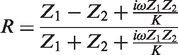
The complex quasi-static spring model proposed in Tattersall
9
is used as the basis for defining the proportion of ultrasonic pulse that is reflected from an imperfect interface (reflection coefficient, R) and is given in equation (1). The acoustic impedance of the bounding materials, Z, determine the basic response of an ‘ideal’ discontinuity; however, it is the interfacial stiffness K, which determines the deviation of the real contact as a result of the presence of a thin sandwiched layer (such as the case of a thin oil layer).
In this case, the stiffness of the fluid layer can be defined in terms of its bulk modulus, B, using equation (2)

This can be redefined in terms of the speed of sound, c, and density, ρ, of the fluid, which are more readily measurable, as in the following equation

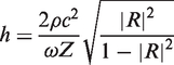
Combining equations (1) and (2) gives a relationship between film thickness and measured reflection coefficient amplitude as shown in equation (4). For this case where both skirt and cylinder were aluminium, acoustic impedances (Z1 and Z2) are identical
Engine component and lubricant acoustic properties.
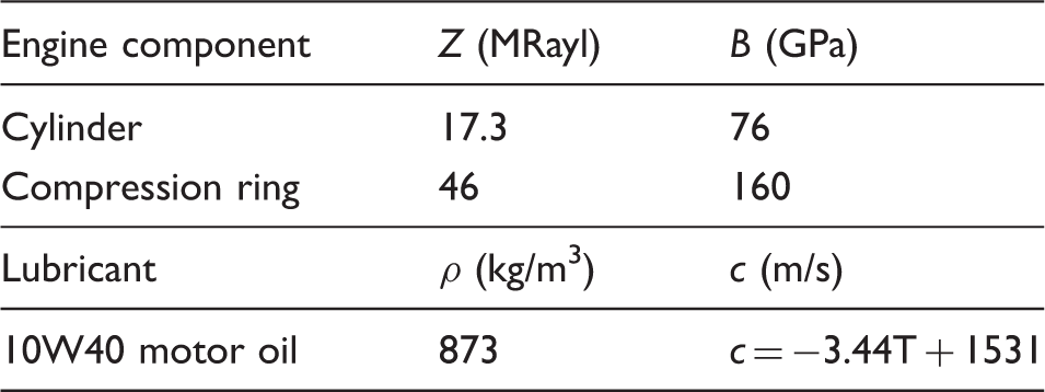
Figure 2 shows the signal processing steps schematically. Having isolated the reflection occurring from the cylinder/skirt junction, its spectral content is extracted using the fast Fourier transform and normalised using a reference reflection. The reference reflection was obtained whilst the piston was away from the measurement region; the cylinder/air interface causing total reflection. The motion of the piston enabled a reference local to each stroke to be captured, thus removing any changes in sensor response due to temperature.
Depiction of reflection occurring at skirt interface and subsequent processing steps carried out for each captured reflection.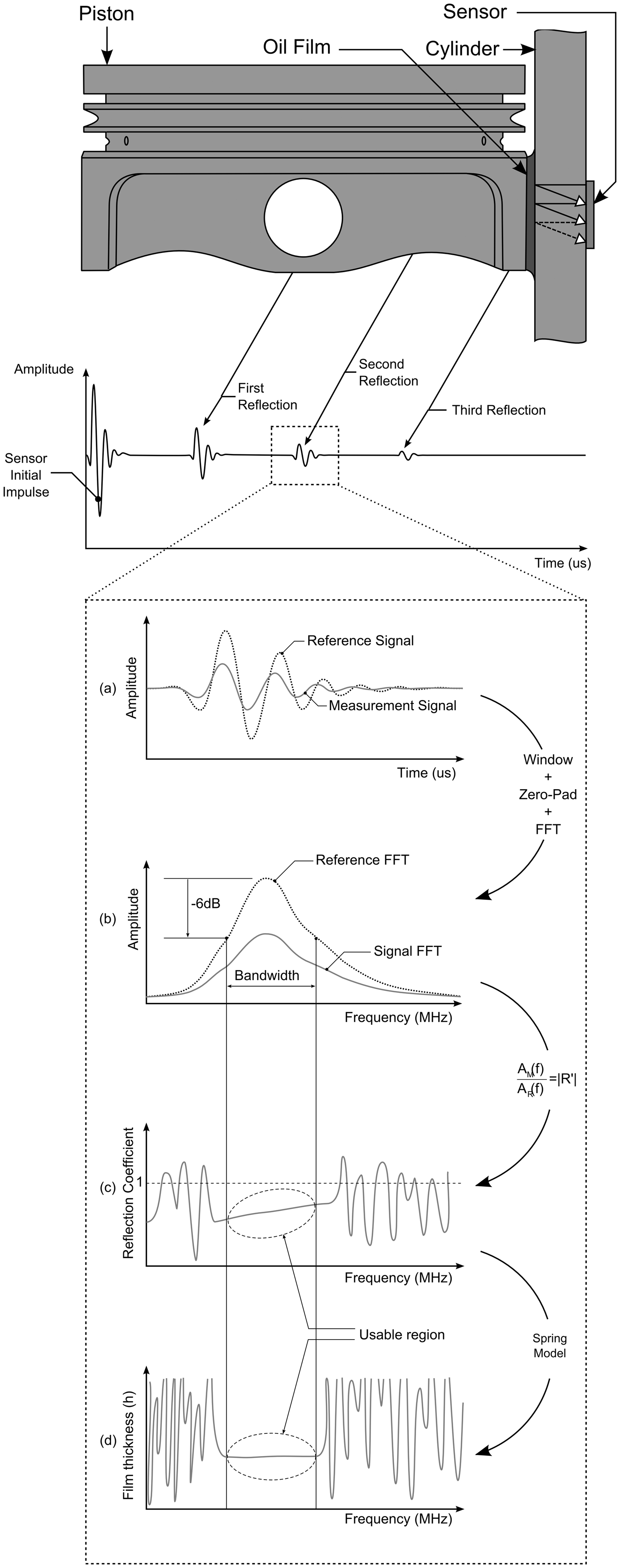
In most situations, the first reflection is analysed as it provides the largest signal to noise ratio. However, for this particular set up the second reflection was used owing to a technicality of the acquisition system in correlating crank position with the reflected signal. In interacting with the fluid film twice, the corresponding reflection coefficient R′ is equivalent to R2, and thus was substituted into equation (4).
Test conditions and measurements
Tests were carried out under motored and three fired conditions; no-load, 50% load and 90% load, at 4000 r/min. Though short, a finite time is required for the ultrasonic wave to fully reflect from the interface. The reflected waveform consisted of four defined oscillations at 10 MHz. This corresponded to a total film interaction time of 400 ns. At the peak piston speed of 13.5 m/s, the piston moved 5.4 µm during this interaction period and was therefore considered to be an instantaneous measurement. Given the engine speed, the resulting mean piston speed of 8.3 m/s was approximately similar to that of a gasoline passenger vehicle travelling at motorway speeds (engine speeds in the order of 2500 r/min to 3000 r/min).
Crank angle and TDC position were measured simultaneously alongside the ultrasonic signals to single degree resolution. Crank rotational speed was calculated and peak angular velocity (occurring during the expansions strokes) used as a marker to obtain the 720° reference frame.
In measuring crank angle, it was possible to map the film thickness measurements to the local position on the piston skirt surface given the geometry of the assembly (assumed to be rigid) and sensor location on the cylinder. Thus a series of film traces were constructed as the piston passed the active sensors.
Results and discussion
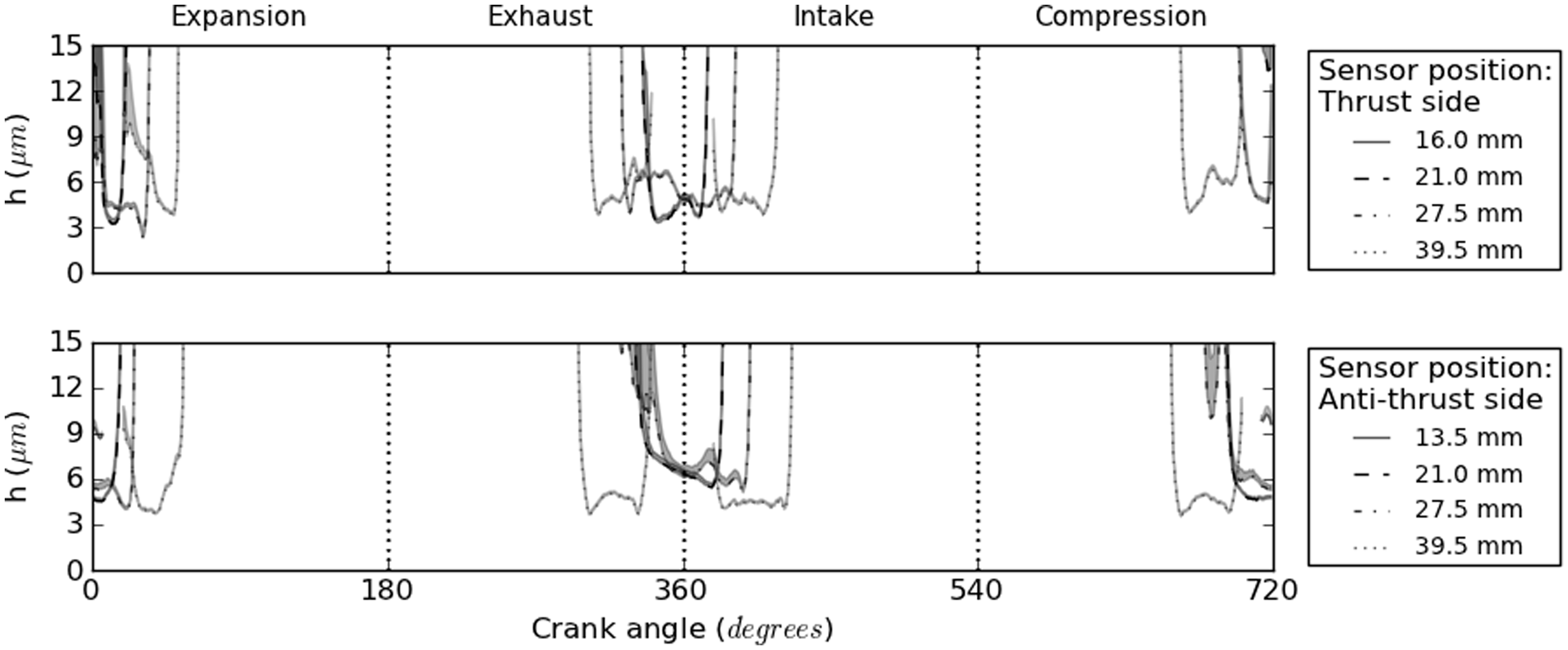
Figures 3 and 4 show the processed film thickness measurements for both the thrust and anti-thrust surfaces during motoring and fired conditions for a fixed engine speed of 4000 r/min. Each trace corresponds to a different sensor location down the length of the barrel and represents the average film measured over a total of approximately 65 cycles. The shaded region provides the limit of the first standard deviation boundary to provide an indication of cycle–cycle variations. Film thickness variability was lowest for the fired case, particularly towards the centre stroke positions. This indicates relatively stable piston dynamics, with repeatable secondary motions and deformation of the piston–con–rod assembly. Larger deviations during the motored case point towards increased clearance, giving rise to greater variability in film thickness measurements across multiple cycles. This is further supported by comparing contact lengths (i.e. angular period over which the skirt can be observed at a particular sensor location). Such observations would be expected given the relative thermal conditions and consequently geometric conformance of the piston and cylinder.
Skirt film measurements for full engine cycle under motored conditions (with gas exchange), rotating at 4000 r/min. Skirt film measurements for fired engine cycle at 90% load, rotating at 4000 r/min.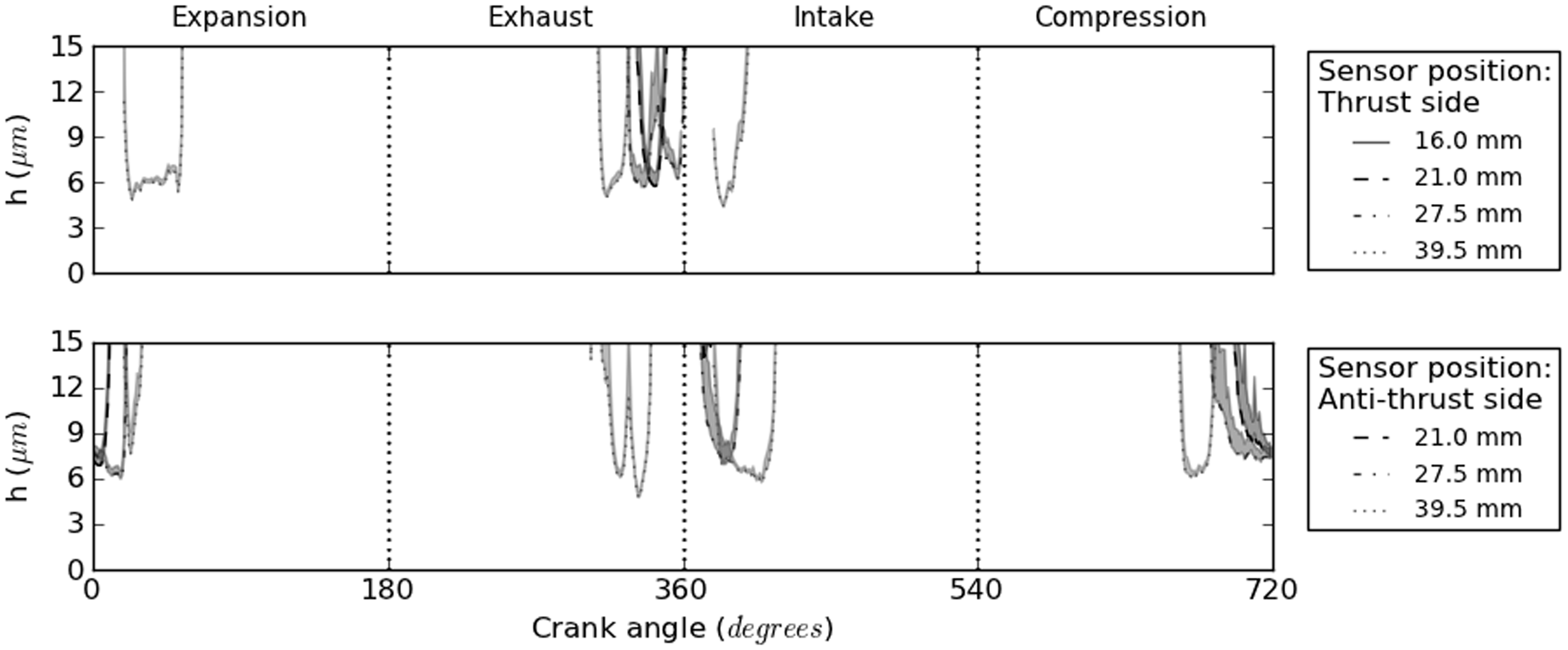
To aid analysis, the film thickness data for the four different test conditions have been plotted relative to the local skirt position. Each stroke has been segregated and plotted (on both the thrust and anti-thrust surfaces) to allow relative variations across the different tests to be observed. It should be noted that the film thickness measurements at different locations on the skirt do not correspond to a fixed crank angle in the cycle, i.e. it is not a ‘snap shot’ of the film. In order to improve clarity, the mean film only has been plotted and at skirt locations observed by multiple sensors, the minimum measured value has been considered.
Compression stroke
Figure 5 shows the film thickness over the two piston skirts during the compression stroke. As highlighted in Figure 3, the piston is operating with a clearance during motored running, with a film only observed over the anti-thrust surface and having a minimum value of around 6 µm. Given that the nominal clearance for the piston in this engine is 150 µm when cold, if the piston sits in a relatively ‘flat’ orientation, the result presented would be expected, given that for the particular ultrasonic conditions of this test, the limit of film measurement is around 15 µm. It should be noted that a ‘lack’ of film could also occur in the case of a two phase film, where air or vaporised oil is present (as would occur if starved or cavitating). Such a condition would cause a large reduction in the stiffness of the film and cause it to behave as though a thicker film were present. However, given the low loading conditions and the presence of a film during fired tests, it is most likely due to the clearance only.
Skirt films measured during compression stroke at 4000 r/min.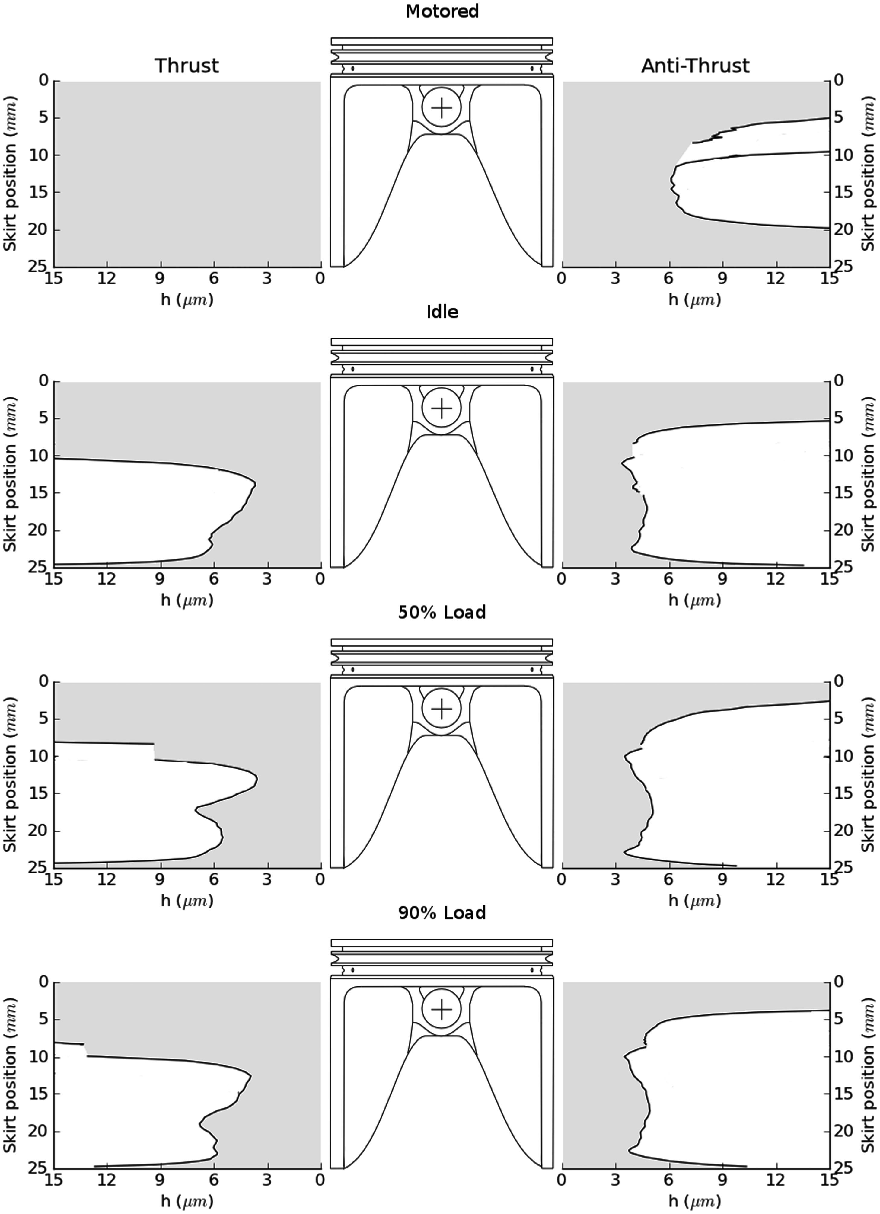
For all fired cases, a ‘thin’ film is observed on both skirt surfaces; however, this extends approximately 5 mm higher on the anti-thrust surface. This asymmetry may result from a slight canting of the piston given the pressure loading over the crown.
For each of the fired cases, the minimum film on both thrust and anti-thrust skirt surfaces are nominally similar (between 3.5 µm and 4 µm); however, a ‘double minimum’ is observed on the anti-thrust surface for each fired condition, positioned at approximately 10 µm and 23 µm from the top of the skirt. If again the exhaust stroke is considered, a similar response is observed; however, for the intake stroke the film is virtually constant at 4 µm. It is suggested that the film profile during the compression stroke is the result of a small rotation of the piston as it translates upwards along the bore, depicted in Figure 6.
Possible (exaggerated) piston motion giving rise to double minimum observed during compression and exhaust strokes.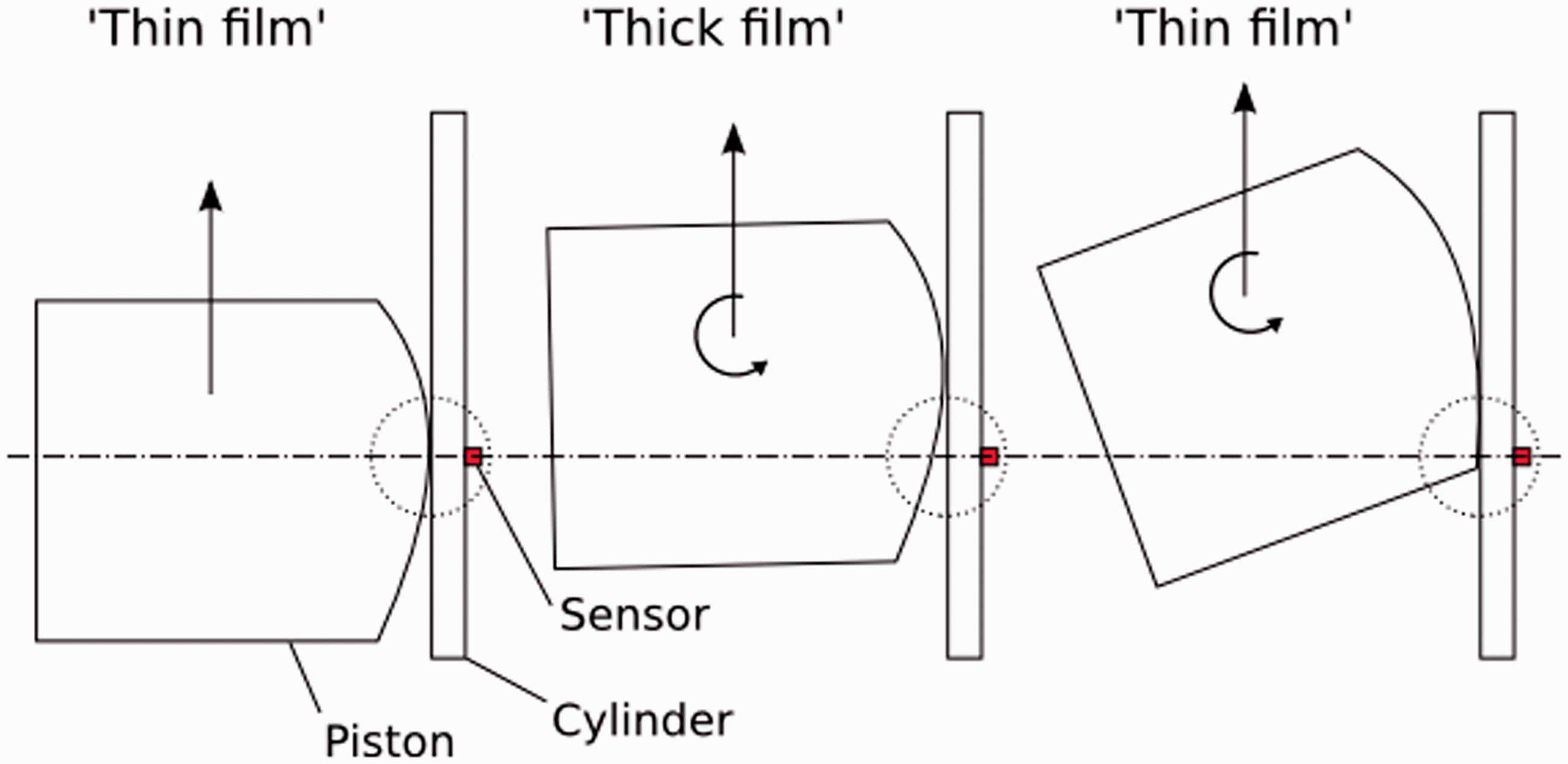
Expansion stroke
Figure 7 depicts the film measurements for the expansion stroke, which shows the greatest sensitivity to engine load conditions. As with the compression stroke (but in the opposing sense of skirt surfaces), the clearance and skirt compliance causes the dominance of a thin film on the thrust side of the piston; however, the piston remains in contact with the anti-thrust surface for a short period after TDC, where it appears to undergo a translational motion across the cylinder. This is characteristic of ‘piston slap’ where the clearance coupled with combustion pressure cause the relatively energetic translation of the piston across the bore and generally occurs at warm-up or as a result of poorly matched/worn components. To aid visualisation, Figure 8 shows the relative occurrence of the measured films with respect to crank angle for both the motored and fired conditions.
Skirt films measured during expansion stroke at 4000 r/min. Piston slap as a result of clearance during motoring at 4000 r/min.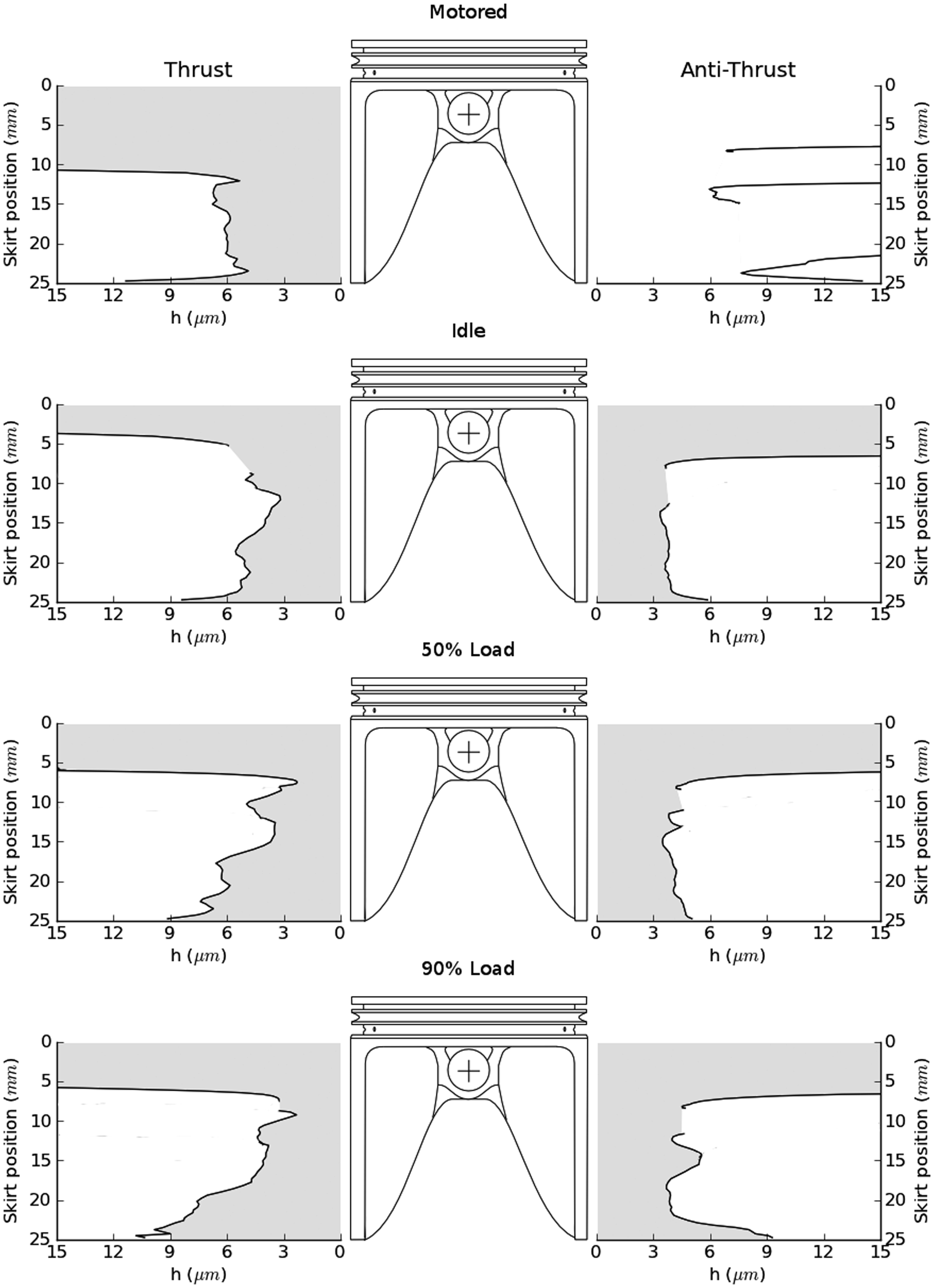
Considering skirt and cylinder stiffness
For this experimental set up, measurement positions were limited by accessibility, enabling only axially aligned sensors to be mounted. However, the local compliance of the skirt varies considerably over its area, being supported most rigidly at the crown and lateral webs. Though the variable axial compliance can be observed in the results presented here, further experimental work is required to highlight the effect of global skirt compliance on film thickness. For the most part, liner stiffness has also been neglected and been assumed to be perfectly round. It is probable that the machining operations carried out on the water jacket under cold, un-loaded conditions will have resulted in stress relieving deformations, potentially introducing local piston-liner clearances. Such a situation may go some way to explaining the fluctuations observed in Figure 8. Future work using a separate, thick walled wet-liner arrangement will improve bore roundness and correspondingly, the structure of the film.
Influence of piston roughness
The plotted film thickness results refer to the measured oil layer thickness that exists between the piston and the cylinder. For this paper, the term ‘minimum film’ has been defined as the minimum measured using the described ultrasonic method. It should be clarified, however, that pistons generally have an intentional roughness imparted by the machining process. Such roughness enables pockets of oil to be trapped, aiding oil availability along the length of the skirt. Arguably, the term ‘minimum film’ could be related that which separates the skirt and cylinder at the peaks of the machining marks found on the skirt.
To put this into context with the presented plots, the piston used exhibited a plateau flattened ‘saw-tooth’ roughness profile having a peak-to-peak height of ≈10 µm and pitch of 0.3 mm. To the transducer, the oil trapped in the roughness will behave as an additional layer of lubricant; the height of the roughness being much smaller than the wavelength of the ultrasonic pulse. If the equivalent thickness of oil is considered (based on the relative area of oil trapped in the roughness when compared to the peak-to-peak extent), an equivalent ‘trapped oil’ film thickness of ≈3.2 µm is obtained. The plotted results refer to the mean (measured) film thickness present at the piston skirt interface (i.e. including the trapped oil). Defining minimum film thickness as being the separation between the peaks of the roughness and the cylinder wall, it can be seen that by subtracting the ‘trapped oil thickness’, a nominally zero minimum film thickness is obtained (matching the typical polishing patterns observed on piston skirts). If this minimum film is termed the ‘true minimum films thickness’, it is worth noting that sub-zero films would be suggested by some of the results of Figure 7. Clearly such values are not plausible and the reason is likely to come from increased skirt wear in these regions, reducing the true ‘trapped oil’ film thickness.
Piston motion considerations
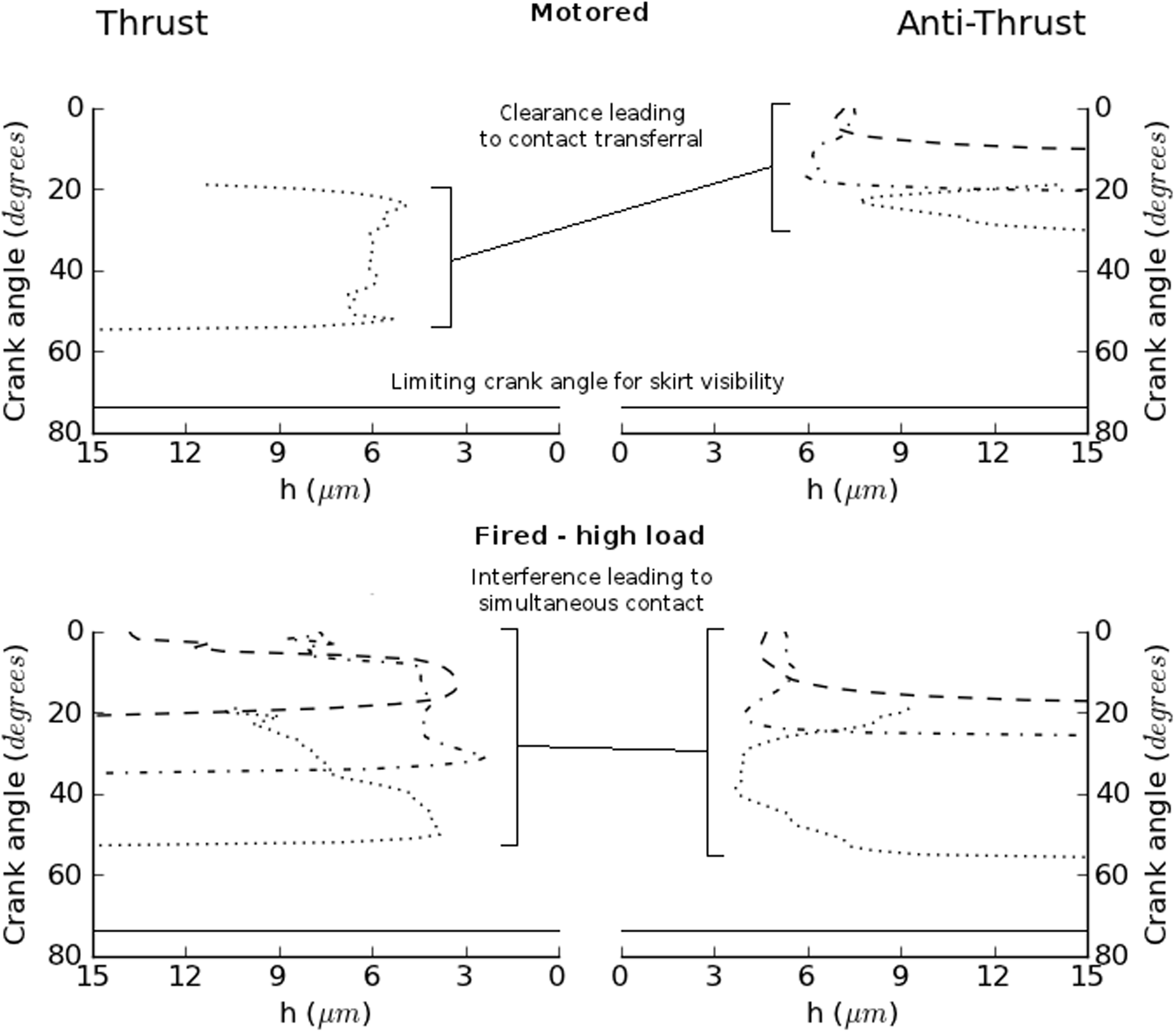
Obtaining measurements at multiple locations provides a possible route to infer some of the secondary motions of the piston by considering both the skirt positional and crank angle measurements. In the motored case (Figure 8), the piston initially sits against the anti-thrust surface before disengaging, translating over to the thrust surface and continuing downwards, highlighting a clearance exists between piston and cylinder. During the fired conditions, however, the piston is simultaneously engaged on both thrust and anti-thrust surfaces suggesting it is running in interference. Figure 9 combines the crank angle and skirt positional film information to give an indication of the piston secondary motions occurring.
Piston secondary motions inferred from film thickness measurements.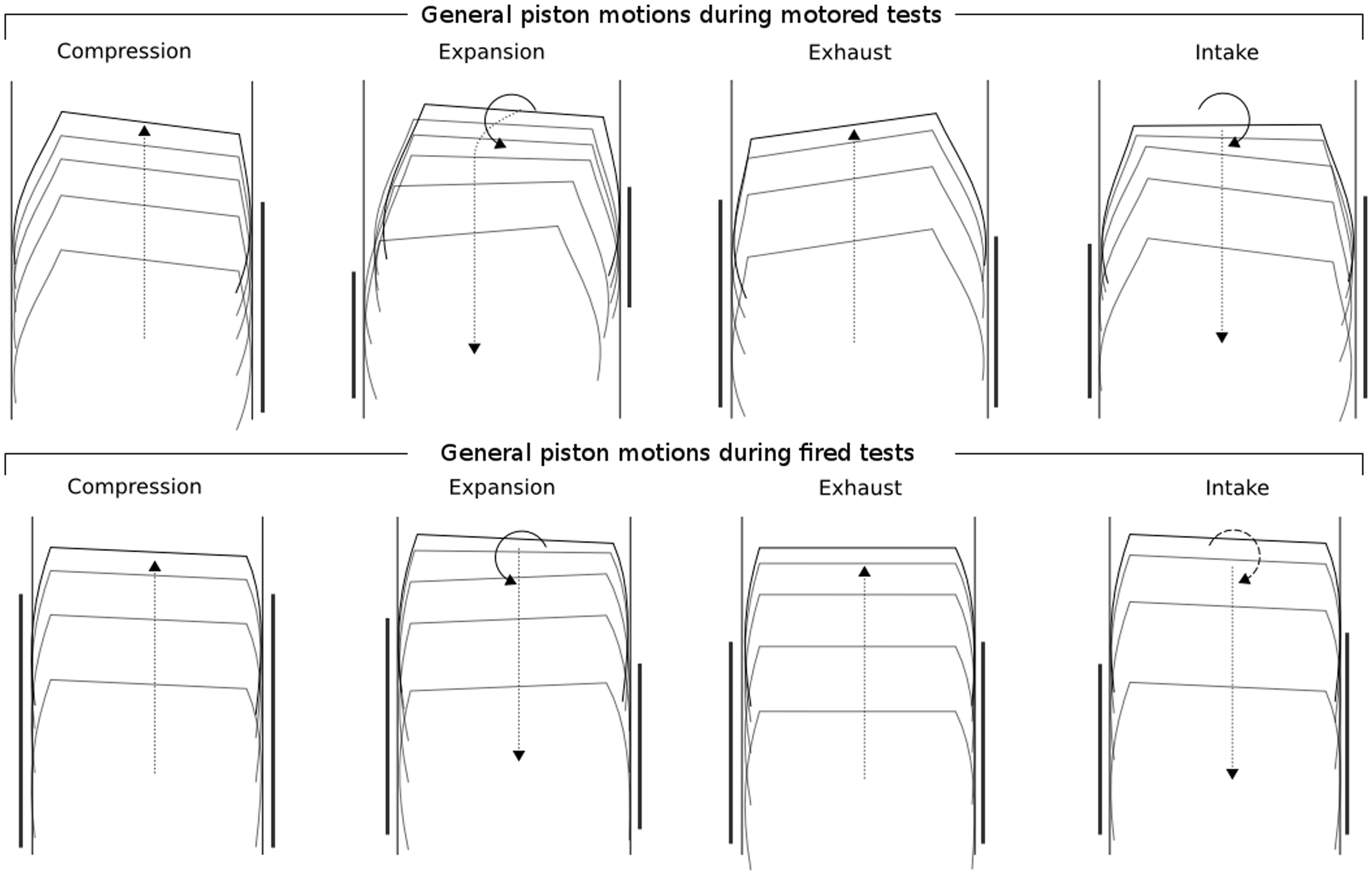
During the motored tests, the compression stroke sees the anti-thrust surface translate in close proximity to the cylinder with clearance on the thrust side. During expansion, the piston translates across the cylinder, before continuing downwards. During fired tests the ‘hot’ condition of the piston means that the secondary motions become much less pronounced, with little or no piston clearance. During the compression stroke, anti-thrust contact dominates, with thrust contact existing over the lower portion of the skirt. However, the thrust surface contact dominates the expansion stroke, with the lower portion of the anti-thrust surface contacting the cylinder wall. Both exhaust and intake are relatively similar suggesting the piston runs in a relatively symmetrical orientation.
Comparisons with work by other authors
The skirt, when compared to the ring-pack, has seen relatively sparse experimental effort to obtain film measurements. In the results that are published, similarities in magnitudes and deductions of spatial film distributions are observed. Results from a motored diesel engine 1 using full-field LIF showed that sub-8 µm were being generated over a significant portion of the anti-thrust surface during compression as a result of the thrust loading. Experimental work carried out on a motored gasoline engine in Ohsawa et al. 12 suggested minimum films of between ≈2 µm and 40 µm were being measured, though a possible error of around 10 µm was stated with measurements. Films as low as 1 µm were measured on the anti-thrust surface of a diesel engine during the compression stroke at 2000 r/min and 25% load, again using LIF. 2 The study of Taylor and Evans 3 involved measurements using inductive transducers mounted within the skirt of the piston. The engine was run fired at 1000 r/min and approximately 40% load. Though these measurements were of skirt clearance (the presence of the lubricant is not integral to the measurement process as it is with LIF and ultrasonic techniques), lubricant films would have almost certainly existed at the sub-10 µm proximities measured. As with the work presented in this paper, the thinnest films were observed towards the upper, stiffer portion of the skirt.
Conclusions
A series of tests have been carried out to ultrasonically measure lubricant film thickness over the thrust and anti-thrust surfaces of a piston operating in both motored and fired conditions. A four-stroke single cylinder engine operating at 4000 r/min was used and instrumented with piezoelectric elements mounted on the exterior surface of the cylinder. These elements were used to both pulse and capture ultrasonic signals, highlighting the non-invasive nature of the technique. Films measured during motored conditions showed the existence of clearance between the skirts and cylinder wall, while the low side loading and higher oil viscosity promoted thicker film formation. Fired tests have shown the piston operating in an interference condition with simultaneous thin film measurements on both thrust and anti-thrust surfaces. During the expansion strokes, the minimum film has been shown to reduce with increasing load with the thinnest film of the highly loaded tests (≈2.5 µm) positioned approximately 1/3 of the way down the skirt surface, an expected observation given the axial stiffness profile of the skirt. The resulting film profiles have been used to build a picture of piston secondary motion, suggesting piston-wall disengagement during motored conditions and loading distribution during fired conditions.
Footnotes
Acknowledgements
The authors would like to express their gratitude to the funding agency and to the academic and industrial partners in the consortium for help and support.
Conflict of interest
None declared.
Funding
The work carried out in this paper has been financed in part by the Encyclopaedic consortium set up by the EPSRC.