
Abstract
In this work, a protective structure with 2A12T4 aluminum alloy as the panel material and plywood as the core layer was designed. Penetration experiments were performed by firing multiple projectiles from a light gas gun. The impact behavior, damage mode, absorbed energy, and residual strength of the interlayer after impact were studied. The dynamic response and the failure of the interlayer were analyzed. Disbonding, fiber fracture, buckling, shear, and core fracture between the metal layer and the composite layer of the front panel were observed. The impact resistance of the sandwich plate was also studied. Based on the results of the experiments and numerical simulations, failure determination of the plywood core layer was achieved using the Hashin criterion, and a finite element model was established using ABAQUS software. High-speed impact testing was performed with a Hopkinson pressure bar. The stress–strain relationship under a high dynamic strain rate is given here, and the energy absorption efficiency under loading in different directions was analyzed. Finite element analysis of the representative volume elements in the wood microstructure was also carried out. The results reported here can be used to guide optimal design of sandwich structures suitable for use under high-speed impact conditions.
Keywords
Introduction
As a result of the deterioration of the environment and shortages of natural resources, many recyclable environmental materials are being used increasingly commonly. Wood, which is a naturally-grown high-performance material, has been used widely in a range of applications. Because of this wide application range and its low cost, researchers are viewing wood with growing importance as the core material for sandwich fiber-reinforced polymer (FRP) composites. The mechanical behavior of sandwich structures is dependent on the geometry and the material properties of both the core materials and their faces. 1 Because of their high stiffness/strength-to-weight ratios and their stability under both buckling and torsional loads, traditional sandwich structures have symmetry in both their materials and their geometries. The core and panel panels in a symmetrical sandwich structure may have different thicknesses and materials, and any combination of these materials can be used. The different combinations have different material properties and will provide numerous options for the design of sandwich structures.2,3 Typically, sandwich structures consist of a high-stiffness outer plate layer and a low-elastic-modulus core layer; these structures are designed to save weight while also maximizing protection by combining metals with composite materials.
Qi et al. 4 and Shi et al. 5 conducted experimental and analytical research on the bending stiffnesses of glass-fiber reinforced plastic (GFRP) beams with wood-core sandwich structures. They concluded that the numbers of lattice networks and their orientations controlled the pseudoductility of the beams. Keller et al. 6 developed experimental approaches to investigate the mechanical responses and the failure modes of GFRP-balsa sandwich decks. Zhou et al. 7 described the effects of temperature on the structural bond integrity of wood when bonded with aramid, basalt, and carbon fiber-reinforced polymer (CFRP). Ferdous et al. 1 studied the bending responses of GFRP sandwich beams with different core coatings and concluded that the coatings could prevent wrinkling and buckling failure of the panels. Labans et al. 8 evaluated the bending responses of sandwich panels composed of cellular wood/plywood stiffeners and thermoplastic composite cores. Susainathan et al.9,10 studied the impact and compression after impact behavior and the failure modes of sandwich panels composed of plywood cores and fiber-reinforced composite skins. Fatima et al. 11 evaluated the maximum load, the energy dissipation capacity after impact, and the failure modes of CFRP/wood-sawn laminated composites. It can be concluded from the results in the papers discussed in this short literature review that the energy absorption capacity of wood-core composites is much higher than that of composites without these wood cores.
In addition, studies of a variety of structural combinations, including honeycomb sandwich structures,12,13 honeycomb sandwich cores with tubular structures, 14 and composite truss core sandwiches, 15 showed that impacts produce a densification effect in the fluffy compressible core layers. To some extent, an X structure provides better performance in terms of resisting impact damage and absorbing the impact energy. The mechanical behavior of the core layer materials is an important factor and serves as a basis for the study of sandwich structures. There are multiple possible failure modes of anisotropic materials, e.g., matrix cracking, delamination, and fiber fracture, and there are complex interactions between the fibers and substrates, including in the X structure. When the damage at the impact point is concealed within the middle layer, cracks that lead to local failures are generated, and these failure areas reduce both structural strength and stiffness.16,17 By studying the interactions between the various failure modes under high-velocity impact, the initiation and propagation of the damage can then be understood.18,19,20
Forrestal et al. 21 studied positive and oblique impacts on aluminum plates and then drew the ultimate velocity curve for the projectile body. Iqbal et al., 22 Ansari et al., 23 and Gupta and Madhu 24 conducted relevant impact experiments on metal targets composed of single materials. Initially, they analyzed the influence of individual metals on the damage results obtained under different conditions. Falzon and Apruzzese 25 proposed damage evolution models that corresponded to different compound failure modes. Kistler and Waas 26 conducted experiments and performed analyses of the responses of curved laminated composite plates to low-speed impacts. Fleck et al. 27 proposed a typical three-phase analytical model of the behavior of clamped sandwich beams under impact loads, which laid a foundation for relevant theoretical research. When combined with extensive experimental and numerical simulation studies, analytical models can predict the dynamic responses of sandwich structures. Atas and Sevim 28 studied the impact behavior and the failure modes of polyvinyl chloride (PVC) foam/balsa wood core sandwich composites. Reddy et al. 29 developed a quasistatic and low-speed impact test to assess the deformation and impact energy absorption behavior of cell-type sandwich structures. Walsh et al. 30 studied the ability of cork–carbon fiber sandwich composites to absorb dynamic impact energy. All these studies aimed to explore the forms of both damage and failure of protective structures under application of impact loads. Therefore, it is very important to explore the compression behavior of the core layers under various impacts to understand the protection provided by these lightweight protective structures from impact loads.
Although many researchers have studied the mechanical properties and the quasi-static failure mechanisms of wood and wood-like materials, the compressive deformation properties of wood when subjected to high-speed impacts have rarely been mentioned in the literature. To enable the study and design of composite structures, impact damage tests were conducted in this work to study matrix cracking, fiber/matrix debundling, delamination, and fiber fracture. 31 In this paper, a numerical simulation model for two types of projectile striking a metal-wood target plate is established and a numerical simulation study of the impact protection of the target plate from a No. 45 steel projectile body is performed. Based on the experimental results and numerical simulations, the effect of the bullet head shape on its penetration and protection performance is analyzed. As an orthotropic material, wood exhibits different physical properties in its axial and transverse loading directions. In this study, a light gas gun and a Hopkinson pressure bar are used to perform high-speed impact tests. The stress–strain relationship under application of a high dynamic strain rate is given and the energy absorption efficiency is analyzed under different loading directions. The anisotropic behavior of wood under axial and transverse compression conditions is simulated via finite element (FE) analysis of the representative volume elements in the wood microstructure.
After the numerical model is verified using the experimental data, the energy absorption mechanism related to the deformation and failure of the aluminum plate can then be analyzed further. In addition, both experimental and numerical techniques can be used to study the effects of the impact velocity, the target thickness, and the warhead shape on the failure mechanism. The results provide a new means and method to study the energy absorption and the failure mechanism behind the perforation process, and can provide a better understanding of the structure’s mechanical response to different impact conditions. The results presented in this paper provide new and relevant information for the design of structures that are likely to be affected by impact loads.
Problem statement
A bullet struck a target plate that consisted of a square sandwich structure composed of aluminum alloy and wood with a side length L, as shown in Figure 1. In the figure, the aluminum alloy panel thickness is b, and the thickness of the wood layer is H. The panel material is an isotropic metal, and the plywood core layer is wood that was orthogonally laid and bonded, and is thus modeled as an anisotropic material. The tensile traction model is used for the bonding layer. A bullet with diameter D, mass M, and initial velocity V strikes the center of the target plate. It is assumed that the bullet is rigid when compared with the sandwich structure, and that the circular arc S/D=3 (where S is the bullet head arc radius) at the tip of the bullet is a 3CRH-type oval shape.
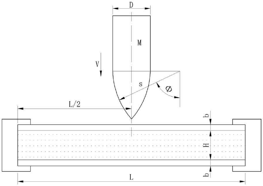
Schematic diagram of a bullet that strikes an aluminum alloy-wood sandwich structure.
Under high-velocity impact, the stress wave diffuses within the target plate toward the edge regions. At this time, the total deformation of the panel can be divided into local indentation and overall depression.32,33 For sandwich structures that contain a relatively weak core layer, the process of the bullet penetrating the target plate under high-velocity impact can be divided into the following three stages:
In the first stage, the bullet hits the target plate, the upper plate surface is damaged, and the target plate is deformed.
In the second stage, the core layer beneath the bullet undergoes local fragmentation and shearing. As a result, the crushed core layer forms a plug, and the bullet and the plug move at the same speed.
In the third stage, when the core layer below the bullet is fully compacted and broken, the stress is then transferred to the rear backplane. Because of the change in boundary conditions, the damage area may be different to that on the incident surface. Finally, the back plate breaks, and the sandwich structure is penetrated completely.
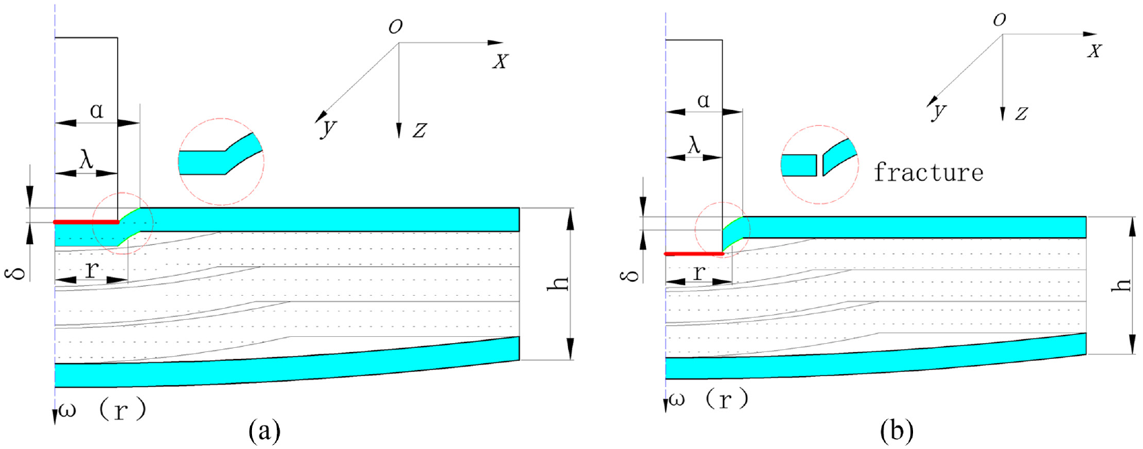
R3 Bullet Impact
Under the high-velocity impact of a bullet, most of the kinetic energy is absorbed by a sandwich plate through structural deformation, and the remainder is in the form of the residual kinetic energy of the bullet.34,13 In this study, the target plate was clamped. When compared with the local indentation caused by interlayer extrusion, the overall elastic deflection of the panel underwent relatively little change under the high-velocity impact. Therefore, the strain energy caused by elastic deflection of the panel could be ignored, and the potential energy

where
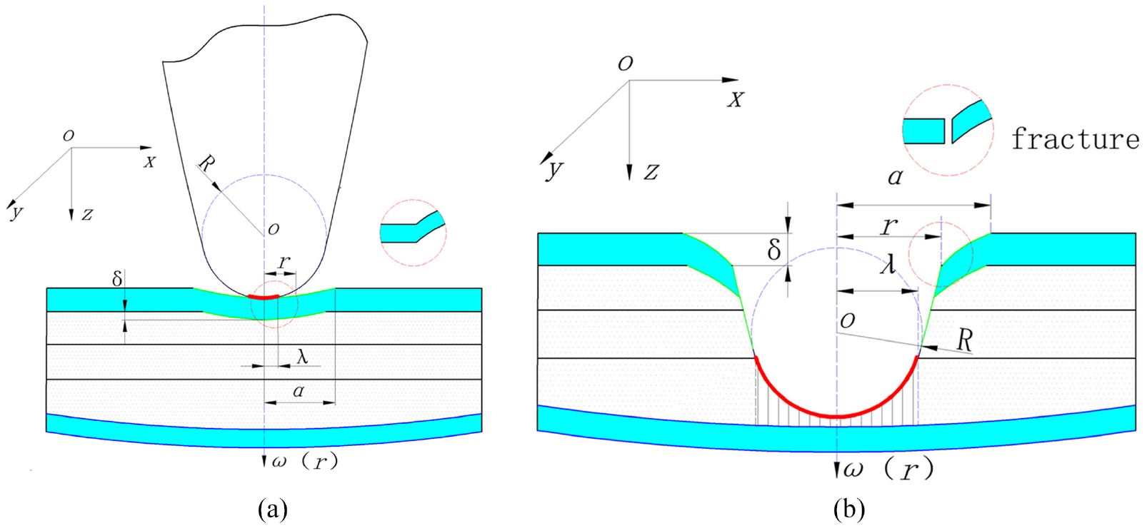
R3 bullet impact diagram. (a) Panel elastic-plastic damage and (b) panel breakdown diagrams.
On the impact of an R3 bullet, the cross-sectional area

where R is the radius of the arc of the warhead,
In this experimental study, all samples went through the deformation mode, as shown in Figure 2. Because of the small bending stiffness of the thin surface, the bending strain energy could be neglected in this case. The membrane strain energy of the panel

where

The potential energy of interlayer deformation was mainly caused by breaking and shearing. The strain distribution had little effect on the energy of the interlayer. Therefore, it was assumed that the compressive strains in the interlayer were distributed uniformly. The deformation profile of the impact extrusion part of the sandwich structure could be divided to form the same shape as the warhead. The compressive strain of the laminated plywood

where

where

where

where

The residual kinetic energy
By using equations (1), (5), (7), (9), (10), and (11), the contact force P can now be expressed as:

A sandwich panel that is subjected to a high-velocity impact undergoes local deformation, which is dependent on the local indentation of the front (top) panel to a considerable extent. The experimental results showed that the significant reduction in the contact load was caused by the crack in the front (upper) surface. Therefore, the initial peak load can be characterized by using the onset of the fracture failure in the front panel. 38 To capture the onset of the panel cracks, the maximum shear strain criterion was used to determine the initial peak load here:


The critical peak load
Flat Head Bullet Impact
When the core layer was densified by the impact, a columnar shear plane formed, and a truncated conical crack then formed; i.e., punching occurred, as shown in Figure 3.
Flat head bullet impact diagram. (a) Panel elastic-plastic damage. (b) Panel breakdown diagram.
The cross-sectional area

Similar to the derivation for the impact of the R3 bullet, the membrane tensile energy of the top panel
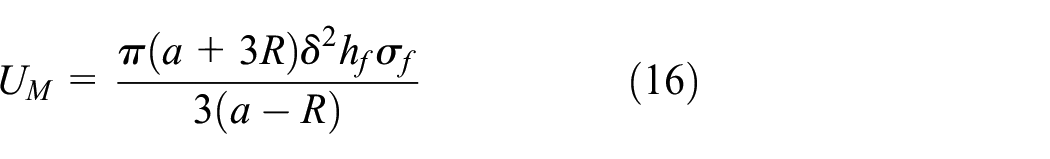
The compressive energy

Therefore, the impact load can be determined using:

To determine the conditions required for failure to occur when the bullet hits the lower panel, the maximum principal strain criterion was used to determine the initial peak load as follows:
where

Experimental study of high-velocity impact
To explore the protection that can be provided by a sandwich structure, two structures were fabricated and compared. The impact comparison experiment was conducted using flat head and R3 oval projectiles. The experimental data were obtained and the trajectory for the limiting velocity was drawn.
Preparation of Composite Materials
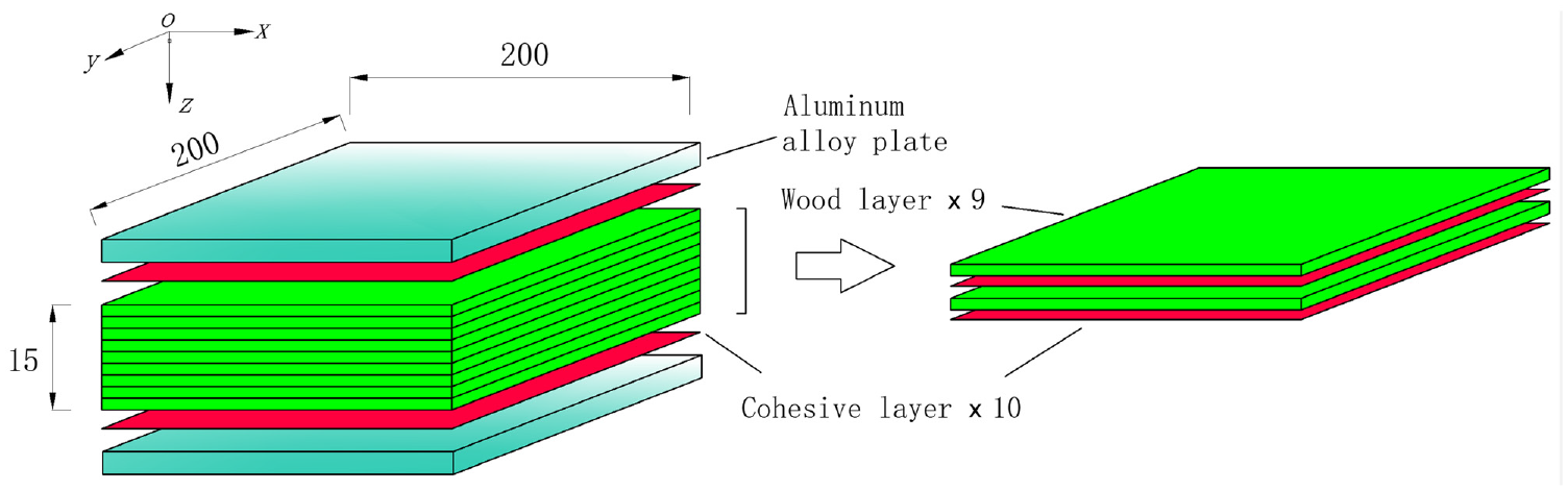
In the experiment, multilayer poplar plywood with a density of 0.4 g/cm3 was used as the core layer of the target plate. To characterize the mechanical properties of plywood when laminated with an anisotropic material, quasi-static experiments were conducted to obtain the parameters required. The panel material for the target plate was the isotropic aluminum alloy Al2A12-T4. 39 The target plate was composed of three layers, comprising a metal layer, a wood core layer, and a cohesive layer. The target plate dimensions were 200 mm×200 mm.
The target plate core layer was prepared using nine layers of spinal-cut poplar pieces that were laid orthogonally [0°/90°/0°] and then bonded to prepare plywood with a thickness of 15 mm. To explore the impact damage mechanism, the sample preparation process was divided into two process types for comparison, and two overlapping modes were designed: (1) a two-layer structure, with the 2A12 aluminum alloy acting as a panel to withstand the impact of a bullet and plywood acting as a backplane placed in the lower layer, as shown in Figure 4; (2) a three-layer structure, with the 2A12 aluminum alloy placed at the front and on the back of the sample to act as the panel and the backplane, respectively, with plywood acting as the core layer to form the three-layer structure, as shown in Figure 5. The target plate was cut uniformly using a computer numerical control chainsaw with a tolerance of ±0.2 mm. The impact area was a circle with a center diameter of 140 mm. Use of different stacking sequences resulted in fabrication of laminates with different interlayer interfaces. After preforming, the samples were baked in a drying oven at a constant temperature for 8 hours. The moisture content of the treated plywood was estimated to be 8%. The production process for a three-layer sample is shown in Figure 6.

Schematic diagram of the two-layer sample.
Schematic diagram of the three-layer sample.

Preparation of the three-layer impact samples.
The basic parameters of the three-layer target composite are listed in Table 1.
Basic parameters of the composite materials (wood and aluminum alloy).
High-Velocity Impact Experiment
The high-velocity impact experiment system was composed of a high-pressure air pump, a gun barrel, a bullet, an impact protection chamber, a high-velocity camera velocity measurement system, and other components. The launching tube diameter was 12.7 mm, and the mass of the bullet was 34 g, as shown in Figure 7. The complete experimental process was recorded and measured using the high-velocity camera system. The target plate was placed on a support frame with the edge bolted to the frame and it was then struck with a 7.62-mm-diameter steel bullet. To study the dynamic behavior and damage mechanism of the plate and obtain the velocity gradient data required, we conducted several experiments.

High-velocity impact experiment equipment.
At the beginning of each experiment, a bullet was loaded into the air gun through its loading port and sealed inside a cylindrical shell. The gas storage chamber was operated using a valve control system. The pressure in the gas storage tank was provided by a pressure source (a cylinder), and the release time and the loading speed of the bullet were controlled via the valve control system. After the valve was opened, the metal projectile was accelerated along the hole under high gas pressure until it left the hole and struck the target plate. During the loading process, the target plate deformation process was photographed using a high-velocity camera located at the plate’s side. The camera shooting time included a 0.5 s delay.
The bullet was designed to have either a flat head or an oval head with a uniform diameter of 12.7 mm. By controlling the length and the concave groove of the tail, the center and the mass were adjusted to give a uniform mass of 34 g. The sizes of the bullets are shown in Figure 8.

Schematic diagrams and photograph of the two bullets.
Experimental Results
The bullet strikes the target plate, with resulting damage and fragmentation. The details of the experimental data are listed in Tables 2, 3, 4, and 5. The samples were numbered as follows: A1: two-layer target, R3 bullet impact; A2: two-layer target plate, flat head bullet impact; A3: three-layer target plate, R3 bullet impact; and A4: three-layer target plate, flat head bullet impact. The energy absorbed by the bullet upon impact

where
Experiment A1: R3 bullet striking a two-layer panel.

Experiment A2: Flat head bullet striking a double-layer panel.

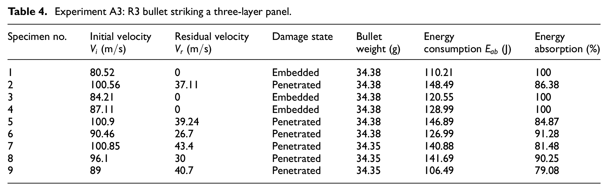
Experiment A3: R3 bullet striking a three-layer panel.
Experiment A4: Flat head bullet striking a three-layer panel.

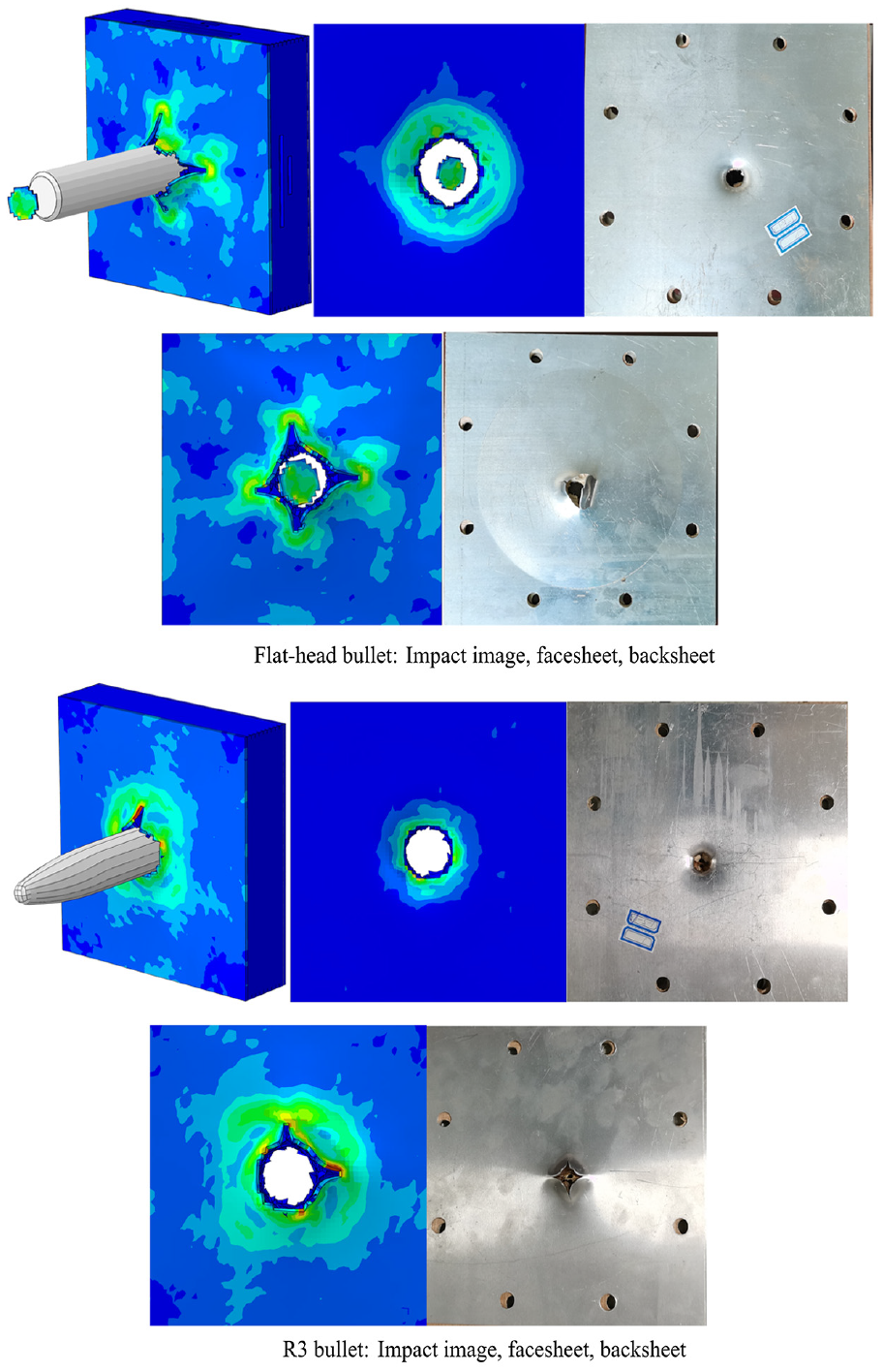
Four types of tests were performed on the two-layer and three-layer target plate samples using both R3 and flat head shells, and the impact velocity and flight residual velocity data were obtained from the frame numbers and the images. The impact images are shown in Figure 9.

Experimental images of the high-velocity impacts.
In penetration of the ductile aluminum alloy, kinetic energy consumption was mainly used to balance the internal work dissipation. When cylindrical cavities were used to approximate the ductile reaming effects, the sandwich plate structure was idealized as being formed of multiple independent thin layers oriented perpendicular to the direction of penetration. The equation for the surface was proposed by Lambert and Jonas for

where

Curve fitting of the ballistic limit was conducted according to the experimental data and equation (23), with results as shown in Figure 10. Finally, based on an energy analysis of the table data and the images, the ballistic limit of the R3 bullet in experiment A1 was 80 m/s and the average breakdown required 108 J. The ballistic limit in experiment A2 was 73 m/s and the average breakdown required 91 J. In experiment A3, the ballistic limit was 87 m/s and the average breakdown required energy of 128 J. The experiment A4 ballistic limit was 106 m/s and the average breakdown required 190 J.

Experimental data: (a) two-layer target plate; and (b) three-layer target plate.
It was concluded that the impact damage could be classified as either tensile failure or shear failure. The shear failure and the shear damage formed earlier than the tensile cracks, and the proportion of the shear failure increased gradually with increasing speed. When the two types of crack were superimposed, the sandwich structure was penetrated, and the impact caused either tearing or plugging failure.
Numerical simulations
The FE model was established using ABAQUS/Explicit software (Dassault Systèmes). According to the experimental conditions, a numerical model was established to draw two types of bullet: the ovoid R3 and the flat head round. The bullet hits the target plate at velocities of 70 to 130 m/s. The modeling procedure is illustrated in Figure 11. This section contains descriptions of the numerical FE models, the material parameters, and the constants of selected plastic models used in the simulations. The interaction between the rigid projectile, the composite surface, and the core is determined by using the eroded surface-to-surface contact interface. An automatic single surface contact algorithm is defined for each part using the self-selection method. The core-layer damage constitutive criteria and Hashin damage evolution criteria were written into VUMAT subroutines in Fortran and then implanted into the ABAQUS/Explicit FE model to simulate and analyze the impact process of the target plate. The size and layout of the model are consistent with the experimental parameters.

FE model of a sandwich structure undergoing a high-velocity impact.
Finite Element Model
Geometry
The wood fiber and high-strength aluminum alloy plates were modeled using deformable solid elements in 21 layers. To reveal the damage to the affected region effectively, the local mesh encryption method was used. The element size was 0.25 mm. Analysis of the convergence of the FE model of the aluminum alloy plate and the plywood core layer allowed the mesh size to be determined. The mesh sensitivity study showed that the element size of 0.25 mm could balance the simulation accuracy well with the simulation efficiency, and the friction coefficient between adjacent elements was 0.25.
Boundary conditions
Fully built-in (U1 = U2 = U3 = UR1 = UR2 = UR3 = 0).
A convergence study was conducted to determine the minimum element size required.
Meshing
The metal model of the aluminum plate in the FE analysis was based on a J-C model hexahedral mesh, which was a deformable three-dimensional solid. The mechanical connection was fixed by attaching bolts between the aluminum plate and the wood layer, and a cohesive force unit was also added between the core layer and the wood. When compared with the target plate, there were no obvious changes in the bullets before and after the experiments. The grid properties of the impacted target plate components are shown in Table 7.
Finite element meshing of the laminates.

The mesh size has a major influence on both calculation accuracy and calculation efficiency. Therefore, mesh sensitivity analysis was performed for the sandwich structures. Figure 12 shows the effects of the mesh size on the simulation results and the solution time required for analysis of the impact of an R3 bullet at 100 m/s.

Mesh sensitivity analysis.
Anisotropic Damage Criteria
Assuming that the top and bottom panels conformed to the rigid-complete plasticity law for their yield strengths, the poplar boards were modeled as anisotropic nonmetallic materials using single-layer wood models and damage criteria.
Hashin damage criterion:
(1) Fiber failure


(2) Matrix failure


where the subscripts 1, 2 and 3 represent coordinate directions; i.e., 1 represents the fiber direction, 2 represents the direction perpendicular to the fiber direction in the laminate surface, and 3 represents the thickness direction for the laminate overlay.
Initial parameters of aspen wood (wood and composite plies).

Mechanical Parameters of Materials
Wood core layer material model
The core layer was made from poplar plywood composed of 5-mm-thick and 15-mm-thick orthogonal layers, and a tensile sample was fabricated. A 100-kN multifunctional electronic tension machine was used to perform quasistatic testing at a tensile rate of 10 mm/minute. Tensile, compressive, and three-point bending experiments were performed to obtain the static parameters of the material. When compared with the wood alone, the plywood structures showed better physical properties because the plywood material offered better mechanical behavior. Stretched samples are shown in Figure 13.

Stretched plywood samples and stress-strain curves.
Model of aluminum alloy
An impact wave is generated during the high-velocity impact process and the equation of state of an impact wave was thus selected in this study. The target and the projectile in the impact experiment are both metal materials; therefore, the equation is a linear impact equation of state. The material parameters are given in Table 9. The linear impact equation of state is:

where
Equation of state parameters for the 2A12 and 45 steels.

Because the surface damage of the 2A12 steel was mainly plastic deformation and failure, 2A12 was adjusted in the manner of the study of Hou et al., 41 and the J-C model was used to define the failure model42,43 as follows. The equivalent fracture strain was:


where
The parameters of the aluminum alloy are presented in Table 10.
2A12-T4 alloy parameters (aluminum skin).
Parameters of the surface cohesive tensile traction model
Multilayer plywood structures use orthogonal layers of wood, and models of these layered structures include models of the stretch-traction between the wood layers. The parameters of the cohesive element used to bond these surfaces are given in Table 11.
Material parameters of cohesive element. 44

The Benzeggagh–Kenane fracture criterion 45 was implemented, as shown in equations (30) and (31).

where
Split Hopkinson pressure bar test
Starting with the experimental method, the dynamic compression behavior of plywood was tested. To study the dynamic mechanical behavior of the plywood core layers and provide data to form a basis for the establishment of an FE model, and based on the assumptions of a one-dimensional stress wave and uniformity, 7075 aluminum alloy was used as the impact rod for the first stage air cannon in the high-velocity impact dynamic experiments. Sample fabrication and experimental equipment are shown in Figure 14.

Schematic diagram of the split Hopkinson pressure bar.
From plywood dynamic loading test sample production to the high-velocity impact tests used to obtain the material dynamic strain rates, during analysis and processing of waveforms and sensor data voltage amplitudes, and during acquisition of the incident waves


where

Hopkinson impact waveform and sample stress–strain curves.
Numerical results and discussion
Ballistic Limit Model Verification
The dynamic and static mechanical properties of the materials obtained from the experiments were input into the ABAQUS software to perform model calculations, and the results obtained were compared with the experimental data to verify the numerical experiments. A comparison of the results is shown in Figure 16.

FE model verification: (a) Experiments A1 and A2, and (b) Experiments A3 and A4 when compared with the model.
The residual velocities recorded under the different impact velocities were acquired by both experiments and FE simulations. Under the different impact conditions, the error between the numerical residual velocity and the experimental residual velocity was less than 10%. The numerical model’s predictions were thus accurate, and the numerical predictions were strongly correlated with the experimental results.
The main causes of the errors were manufacturing defects in the samples, measurement errors in the data, and differences between the FE simulation model and the actual experimental conditions. Figure 17(a) and (b) show comparisons of the sequential deformation modes at an impact velocity of 120 m/s. As shown in the figure, the initial-residual velocity curves and the deformation mode characteristics obtained from the experimental results and the simulation results were similar. From the FE simulation, the critical perforation velocity of the composite plate was 101.65 m/s, which was very similar to both the fitting results from equation (24) and the results of the experiment.

120 m/s R3 bullet striking the target plate: (a) Double Y-axis image of impact resistance–displacement–time characteristics, (b) double Y-axis image of impact velocity–drag acceleration–time characteristics, (c) critical image of the breakdown of the two-layer target plate, and (d) bullet partial flight image.
Plate Impact and Ballistic Impact Simulations
Figure 17(a) shows a double Y-axis image of the impact resistance-displacement–time characteristics from numerical simulation A3 at 120 m/s. Through the software analysis, when the time was 0.17 ms, the bullet penetrated the front and back of the target plate completely, and the displacement was then 17 mm. When the bullet continued to advance up to a time of 0.2 ms, the excessively circular part of the bullet tip penetrated the target plate completely, and the penetration resistance reached its peak. The numerical solution was 2858 N, and the displacement of the bullet was then 20 mm. The 20 mm secant divided the bullet penetration resistance curve into two areas. The bullet penetrated into the target plate but did not penetrate it completely. At this time, the target plate was squeezed by the projectile body and the panel was stretched and torn; this resulted in damage being caused by the accumulation of tiny strains.
The bullet contact state in Region I is shown in Figure 17(c). The mechanical response of the lower plate under the impact could also be divided into two stages. In the first stage, with increasing impact contact force of the bullet on the laminate, the displacement of the laminate increased rapidly, and the impact energy was transformed directly into the elastic specific energy of the laminate. At this time, the bullet penetrated the surface layer and damage to the core layer then began. In the second stage, the deformation of the laminates continued to increase uniformly, thus indicating that the impact energy that was absorbed by the laminates in the form of the deformation also increased steadily. The bullet continued to advance until the maximum contact force was reached. The R3 bullet penetration process in this area was a reaming process in which the target materials mainly produced radial displacement. At this time, the target materials were squeezed around along the curved section of the warhead, and the bullet holes then gradually expanded. The law of conservation of energy then determined the motion of the projectile body.
The critical state of the bullet in Region II, as shown in Figure 17(d), represented the friction force between the projectile body and the target plate when the bullet penetrated the target plate. At this time, during projectile body penetration stage 3, the contact force between the laminate and the projectile body dropped suddenly from the extreme value and then remained stable with slight fluctuations. This phenomenon indicated that the specimen demonstrated damage behavior after the load that the laminates could bear reached an extreme value, which led to a reduction in the stiffness of the laminates; therefore, the deformation continued to increase under the small stress. As the bullet holes increased in size, radial cracks began to form. The cracks were in a state of circumferential stress relaxation and gradually expanded to form petal-like openings.
Figure 17(b) shows the double Y-axis image of the impact velocity–drag acceleration–time characteristics at a 120 m/s impact. In zone I, the bullet penetrated the target plate gradually. At this time, the target plate was compressed to produce both deformation and damage, and these forces reacted on the projectile body to produce penetration resistance acceleration. In Region II, the curve of the projectile body’s breakdown of the target plate dropped rapidly toward the position at 0.4 ms, and subsequently dropped more slowly. At this time, the arc of the bullet tip passed through the target plate completely, and the radial friction of the cylindrical projectile body on the target plate produced drag acceleration.
Figure 18(a) shows the double Y-axis image of the impact resistance–displacement time characteristics from the numerical simulation of a flat head bullet experiment at 120 m/s. Because of the single cylindrical shape of the projectile body, the penetration process was divided into two stages. In the 0.24 ms time frame, the secant line divided the bullet penetration resistance curve into two areas. At this time, in area I, the stage 1 bullet was in the process of penetrating the surface layer without penetrating the backplane, and the bullet position was between that shown in Figure 18(c) and that in Figure 18(d). The bullet penetration resistance increased rapidly to a maximum until the two-layer structure was critically damaged; see Figure 18(d). In Region II, phase 2, the bullet’s velocity was reduced by axial friction.

Images of a 120 m/s flat head bullet striking the target plate: (a) Double Y-axis image of impact resistance–displacement–time characteristics, (b) double Y-axis image of impact velocity–drag acceleration–time characteristics, (c) critical image of breakdown of double layer target plate, and (d) image of bullet in partial flight.
Figure 18(b) shows the double Y-axis image of the impact velocity–drag acceleration–time characteristics at the 120 m/s impact. The resistance of the flat head bullet to acceleration was considerable. The flat-head bullet caused shear deformation of the material around the impact area, which peaked with an outcome of shear failure.
Numerical Simulation and Experimental Verification
The damage process of a sandwich composite could be reconstructed by examining the corresponding resistance-displacement–time curves, the energy distributions, and the damaged samples. The main damage patterns to be observed were fiber fractures on the top (impacted) and bottom (unimpacted) surfaces, delamination between the adjacent bonded layers, core shear fracture, and face/core disbonding. The failure process of a sandwich composite structure under impact loading was studied preliminarily by observing the front and rear surfaces of the damaged samples. 46
In general, the kinetic energy of the bullet was dispersed by a combination of damage, deformation, core fiber elongation, fiber fracture, matrix fracture, core deflection, delamination, and debonding of the surface from the backplane. The failure and delamination processes of the fibers and the matrix were the main energy absorption mechanisms during perforation. The damage to the core layer is shown in Figure 19.

Damaged interface of the core layer of the target plate.
As the impact speed increased, local wrinkling and structural bending and stretching occurred on the front panel. Based on consideration of the sandwich structure and the impact strength, the dynamic failure of the sandwich can be classified into the following two states: (1) when the core strength is low or the impact velocity is high enough to penetrate the first layer, the main failure mode is then transverse shear fracture with penetration. Different degrees of core shear could be observed near the boundary, as shown in Figure 20 A3-2 and A4-2. (2) When the first layer was not broken, structural deformation and boundary core shear were more likely to be the main failure modes of the sandwich structure, as shown in Figure 20 A3-1 and A4-1. When the entire structure received a high-velocity impact, the shear fragments at the center of the first layer formed before the core layer was compressed. The failure response and the damage distribution of the core layer under strong impact conditions were mainly caused by low strength and flexural resistance.

Images from the penetration experiments.
In addition, interlayer delamination caused by inconsistent interlayer deformation and weak interlayer strength proved to be another important failure mode. The impact or core strength difference mainly affected the size of the deformation and the severity of the failure.47,48 When the rear panel deformation damage occurred, e.g., core layer compression and overall target plate structure deflection, failure was mainly caused by the inelastic bending/stretching and shear fracture processes under strong loads. The array in Figure 19 shows that the impact range of the sandwich structures was inversely proportional to the impact velocity. When the impact velocity increased, the impact on the overall structure decreased. The fibers and matrix failed, and the bullet then penetrated the structure. During penetration, the damage area increased as the bullet angle increased, thus indicating that the plate provided greater resistance than the bullet. The area of the damage caused by a flat head bullet was significantly larger than the area affected by an R3 bullet. Under high-velocity impact conditions, the layers and the structure showed completely different local and structural dynamic deformations and failure modes, as illustrated in Figure 20.
Based on the numerical simulations performed using the ABAQUS software, as shown in Figure 21, the effects of the projectile shape and the stacking sequence of the sandwich structure on the high-speed impact behavior of the sandwich structure were studied using the verified numerical model. The main damage mode for the sample after the high-speed impact was similar to that found in the quasistatic punching test. 49 In contrast to the experimental tests, the numerical model was able to compare the residual velocity and the energy absorption obtained from the sandwich structure model at the same initial velocity but under other experimental conditions. Notably, it is difficult to study the effects on the velocity threshold experimentally during the high-speed impact. Therefore, a numerical model is required to understand the high-speed impact behavior of sandwich structures. 50 A comparison between the numerical calculations and the experimental results is shown in Figure 21.
Penetration images from the numerical simulations.
Impact Resistance of the Backplane Structure
The effects of the core layer and the backplane on the resistance of a sandwich structure to a high-velocity impact were studied from the perspectives of the dynamic response failure mode and deformation. Experiments A1 and A3 were compared with A2 and A4, which acted as the control group. According to the experimental data, when 15 mm plywood was used as the backplane in the two-layer structure, the R3 bullet required 108 J on average to penetrate it and the flat head bullet required 91 J on average to penetrate. The penetration performance of the flat head bullets was better than that of the R3 bullets without the backplane.
A three-tier R3 bullet required an average of 128 J to penetrate the structure and a flat head bullet required an average of 190 J to penetrate the structure. The resistance to R3 bullets was increased by 19% by the backplane effect. The resistance to flat head bullet elasticity increased by 109%. The energy profile diagrams of the wood cores are shown in Figure 22.

Energy profile diagrams of the wood cores: (a) A1, A3; (b) A2, A4.
High-velocity impacts cause the backplane to bend, which strains the local fibers in the laminate. The bottom layer undergoes the greatest tensile stress and fiber fracture occurs first. Fiber fracture was also observed in the upper part of the laminates, but it did not occur to a significant extent. Most matrix fractures occurred at the bottom of the specimens and these fractures were caused by tensile stress. Some matrix fractures were also caused by the compressive stress on the specimen surfaces just below the bullet impact point.
Compressive stress waves formed when the projectile body impacted on the panel and these waves propagated from the front to the back of the panel before being reflected at the back of the panel to form tensile stress waves. The aluminum alloy panel then fractured under the action of the tensile stress waves to form a fracture cone (inverted cone), as shown in Figure 23.

Diagrams of the conical failures of a two-layer target plate.
According to the experimental perforation statistics and the impact two-layer principle, the oval R3 projectile and the flat head projectile impacted on the target plate with a fracture cone angle of θ. At this time, the breakdown expansion hole size was D+2C, and the fracture cone angles for the R3 bullet were greater than those of the flat head bullet. An increased impact cone angle increased the dispersion of the impact force. There was no aluminum alloy backplane in samples A1 and A2, and the bullet’s impact produced both deformation damage and penetration in the z-axis direction. At this time, the penetration force of the R3 bullets was less than that of the flat head bullets. Simultaneously, the software shows that the invasion principle of the circular arc structure during the invasion stage differed for the R3 and flat head bullets. Because of the circular arc transition, the R3 bullet caused no effective damage to the plywood, and the friction caused by radial extrusion of the material on the side was used more. The arc-shaped bullet strikes the target plate and initially causes point damage at the contact position. Then, the bullet continues to move forward and is affected by the arc shape. At this time, the damage to the target plate caused by the bullet is compression deformation, which forces the material of the target plate to move radially. At the point where this radial movement occurs, the bullet is then affected by the frictional force caused by the radial rebound phenomenon of the target plate.
Under the backplane constraint in the three-layer structure, the fracture cone angle of R3 bullets was equal to that of the flat head bullets, which is equivalent to an increase in the disguised phase and also increases the penetration area when the other conditions remain unchanged. The R3 bullet was equal to the flat head bullet for three layer plates, as shown in Figure 24.
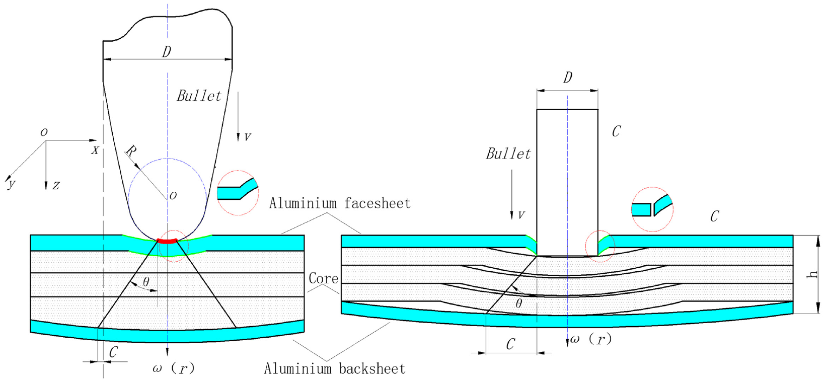
Diagrams of conical failures of the three-layer target plates.
When using the three-layer structure, the empirical formula for the broken cone half-cone angle must be modified according to the experimental results, as follows (

The bullet interacted with the target plate on impact as follows:
In stage I, a large compressive stress formed in the elastic surface plate, and the elastic body was passivated, penetrated, or broken under the action of this stress. The panel cracked under the action of the stress, the crack tip produced a large stress concentration, and the crack then extended longitudinally and laterally. At the same time, the compressive stress wave formed by the projectile body striking the panel reached the back of the panel and was reflected to form a tensile stress wave. The panel broke rapidly under the tensile stress to form a fracture zone (the fracture cone angle). At this stage, the projectile body was passivated, eroded, or fractured, and the velocity and mass of the projectile body then decreased.
In stage II, the projectile penetrated into the fracture zone (the fracture cone angle) and the fractured core layer generated a flow in a direction opposite to the impact direction, causing the panel to tear. The impact load of the projectile body was transferred through the fracture zone to the metal backplane, which bore this load and dissipated the energy through deformation and failure processes. The second stage ended when the stress wave reached the backplane and was reflected to form a tensile stress wave; the transverse crack then expanded rapidly, leading to the overall fracture. At this stage, as the projectile body’s velocity decreased, the force between the projectile body and the target plate weakened, and the projectile body then became rigid. Ceramic fragments abraded the penetrated projectile body and consumed the kinetic energy from the projectile body.
In stage III, after the target plate broke completely, the circumferential constraint of the fracture zone (the fracture cone angle) decreased rapidly and the projectile body continued to penetrate through the fracture zone with almost no constraints until the backplane was penetrated or the projectile body was blocked. At this stage, the fragments at the front end of the projectile body lost their constraint and were thus ejected. These fragments were then unable to play any further role in blocking the projectile body and their protective ability was lost. The backplane was mainly used to block penetration of the projectile body.
Conclusions
Using ABAQUS software and the VUMAT subroutine, a 3D FE model was developed based on the concept of continuum damage mechanics. In this study, the failure mechanism and the protection effects of 2A12 sandwich structures were studied under high-velocity projectile impact conditions using effective numerical models. Through experiments, four types of impact scheme were studied with flat head and R3 oval projectiles. An innovative range of damage categories caused by the different impact mechanisms were determined and summarized, and the degrees of stratified damage were observed. In addition, the damage evolution of the core laminates was predicted successfully using the strain rate-dependent continuum damage model with interlaminar cohesive elements. The following conclusions can be drawn from the experimental and numerical results:
In the high-velocity impact case, the damage pattern sequences caused by the impact could be classified into the following five types: delamination, backside fiber failure, front and rear cracks, penetrating layer cracks, and front cracks. The damage to the core layer was mostly composed of large areas of matrix cracking and layered damage accompanied by large areas of deformation. For high-speed impacts, most of the damage was extended through the layers, and the target plate was deformed slightly.
The layered area under the impact was related not only to the impact energy but also to the impacting bullet’s shape. However, in general, the delamination area increased linearly at first and then tended to become stable with increasing impact energy. Under high-energy impact conditions, the delamination area increased rapidly with increasing cumulative impact energy, and the effects of shear failure on the boundaries of the target plate were small. Under lower impact energies, the delamination area increased slowly and the damage was distributed in the fold near the rear of the plate.
In the two-layer structure with plywood acting as the backplane, the penetration performance of the flat head projectile was better than that of the R3 oval projectile. When the two bullets contacted the target plate at the same speed, more damage than deformation occurred when the sharp head of the R3 projectile struck the target plate. When the flat head bullet contacted the target plate, the damage was less than the deformation in this case; the back plate cracked, the bullet continued to move forward, and the presence of cracks reduced the bullet’s friction; therefore, for the two-layer structure, the penetration performance of the flat-head bullet was greater than that of the R3 oval bullet.
The material was sensitive to the strain rate during high-velocity impact, and the numerical model demonstrated a relatively good ability to reproduce the failure behavior, particularly in terms of the visible damage morphology and the stratified mode. For most simulation results, the error in the layered damage area was less than 10%, which was considered to be accurate for modeling of the evolution of the damaged layers.
Footnotes
Handling Editor: Chenhui Liang
Declaration of conflicting interests
The author(s) declared no potential conflicts of interest with respect to the research, authorship, and/or publication of this article.
Funding
The author(s) disclosed receipt of the following financial support for the research, authorship, and/or publication of this article: This research was funded by the Natural Science Foundation of Heilongjiang Province under Grant No. E2018001.