
Abstract
The purpose of this study was to investigate the high-velocity impact response and failure modes of three-layer sandwich panels consisting of aluminum alloy sheets and plywood. The energy absorption mechanism and interaction between the plywood core and aluminum alloy panels were investigated by a high-velocity impact test. Different types of bullets were used in the impact test, and impact velocity parameters were obtained using a high-velocity camera to assess damage patterns. A full-scale finite element model was established to simulate the response mode of plywood sandwich under high-velocity impact. After the finite element model was verified by the experimental results, the energy absorption of the sandwich structure was further discussed. The results showed that the sandwich structure provided better protection than the double-layer structure. The analysis and predictions were in good agreement with the experimental results and numerical calculations. The experimental and numerical studies proposed in this paper are expected to provide new references and ideas for the design of multilayer structures with better impact resistance and lightweight characteristics.
Keywords
Introduction
The three-layer aluminum alloy plywood core sandwich structure is composed of two high-strength aluminum alloy panels and a plywood core. This structure has the advantages of small size, light weight, and low price. At the same time, the separation of the core layer from the panel increases the moment of inertia of the whole structure without significantly increasing the weight, which enables the structure to effectively resist bending and buckling under loads.1–4 Additionally, the wood cells have high porosity and compressibility, and thus they exhibit excellent energy absorption when used in shells and structures.
One of the main limitations of sandwich composite materials is impact damage that may occur during maintenance operations or under service conditions. 5 Generally, impact failure results in structural stiffness and reduction of strength and energy absorption capacity. Existing studies have shown that the material properties and physical size of the panel and the thickness of the sandwich are important factors affecting the failure mode and energy absorption capacity of the sandwich structure. 6 A panel composed of high hardness materials undergoes elastic/plastic deformation and absorbs considerable kinetic energy under impact. However, without careful planning, simply improving the material properties and size of the metal panel places a great burden on the structure. On this basis, the exploration of new stacks of material combinations can improve the stiffness ratio and strength-to-weight ratio of sandwich plates, and the sandwich structure is considered to be the most promising alternative to traditional single metal materials. Plywood is a lightweight, orthogonal anisotropic material with high strength and stiffness ratios. Because plywood is an orthogonal anisotropic material, structural differences strongly affect the failure mode and energy absorption, 7 and the design of core sandwich structures becomes significant.
Therefore, many studies focus on the impact response of sandwich composites. Ferdous et al. 8 conducted an experimental study on the low-velocity impact and post-impact behavior of composite sandwich panels composed of braided carbon/epoxy panels and polyvinyl chloride (PVC) foam cores. Imielinska et al. 9 studied the impact damage behavior of electronic glass/polyester-PVC foam core sandwich structures by manufacturing. High-velocity photography was used to record the damage initiation and failure mechanism. John Susainathan et al. 10 studied the mechanical properties of wood laminate structures under low-speed impact, focusing on the calculation of impact damage under 5 J and 10 J kinetic energy tests. Dvorak and Suvorov et al. also conducted studies on low-speed impacts on plywood.11,12 At present, research on wood laminate plywood in sandwich structures involves primarily static and quasi-static low-speed conditions and rarely strong dynamic nonlinearity. Research mainly focused on the finite element analysis (FEA) of the response of sandwich structures6,8 to low-energy impacts. When high-velocity impact is involved, it is difficult for analytical models to predict the entire process of the response of sandwich structures. However, further research is needed on the subject.
Under a plane impact load, the front panel of a sandwich structure deforms and compresses the core material, and a limited amount of stress is transferred to the rear panel,13–16 resulting in a variety of impact damage. By introducing different sandwich structures and types of bullets in numerical simulations, some conclusions were drawn. Under high-energy and high-velocity impact conditions, the core layer exhibits strong nonlinear and high strain rate-related behavior. Although previous scholars have conducted relevant low-speed impact experiments and obtained some relevant conclusions, many questions remain unanswered. Furthermore, the latter is difficult to predict with analytical and numerical tools17–19 due to the influence of various parameters on complex interactions between failure modes.
The purpose of this study was to establish an analytical model to study the dynamic response of a sandwich panel with a composite foam panel core. The penetration process under high-velocity impact was studied. The failure mode was analyzed and studied, and the failure mode and failure area were described in detail. The dynamic Hopkinson bar impact test and quasi-static mechanical test were used to obtain the mechanical properties of plywood and wood, and the linear and nonlinear damage of plywood under high-velocity impact was studied. Various high-velocity impact experiments were conducted on the sandwich structure to obtain a complete ballistic data curve, and a full-scale finite element model was established. Multiple damage criteria20–25 were used to verify the model and predict the internal damage of the sandwich plate, thus revealing some important details of its energy absorption mechanism. The experimental results and finite element analysis validated the theoretical prediction of the peak load. The finite element simulation results showed that increasing the number of layers of the plywood core structure can obtain better protection performance.
The organizational structure of this article is as follows. In Section “Problem formulation,” the problem is described, and the penetration process is divided into three stages. The high-velocity impact response of the plywood sandwich structure corresponding to the three stages is predicted in experiments in Sections “Numerical analysis and finite element modeling” and “Experimental techniques and methods,” and the model is verified by comparison with the experimental results in Section “Results and discussion.” The relationship between the failure mode and the structure and energy absorption is discussed. Finally, we conclude the paper.
Problem formulation
The model is established as a sandwich structure of clamped square aluminum alloy panels and a plywood layer core. The three-layer structure is impacted by a cylindrical bullet with radius R, as shown in Figure 1.

Schematic diagram of the sandwich structure of aluminum alloy and plywood.
The sandwich consists of two orthogonal isotropic aluminum panels of thickness h and a breakable plywood core of thickness H. The panel material is assumed to be linearly elastic. Plywood is considered homogeneous and anisotropic, and it is modeled as a rigid fully plastic material. A hemispherical bullet with radius R, mass M and initial velocity V hits the center of the target plate. The bullet is assumed to be rigid.
The dynamic response of the sandwich plate mainly depends on the bullet impact velocity. In this case, the target plate is damaged, including local indentation and global deformation. For plywood with relatively weak core layers, local indentation and global deformation can be considered separately in the theoretical analysis.
The bullet is assumed to impact the target plate in three stages, as shown in Figure 2: In the first stage, the bullet contacts the panel, and the impact deformation is consistent with a typical penetration model. The bullet contacts the panel and produces plastic deformation, and the aluminum alloy panel absorbs a large amount of impact energy, deforms, and its temperature rises. After the panel fails, the bullet burrows into the core layer, the panel no longer resists deformation, and the first stage ends. In the second stage, the crushed panel forms a plug or Radically Invasive Bullet (RIB), and the bullet and plug move at the same speed. The side and front of the bullet continue to exert pressure on the core material and move. The back sheet becomes deformed. The second and third phases begin together. In the third stage, when the core under the bullet is completely dense and the load is transferred to the back sheet, the damage area may be different from the incident surface because of the change in boundary conditions. Finally, the back sheet breaks, and the panel is completely penetrated.

Schematic diagram of the three stages of bullet impact.
Numerical analysis and finite element modeling
Geometry, boundary conditions, and convergence
Geometry
A finite element (FE) model was established using ABAQUS/EXPLICIT techniques to simulate the dynamic response of sandwich plates under out-of-plane impact loads. The finite element model of the sandwich structure in response to a low-speed impact is shown in Figure 3.

Finite element model of the low-velocity impact resistance of the sandwich structure.
The bullet hit the target plate at a certain speed. As shown in Figure 3, the plate was 7 mm thick, the other two dimensions were 140 mm × 140 mm, and the friction coefficient between the bullet and the target plate was 0.25.
Five types of bullets were designed: (a) r3, (b) 180°, (c) 60°, (d) 90°, and (e) 120°, with a uniform diameter of 12.7 mm and a uniform mass of 38 g by controlling the length and adjusting the depth of the hollow groove at the tail. The finite element modeling dimensions and physical objects of the bullets are shown in Figure 4.

Bullet diagram.
Boundary conditions
Fully built-in (U1 = U2 = U3 =UR1 = UR2 = UR3 = 0).
A convergence study was conducted to determine the minimum element size.
Meshing
According to the established finite element model, the residual velocity and critical dimensions of failure after bullet impact were calculated. Layers and parts of the structural target plates were meshed using C3D8 R (cubic, 8-node, 3D elements, reduced integration unit) elements, which were studied in the finite element calculations. Enhanced hourglass control was enabled to prevent distortion of the elements. Double/triple sandwich structure overall cutting size 160 mm × 160 mm sandwich layer thickness of 5 mm. A j–c model hexahedral mesh was used in the finite element model of the aluminum plate, which could be deformed into a three-dimensional solid. The mechanical connection was fixed by bolts between the aluminum plate and the board layer, and the cohesive force unit was added between the core layer wood and the wood.
Through the analysis of the convergence of the finite element model of the aluminum alloy plate and plywood core layer, the mesh size was determined by a large number of mesh sizes. The mesh sensitivity study showed that the element size of 0.25 mm could provide a good balance between the simulation accuracy and efficiency. The calculation of residual velocity under the impact of an R3 bullet at 100 m/s is shown in Figure 5.

Mesh sensitivity analysis.
The internal stress and strain of the sample under impact were studied. The experiment showed that there was no damage, mass shedding or obvious deformation of the bullet in the experiment, and the heat treatment significantly improved the hardness of the bullet compared with that of aluminum plate and new wood board. Therefore, the bullet was set as a rigid body to reduce the number of calculations. The study involved high-velocity impact, and the process used for the simulation was Dynamic/Explicit. According to the actual division, the grid properties of the impacted target plate are shown in Table 1.
Finite element meshes for laminated plates.

The definition of the contact algorithm was the most fundamental part of the finite element analysis of the impact/contact problem. Three types of contact algorithms were used to model various contacts that influenced the conditions during the collision process. Erosion contact types were calculated through the keyword options and contact definitions of the model in ABAQUS. Depending on the material differences between different laminations of the sample, the choice of different parameters and settings was key to the model calculation when defining internal contacts. The system program allowed the remaining elements inside the sandwich plate to continue the contact operation after a failed element was removed by external bullet penetration.
Material models
The composite sandwich structure was built with anisotropic tiling and a j–c model. The experiments show that the surface damage of 2A12T4 was mainly plastic deformation and tensile fracture failure in the impact region. Referring to the research of Hou et al., 26 the adjustment of 2A12T4 was made by adopting the J-C model, and the failure model27,28 was defined as follows: The equivalent fracture strain was:


where
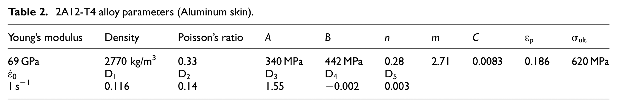
The parameters of the aluminum alloy are shown in Table 2.
2A12-T4 alloy parameters (Aluminum skin).
In the case of a high-velocity impact, the composite element was mainly loaded by transverse compression of the main shear component when compression is dominant. The failure was assumed to be governed by the maximum (critical) elastic shear strain in the interfiber matrix, while the strain constraint along the fiber was zero. In the case of shear dominance, the composite element was mainly loaded in an in-plane shear with an undominant compression component. It was assumed that failure was controlled by the maximum (critical) elastic tensile strain between fibers and that the strain component of the fibers was constrained. In the case of tension, the composite element was mainly loaded in tension with the nondominant shear component. It was assumed that failure was controlled by the maximum (critical) elastic tensile strain in the interfiber matrix and that the strain component along the fibers was constrained. 29 The behavior of the wood under tension was brittle, while in compression perpendicular to the grain, the wood exhibited plasticity and could therefore be modeled accurately by the Hashin damage criterion.30,31
Hashin damage criterion


where subscripts 1, 2, and 3 represent coordinate directions, where 1 is the fiber direction, 2 is the direction perpendicular to the fiber direction in the laminate surface, and 3 is the thickness direction of the laminate overlay.
Finite element mesh and cohesive layer behavior
The sandwich was modeled as a composite material, and a cohesive tensile traction model was added. The panel and sandwich were mechanically connected and bonded. The lamination of sandwich plywood was controlled by Hashin criterion cracking failure fracture. According to the measurements and literature, 32 an integral thickness was present between the cohesive force model and wood. The thickness was defined as 0.1 mm. Damage of sandwich structures and delamination and debonding between layers were assumed to be controlled by failure criteria33,34; the plywood stress–strain curve is shown in Figure 6(c). Equations (8a) to (8c) describe the linear elastic behavior of the traction-separation model. When the quadratic function defined in (3) reached a value of 1, damage was assumed to begin. Figure 6(b) shows the dependence of modal mixing on damage initiation and evolution of the tractor-separation response of isotropic shear behavior. The traction-separation law of cohesive elements is shown in Figure 6(a):

Linear damage and stiffness degradation of plywood and the cohesive element model: (a) Plywood stressã strain curve, (b) mixed-mode response, and (c) typical traction-separation response.
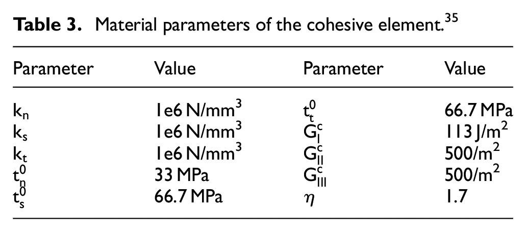
The model parameters of the bonded zone are shown in Table 3.
Material parameters of the cohesive element. 35
The Benzeggagh and Kenane-kenane fracture criterion 36 was implemented, and its expressions are shown in equation (11).


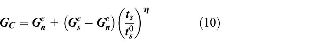


where
Experimental techniques and methods
Different impact velocities lead to different failure mechanisms. Low impact velocities mainly cause local penetration and overall structural response of sandwich panels; medium impact velocities may cause both local penetration and overall structural response of sandwich panels; and high impact velocities mainly cause penetration and negligible structural response of sandwich panels to some extent. The hardness and rigidity of the bullet material are typically much greater than those of the sandwich structure. In the experiment, the impact model of the sandwich structure composed of a 1 mm aluminum alloy plate and 5 mm plywood was simplified as the process of rigid bullets hitting thin plate targets. In this case, only a single failure mechanism was considered, such as disc diffusion, ductile reaming, adiabatic shear, punching plug, bending, or stretching.
Material parameter properties
The purpose of this experiment was to investigate the failure mode of plywood when it was penetrated in two kinds of laminated structures. The specific production of samples was divided into two types: (1) Double-layered samples were constructed from aluminum alloy as the panel and plywood as the second back sheet. (2) Triple-layered samples were constructed from aluminum alloy as the panel and back with plywood as the core layer
The aluminum sheet metal served as the strength and damage resistant surface layer, and the plywood served as the core filling to provide stiffness and impact energy absorption of the interlayer. Plywood is a multi-layer adhesive composite made from spin-cut sheets of wood, orthogonally tiled and held together by an adhesive that homogenizes the strength properties of the wood and produces greater shear resistance and good splitting resistance. Plywood with a thickness of 5 mm was selected and cross-laid to make tensile samples. A 100 kN multifunctional electronic tensile machine was used to conduct quasi-static testing at a tensile rate of 10 mm/min. Tensile, pressing and three-point bending experiments were conducted to obtain material static parameters. The obtained poplar parameters are shown in Table 4.
Initial aspen wood parameters (wood and composite plies).

Compared to a single wood, plywood structures have better physical properties due to the better mechanical behavior of the material. To develop a new structure and compare configurations, we used two different plywood layers and structures. Melamine urea formaldehyde (MUF) resin was used for poplar plywood, and the stacking sequence is shown in Table 5.
Stacking sequence.

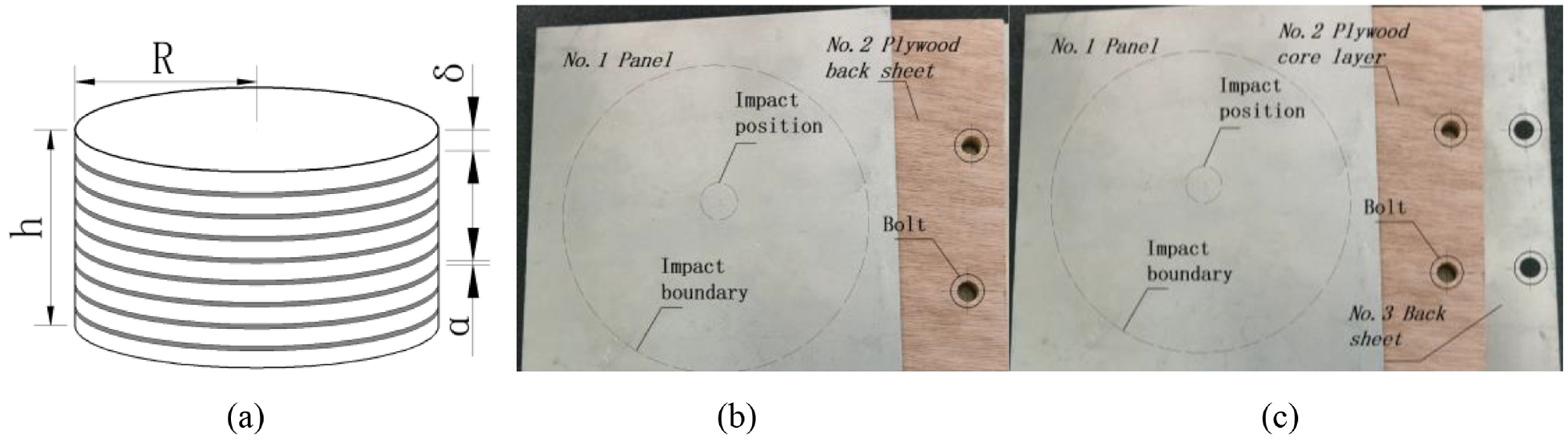
The sample size was 140 mm × 140 mm × 7 mm, and the surface was drilled and polished for easy installation. 2A12T4 as the panel cover and core material for fixed installation. The density of plywood is 400 kg/m3, and the thickness was 5 mm. The plywood was a three-layer structure with orthogonal laying of poplar plywood, and the strength of the fiber was 60 MPa in the direction of length, 7 MPa in the direction of transverse direction and 5 MPa in the direction of thickness. A moisture content of 9% under laboratory conditions was measured by a dedicated drying instrument. The impact sample installation is shown in Figure 7.
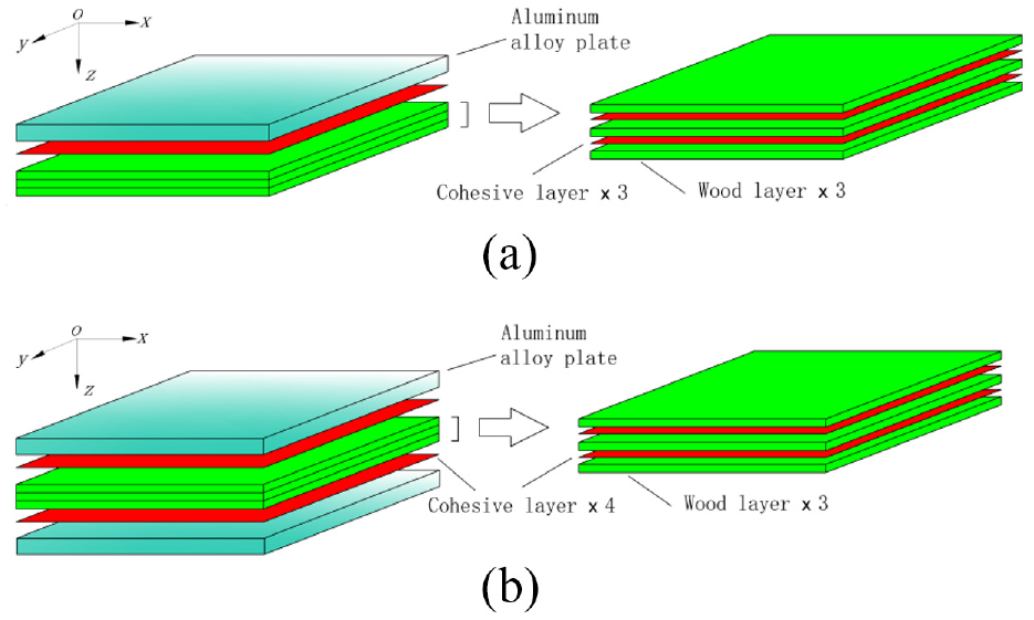
Schematic diagram of sample making: (a) schematic diagram of the double-layer structure; (b) schematic diagram of the three-layer structure.
The core layer of plywood in the sample was laid orthogonally with three layers of wood, and the angle of each layer of fiber is shown in Figure 8.

Fiber angle of the core layer: (a) schematic diagram of the double-layer structure; (b) Schematic diagram of the three-layer structure.
The mechanical experiment with core material under high strain rate load under high-velocity impact was very complicated, so the dynamic compression experiment under normal temperature was conducted. Dynamic mechanical property data were obtained to provide reliable data and a basis for the analysis and study of experimental results and numerical simulation. Based on one-dimensional stress wave theory, a dynamic loading test of plywood was carried out. The Hopkinson sample production is shown in Figure 9(a). In the experiment, the impacted core material was made of three layers of plywood with a total thickness of 5 mm.
Schematic diagram of the experimental samples: (a) Hopkinson pressure bar impact sample; (b) two-layer structure; (c) three-layer sandwich structure.
To obtain the dynamic compression waveform, the size of the Hopkinson impact pattern fabrication requires the original piece impact sample of thickness h and radius
The dynamic strain rates of materials were obtained by high-velocity impact experiments with multiple groups of samples at different incident velocities. By analyzing and processing the waveform and voltage amplitude of sensor data, incident wave

Experimental data for the Hopkinson pressure bar: (a) Hopkinson experimental setup and sample; (b) Hopkinson pressure bar waveform; (c) Stress–strain curve of the Hopkinson pressure bar.
High-velocity impact test
The high-velocity impact test device is shown in Figure 11. The experiments were conducted in the high-velocity impact laboratory of the Harbin Institute of Technology and the precision gas bearing laboratory of Northeast Forestry University. The overall device used in the experiment consisted of four parts: gas storage tank, gas gun, impact protection chamber, and high-velocity camera system. Bullet speed was measured, and impact was analyzed using a high-velocity camera (frame by frame analysis), through the frame rate and pixel point calculation of bullet speed. Air was supplied to the air storage bin by a high-pressure air pump, and the value could be observed by a pressure gauge. The test firing and ballistic calibration were conducted, and the corresponding relationship between the calibrated air pressure and bullet was convenient for subsequent experimental control. The high-pressure gas was stored in the gas storage chamber until the pressure was stable. Actuate valves and trigger cameras were used to capture images of the impact. The air pump and air storage tank could provide 0–10 MPa adjustable pressure. Bullet production was performed using CNC machine programing, and carbon steel turning processing, then heat treatment for Rockwell hardness of 58HRC. Bullets were fired from the barrel of the gas gun that was anchored in the center of the laboratory by an impact sandwich plate that was separated by bulletproof glass on both sides to ensure safety and transparency for the camera to collect data. The barrel diameter was 12.7 mm, and the length was 1.8 m. The control valve was manually controlled by a spherical valve. The camera mode was 0.5 s, the resolution of the high-velocity camera was 1024 × 768 frames, and the number of frames was 12,000 fps/s.

High-velocity experimental device.
Results and discussion
This section analyzes the impact response of the sandwich structure and each component and studies the energy absorption mechanism of plywood sandwich structures with different combinations of layers.
Data analysis
For aluminum alloy ductile metal penetration, kinetic energy consumption was mainly used to balance internal work dissipation. When cylindrical cavities are used for approximate ductile reamings, the sandwich plate is idealized as multiple thin layers independent of each other and perpendicular to the direction of penetration. The surface is the equation proposed by Lambert and Jonas for
where
values.

The experiments were numbered: A1 bullet R3 impact on a double-layer panel, A2 flat head bullet impact on a double-layer panel, A3 bullet R3 impact on a three-layer sandwich panel, and A4 flat head bullet impact on a three-layer sandwich panel.
The experimental velocity and residual velocity of impact are shown in Tables 7 to 10. Four tests were conducted on the 5 mm double-layer and three-layer samples with oval bullet R3 and flat head bullet, respectively, and the impact velocity and the remaining velocity of flight were obtained by frame number images. The impact image is shown in Figure 12.
Experiment A1 bullet R3 impact on a double-layer panel.

Experiment A2 Flat head bullet impact on a double-layer panel.

Experiment A3 bullet R3 impact on a three-layer sandwich panel.

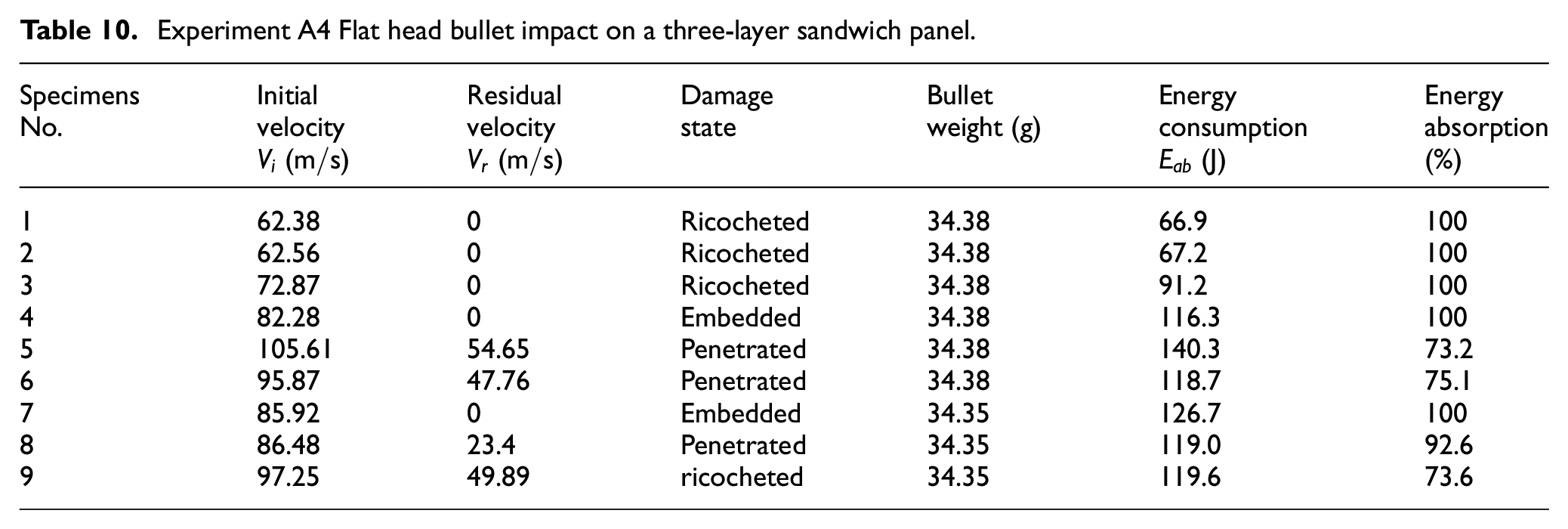
Experiment A4 Flat head bullet impact on a three-layer sandwich panel.
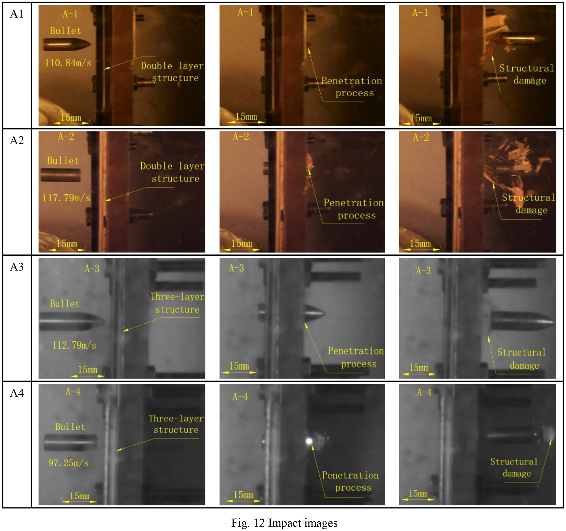
Impact images.
Different bullet speeds were obtained in the experiment to form a clear data gradient in the analysis. Setting the velocity value of different gradients could more intuitively and accurately obtain the ballistic limit of materials. The kinetic energy possessed by the bullet before impact was transferred to the target plate, causing the bullet to slow after impact. The energy absorption

The impact experimental velocities and residual velocities are shown in Tables 7 to 10.
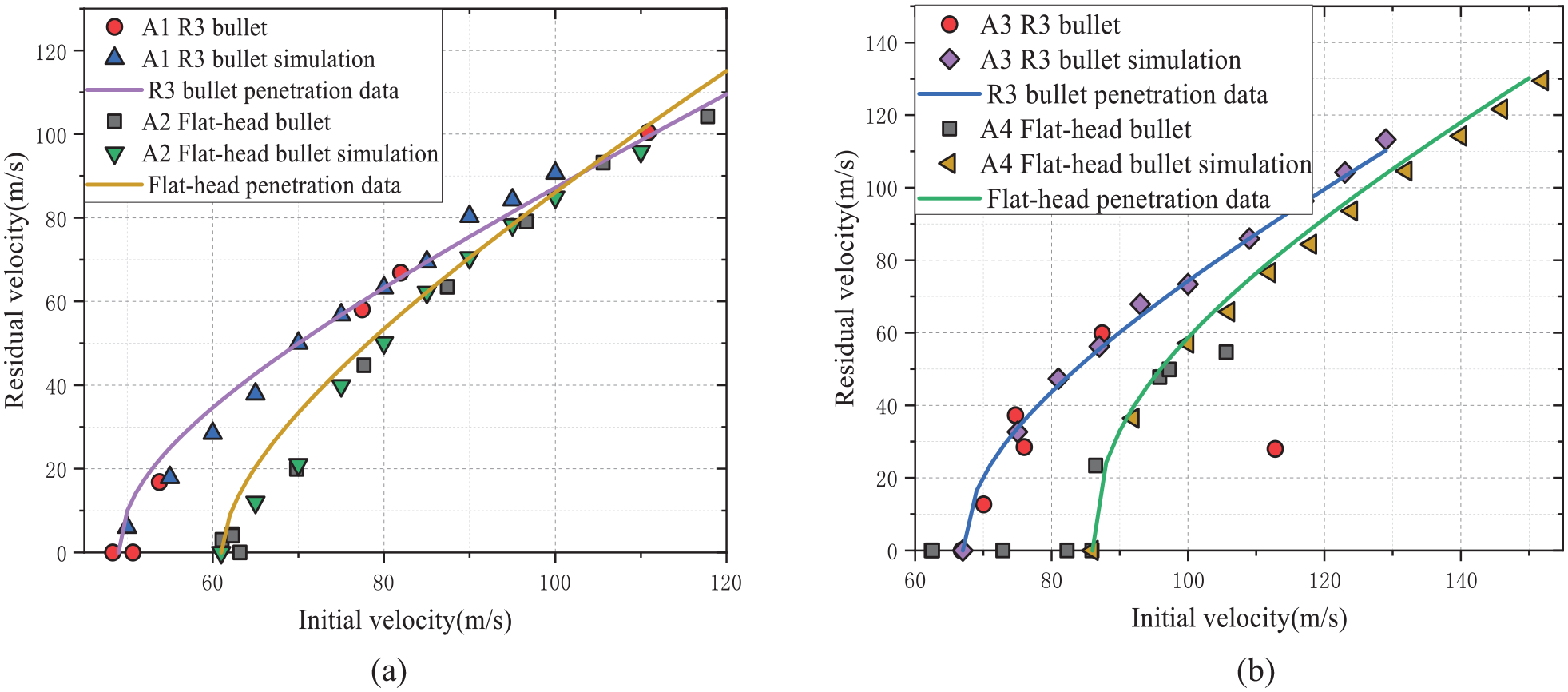
According to the penetration image and impact type, there were three cases: penetrated, ricocheted and embedded. According to the velocity bullet mass data in the Tab, the energy absorbed by the sandwich plate was calculated, and the velocity curve was drawn, as shown in Figure 13(a) and (b).

High-velocity impact experiment data: (a) ballistic data of the impact on the double-layer sandwich plate (b) ballistic data from the impact on the three-layer sandwich plate.
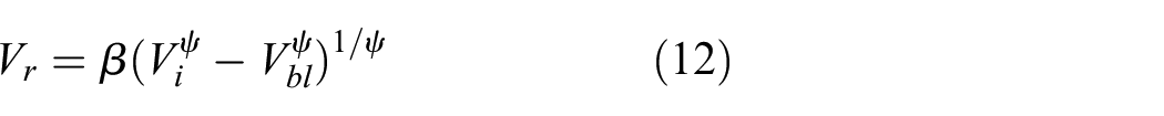
According to the experimental data and equation (12), ballistic limit curve fitting was conducted. Finally, according to the energy analysis of the image, the ballistic limit against Bullet R3 was 49 m/s, and the flat head was 61 m/s for a 5 mm back sheet with a double structure. In a double-layer structure with 5 mm plywood as the back sheet, the average breakdown energy of Bullet R3 was 30 J and that of the flat head bullet was 66 J. The ballistic limit of the three-layer neutron bullet R3 was 67 m/s and that of the flat head was 86 m/s. The average penetration energy of Bullet R3 was 76 J, and the average penetration energy of the flat head bullet was 126 J.
Global response analysis
The most obvious result of an increase in the number of protective layers is the need for a bullet with a greater firing velocity.
In the double-layer structure, the aluminum plate used as the panel had a certain hardness and toughness, which mainly helped it withstand complex stress, and the plywood plate as the back sheet was mainly responsible for giving the aluminum plate a certain stiffness. In the process of impact, the panel aluminum alloy was mainly subjected to tensile stress and shear stress, and the back sheet was mainly subjected to tensile stress. Bullet R3 penetrated the plywood back sheet mainly in the form of cracking extrusion, which was manifested as large cracks and large strain flowering. The gentle impact of the flat head on the aluminum alloy was mainly caused by edge shear failure, while the back sheet plywood was caused by plug failure.
The three-layer structure was more complex than the double-layer plate in terms of structure. The presence of an aluminum alloy backplate as a boundary condition limited the displacement of the thickness in the z-direction of the sandwich to a certain extent when it was impacted, which resulted in the difference between the sandwich and the double-layer structure during failure due to stress damage. The bullet penetrated the target plate, as shown in Figures 14 and 15.
(A1) According to high-velocity camera observation, in the double-layer structure, the panel was hit by bullet R3. At this time, the bullet was moving fast, the panel bore the impact force, and the tip of the bullet penetrated into the first layer. At this point, the damage was many tiny hose, the bullet continued to penetrate into the panel, and friction with the bullet produced a petal phenomenon. Experimental observation showed that four petal-like lesions were produced. The bullet continued deep into the second layer of plywood, which was then squeezed by the metal at the back and struck by the bullet. The velocity of the bullet was greatly reduced, and the subsequent impact damage was mainly caused by the stress concentration due to the scratch on the damaged aluminum plate. In addition, fiber tensile failure, shear failure, and unique layered failure of the sandwich structure were caused by the impact of the bullet.
(A2) It was expected that when the flat head bullet hit the double-layer structure, the contact between the flat head bullet and the panel should be a circular plane. The collision between the bullet and the panel produced plastic strain when the panel was impacted, and the bullet continued to advance and generate a shear circle around the bullet and the panel. The bullet continued to strike deeply into the second layer of plywood. In the experimental sample, the flat head bullet impinged on the back sheet, which mainly produced tensile damage.
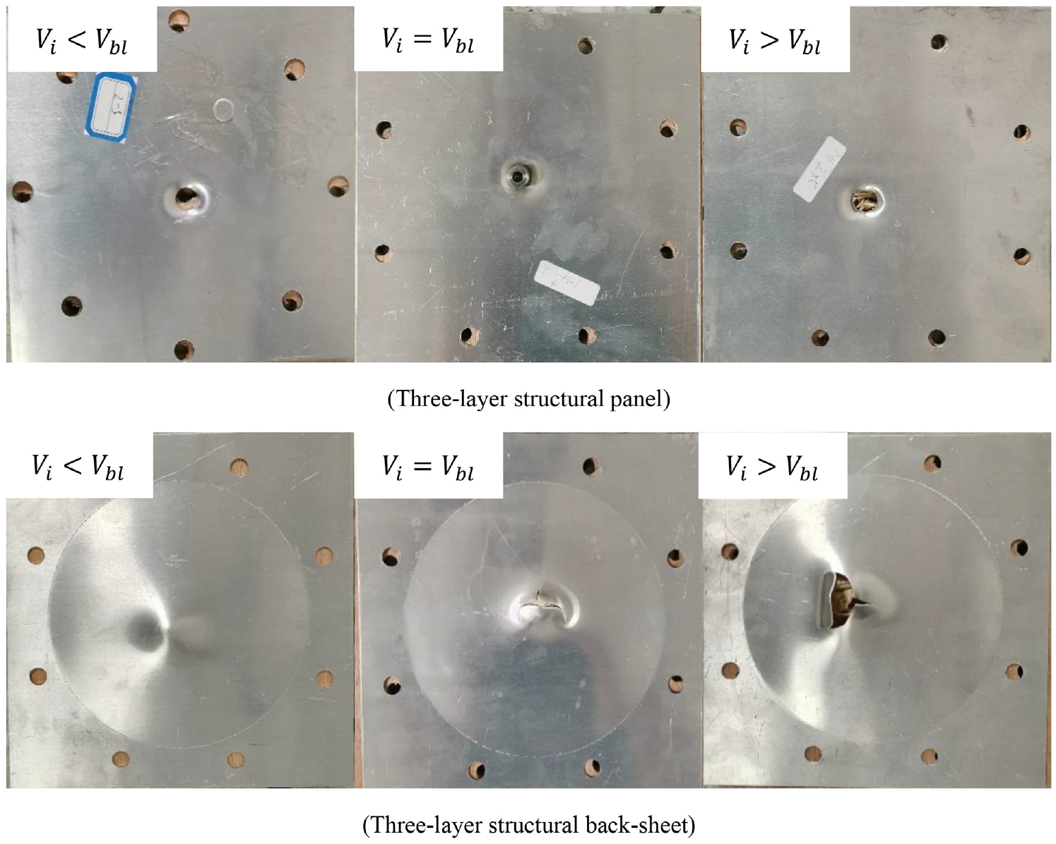
(A3) When the R3 bullet impinged on the three-layer structure and the aluminum alloy was the back sheet, compared with the double-layer structure, the bullet velocity was further reduced mainly due to the plastic deformation caused by the extrusion of the damaged interlayer and the tensile damage caused by the bullet impact. At this time, the stress of the back sheet was extremely complex and varied, and the most important manifestation was that the strain of the back sheet showed overall large strain and local tensile failure. The raised part of the back sheet was further pushed by the bullet and continued to deform. The tensile stress of the raised part exceeded the tensile strength of the material, and star cracks were generated around the top of the bullet. It was observed that R3 bullets did not cause shear damage when penetrated.
(A4) In the process of the bullet penetrating the target body, the core material was damaged layer by layer and underwent deboning layer by layer. The stress wave and energy generated by impact spread layer by layer between the wood layers, showing a horn shape in the thickness z-direction. The bullet continued to move, and wood fibers were cut off by the impact, resulting in slip dislocation and compaction. At this time, part of the core material slid around the bullet by extrusion, and the remainder continued to move down under pressure to compress the back sheet. Under the buffer action of the core material, the back sheet increased the force required for shear failure, and the back sheet absorbed more kinetic energy than the panel in the penetration failure.

A3 Experimental image of bullet R3 impact. (Three-layer structural panel) (Three-layer structural back-sheet).
A4 Experimental photographs of flat head bullet impact. (Three-layer structural panel) (Three-layer structural back-sheet).
There was an enormous difference in the damage mechanisms between R3 and the headshot. The sample model was simplified as a thin plate target. When the bullet penetrated the target, it produced ridges and disc depressions. After breakdown, friction between the bullet and the target generated heat. In the study of thin plate targets, the ballistic velocity was relatively slow because the target was too thin, which resulted in the narrow zone where the phase changed occurred in the target plate.
The front and back of the three-layer sandwich structure covered the middle part of the aluminum panel with 5 mm thick plywood as the sandwich to provide stiffness retention and act as a buffer filler. The double-layer aluminum plate itself had very good strength and impact resistance, and the presence of the gap increased the impact resistance of the aluminum plate to a certain extent. In the process of bullet impact, the mainly the back sheet bore the tensile/shear damage, and the core layer was squeezed to cause fiber failure. At the same time, it was subjected to shear damage when the bullet contacted the edge of the sandwich plate. The impact is visible ins a photograph of the deformation/failure mode of the baseline panel, as shown in Figure 16 below.
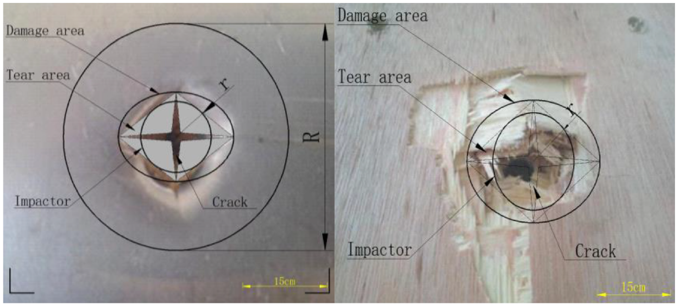
Photographs showing deformation/failure modes of the baseline panel.
Finite element model verification
The calculated results were compared with the results obtained from the experiments for numerical verification. The calculated results were compared with the experimental results for numerical verification. The modeling results are shown in Figures 17 and 18.

Stress cloud diagrams of bullet R3 impacting the three-layer sandwich panel.

Stress cloud diagrams of a flat head bullet impacting a three-layer sandwich panel.
Most of the details of the deformation/failure modes observed in the experiments were captured by the results of the proposed FE model. The results showed that the predictive ability of the developed FE model was acceptable. The impact simulation was performed using ABAQUS software. The incident velocity was set according to the experimental data. The corresponding residual velocity was obtained at different incident velocities. Using the incident velocity of 100 m/s as the benchmark, the calculation results are shown in Table 11:
Comparison of experimental and simulation results.

The error between the finite element results and the experimental results was within the acceptable range of 4%. The comparison of the results of the penetration velocity models is shown in Figure 19.
Comparison of model and experimental data: (a) ballistic data model verification of impact on double-layer sandwich plate; (b) ballistic data model verification of impact on three-layer sandwich plate.
Forecast of peak load
Further comparison of penetration data for the double-layer plate and the three-layer plate, with 5 mm plywood as the core material and back sheet, showed differences in not only the failure form but also the strength performance. Plywood is required to withstand a portion of the shear damage in a structure. In the three-layer structure, the aluminum alloy back sheet provided additional stiffness to the core material, and thus the proportion of shear damage to the plywood increased sharply. Because the plywood had a certain elasticity, part of it was damaged during the impact process, and the remaining tip part was compacted. Compared with the two-layer structure, the core material was particularly strengthened during the impact of the flat head bullet, with a shear strength increase of 400% and a strength increase of 200% during the impact of the R3 bullet.
Due to its unique circular arc shape, the increased penetration of bullet R3 also reduced the friction between the bullet and the target plate, and the frontal action range was 38 mm when it hit the target plate. As seen from the straight lines in Figure 19(a), the bullet had very little influence on the overall structure of the layer and the structure. As shown in Figure 19(b), the maximum displacement of adiabatic shear generated by the high-velocity impact between the flat head bullet and target plate was generated at the edge of the bullet body; the friction force was large, and it had a large effect on the edge of the panel during the impact. The impact generated a circular plastic deformation area with a diameter of 90 mm at 30–120 mm, which consumed much of the kinetic energy of the bullet. In both Figs, the peak load occurred at the center of impact, and the load of the flat head was six times that of the R3 bullet. The load-position and displacement-position curves are shown in Figure 20.

Load-position and displacement-position curves: (a) flat head bullet impact (b) R3 bullet impact.
Core energy absorption
The data analysis shown in Figure 19 proves the validity of the finite element model developed in this study. Therefore, the model can be used to further explore the complex energy absorption mechanism of sandwich plates under impact loads. Figure 24 shows that the kinetic energy dissipation of the bullet was transformed into four parts, namely, the internal energy of the plywood, the internal energy of the upper and lower parts, and the friction energy between the surface and core components. In the first stage, the topmost panel played a key role in energy dissipation because friction work absorbed very little energy. In the second stage, the work done by friction increased rapidly and became a major part of the energy dissipation mechanism. In the dynamic stage, due to the large plastic deformation, the energy absorbed by the bottom surface increased. To further study the energy dissipation mechanism under different impact loads, the dissipation ratio of the panel, back sheet and core layer is shown in Figure 21.

Energy conversion versus time for samples under 174 J (100 m/s) impact energy: (a) A1, (b) A2, (c) A3, and (d) A4.
Under high-velocity impact, as shown in Figure 20(a), experimental sample A1 generated strain as a whole, and the top panel absorbed 82% of the total kinetic energy of the bullet, while the plywood backplane absorbed 18% of the total kinetic energy when the bullet broke down. As shown in Figure 20(b), in experiment A2, the top panel absorbed 58% of the total kinetic energy of the bullet, while the plywood backplane absorbed 42% of the total kinetic energy when it was punctured. The aluminum alloy in the panel played an important role in resistance to bullet impact in the double-layer structure with high-velocity impact, and the strength of the panel should be increased when designing the double-layer structure.
As shown in Figure 20(c), in experiment A3, the top panel absorbed 58% of the total kinetic energy of the bullet, while the backplane absorbed 34% of the total energy when breakdown occurred, and the plywood core layer absorbed 25% of the total kinetic energy. As shown in Figure 20(d), in experiment A4, the kinetic energy absorbed by the top panel was 25.5% of the total bullet, the backplane absorbed 40.5% of the total when the breakdown occurred, and the plywood core layer absorbed 34% of the total kinetic energy. It indicated that the strength of the top panel and the back panel should be strengthened to resist impact by a sharp projectile in the case of high-velocity impact on the third layer. To resist the impact of flat head shells, the core layer and the back plate should be strengthened.
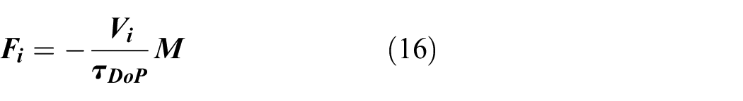
The Haque-Gillespie
38
energy based depth of penetration model predicts a linear relationship between the penetration depth

Where,

Where,

Relationship between characteristic time and penetration velocity.
The characteristic time
Xie et al. 39 proposed an analytical model to obtain the ballistic limit of sandwich plates under high-speed impact loads. The model consists of providing an energy balance between different kinetic energy components:

where,
To compare the results of the experimental, numerical and theoretical analyses more intuitively, the three-dimensional response surface of the peak load was sliced to generate a two-dimensional graph. Within the scope of this study, the theoretical predictions achieved good consistency. The software algorithm automatically deleted many distortion units during the simulation, which resulted in some deviations from the actual results. In general, the theoretical model and finite element model agreed well with the experimental results, and the model can be used for the design of sandwich structures. The simulated impact is shown in Figure 23.

Simulation of impact of different bullets: (a) r3, (b) 60°, (c) 90°, (d) 120°, and (e) 180°.
Increasingly complex impact types can be studied according to the established finite element model. Various impact experiments can be simulated very efficiently by setting the bullet head at different taper lengths and speeds. In the model, the limitations of machining accuracy and machining quality can be ignored, and the impact of bullet speed, mass, taper and impact effect can be studied more accurately and objectively. Five kinds of bullets were designed in the simulation: R3, flat head, 120° angle bullet, 90° angle bullet, and 60° angle bullet. Two-layer and three-layer structures were simulated. According to the above experimental results, to ensure that the bullet penetrated the sandwich panel, the impact velocity was set at 100 m/s. The calculation results are shown in Figure 24:

Simulation results for impacts of bullets with different types of head.
At an impact speed of 100 m/s, the penetration performance of the warhead at angles of 60°, 90°, and 120° was relatively similar, and the damage caused was similar. The front panel was damaged by bullet impact, and the core material and the back plate were extruded until they were penetrated. The core material mainly bore shear extrusion damage. When the angle of the flat head was 180°, a sharp cutting blade formed around the bullet contour with increasing speed, and the sandwich plate was cut and separated into circular pieces similar to the bullet contour. The residual velocity tended to be stable at 0.45 ms. Further study of the developed finite element model showed that, at the same speed, with the decrease in bullet angle, the damage to the front panel also decreased.
The study conducted using the finite element model showed that the ultimate ballistic velocity of the R3 bullet hitting the double-layer aluminum alloy plate without an added core layer was 82 m/s. According to equation (13), the contribution of the core layer to energy absorption was 32%.
To compare the results of the experimental, numerical and theoretical analyses more intuitively, the three-dimensional response surface of the peak load was sliced to generate a two-dimensional graph. Within the scope of this study, the theoretical predictions achieved good consistency. The software algorithm automatically deleted many distortion units in the simulation, which resulted in some deviations from the actual results. In general, the theoretical model and finite element model agreed well with the experimental results, and thus, the theoretical model can be used for the design of sandwich structures.
Conclusions
In this paper, two kinds of protective structures composed of aluminum alloy and plywood were studied by experimental and numerical methods. Quasi-static and Hopkinson dynamic experiments were performed to obtain the mechanical property parameters of the materials, two kinds of bullets with a diameter of 12.7 mm were used to conduct impact experiments on the target layer and structure, and the mechanism of enhanced impact resistance caused by different combinations of materials was discussed. A full-scale finite element (FE) model was developed to replicate the response of plywood sandwich panels to high-velocity impacts. The following conclusions can be drawn.
At a high strain rate, the plywood core layer became stronger due to compression. Under high-velocity impact, the energy absorption performance of the assembled sandwich plate was much better than that of a single material. Therefore, when assembled into a sandwich form, the utilization efficiency of the material can be improved.
The impact response and energy absorption of plywood improved when aluminum alloy layers were superimposed on the front and back of the plywood. The high-strength aluminum alloy was impacted, and energy was transferred to the interior, which was composed of a brittle wood layer. Extensive matrix fracture and fiber damage in the brittle interlayer were the main modes of energy absorption.
Finite element models of aluminum alloy and plywood core sandwich panels were developed and compared with experimental results in terms of penetration depth and influence of bullet shape. A theoretical model describing the correlation with penetration velocities was then developed, and the associated limiting velocities were compared with numerical results, showing reasonable agreement.
In terms of the damage mechanism, aluminum alloys can effectively improve impact damage resistance due to their toughness and isotropy. The failure mechanism of the structure affected by bullet impact was mainly characterized by local fracture of the upper panel, fiber fracture of the core layer, matrix and interlayer cracks, and tensile shear fracture of the back plate. In addition, the shape of the bullet head had a significant impact on the impact response of the sandwich structure.
This study showed that the number of stacked layers of sandwich plates can provide a solution to improve the overall mechanical properties under ballistic impact. However, more studies of stacking and materials are needed to determine the optimal design of sandwich panels.
Footnotes
Handling editor: Chenhui Liang
Declaration of conflicting interests
The author(s) declared no potential conflicts of interest with respect to the research, authorship, and/or publication of this article.
Funding
The author(s) disclosed receipt of the following financial support for the research, authorship, and/or publication of this article: This research was funded by the Natural Science Foundation of Heilongjiang Province, Grant No. E2018001.