
Abstract
This work presents an experimental and theoretical study on the punching shear behavior of Lightweight Concrete Slabs. Lightweight obtained using Expanded polystyrene (EPS) beads as partial coarse aggregate’s replacement, without adding supplementary bonding additives, to reduce concrete density from 2400 to 1800 kg/m3. The EPS content, concrete strength and column aspect ratio were test parameters. Five groups of concrete prepared by partially replacing natural coarse aggregate with 0%, 10%, 20%, 30% and 40% (by volume) of EPS balls. Ten reinforced concrete slabs without shear reinforcement with a monolithic column were tested under concentric loading. The study aimed to examine the effect of the EPS on the density and compressive strength of concrete and eventually on the flat slabs punching capacity. Five series of mixtures identified and compared with conventional normal weight concrete. Results showed that with increasing EPS content, rate of reduction in concrete strength is faster than the reduction in concrete density. Also, showed that the failure base area increased while the concrete density decreased, this yielded a higher punching capacity compared to rate of decrease in the concrete strength. International standards models showed overestimation of punching shear capacity and didnot reflect the reduced concrete strength action of lightweight concrete.
Originality/Value
The paper is the first attempt to explain and illustrate the punching behavior of EPS concrete flat slabs without shear reinforcement or concrete additives.
General
Expanded polystyrene (EPS) concrete is a kind of lightweight artificial aggregate concrete that uses EPS particles as coarse aggregates which gives the concrete its lower density by increasing its porosity and by its lower apparent specific gravity, Neville and Brooks. 1 EPS is an extremely lightweight product that is made of EPS beads which are more than 95% air and only about 5% plastic, Todd. 2 However, the high thermal resistivity of the concrete and the acoustic insulation and some of its desirable properties result from the presence of these beads, Kuhail. 3 Using EPS is more economical compared to normal concrete and producing EPS concrete without a special bonding agent shows good workability and can easily be compacted and finished and the replacement by using EPS has shown a positive application as an alternate material in building nonstructural members, Abhijit et al. 4
Perry et al., 5 stated that the mix proportions of the EPS concrete in most investigations was performed by replacing aggregates with EPS beads on a volumetric basis to reduce the concrete weight including the wide range of replacement levels for either or both fine and coarse aggregates and different trends (linear or logarithmic) of the effect of replacement levels on the mechanical properties.
Robert et al., 6 in their study aimed to achieve a mix design for Lightweight EPS Concrete with density less than 1800 kg/m3 but with enough compressive strength to be used in construction purpose. They stated that the mechanical properties of EPS concrete is differ than ordinary LWC since the stress distribution within a granular cement-based composite depends on the sizes of the inclusions and on the respective modulus of the matrix and of the inclusions. When the aggregate has a modulus higher than that of the matrix, stress concentrations appear in the vicinity of the aggregate. However, when dealing with a very lightweight aggregate, like EPS, having a negligible modulus, the two-phase models are at their limit of applicability. Another way is to refer to models based on porosity, assuming that the concrete is described as a matrix containing voids (EPS spheres).
Al-Mamoori et al. 7 in their attempt to produce structural lightweight concrete by using three locally available types of lightweight aggregate from different sources of local natural, waste and recycled materials in Iraq, showed that in LW aggregate concrete, it is necessary to relate the density with the mechanical properties prediction equations for more accuracy when compared with formulas of ACI-318. The study showed in LWC there is a liner relation between cube and cylinder strength (f’c/fcu) which ranged between (0.834 and 0.846) with an average of about 0.84, which is adopted in this study.
Yang et al. 8 prepared flat slabs using three types of concrete; all-lightweight aggregate concrete (ALWAC), sand-lightweight aggregate concrete (SLWAC) and normal-weight concrete (NWC) with different compressive strengths of 24 and 45 MPa. The aim of the study is to examine the effect of the unit weight and compressive strength of concrete on the punching shear capacity of flat slabs without shear reinforcements. Based on the upper-bound theorem of concrete plasticity, the failure surface generatrix is generalized to account for the increased horizontal extension with a decrease in the unit weight of concrete. The punching shear capacity of concrete flat slabs is mathematically driven considering the reduced effective strength of lightweight aggregate concrete under tension and compression. They proposed a model based on a lower normalized punching shear capacity they observed for ALWAC and SLWAC flat slabs than NWC flat slabs.
Mohamed et al., 9 stated that the flat slab popularity is owed to the ease, flexibility, speed of construction, and its considerable ability to transfer vertical loads through membrane action. Yet, in the event of loss of primarily load-carrying system, the potential for progressive collapse is relatively high. They stated that the reason for this progressive collape is the lack of alternate load path to transfer gravity load. Their work discusses the dominant failure modes associated with the progressive collapse in flat slab construction and produce suggestions for geometric and structural design of flat slab system that will enhance resistance for progressive collapse with better life safety such as use of enhanced local resistance approach for corner and penultimate columns, use of edge beams along perimeters and other solutions including detailing anchorage of bottom reinforcement through columns.
Experimental program
Materials
Ordinary Portland cement (type I) was used in this study and it was conformed to the Iraqi Standard (IQS No. 5, 1998). 10 The cement was manufactured locally in Sulaimani city in Northeast Iraq. The fine and coarse aggregates used in this study were obtained from local sources. The local river sand used had a maximum fine aggregate size of 4.75 mm, specific gravity of 2.67 and finesse modulus of 3.2 while the gravel used has a normal maximum size of 9.5 mm (max. aggregate size = 12.5 mm) and a specific gravity of 2.7. Tap water was used, it was clear and clean. Since EPS is hydrophobic, the concrete water absorption is zero even when the beads are immersed in water continuously for a month, thus beads were not taken into account in mix proportion, Abhijit et al. 4 Welded steel wire mesh of diameter 4 mm with spacing of 50 mm in centers in both directions to reinforce the slab at the tension face keeping 10 mm cover. The yield strength of the wires was 420 MPa as reported by the manufacturer. The EPS beads used were obtained from Hemn Group Factory in Khabat, Erbil, Kurdistan-Iraq, shown in Figure 1. A type of commercially available spherical EPS beads with a maximum size of 8.0 mm. The grading shows that the EPS beads size ranged between 5.0 and 8.0 mm with bulk density was 5.5 kg/m3.
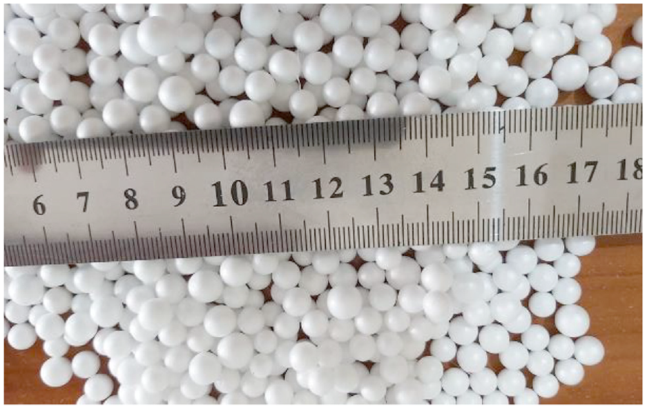
Expanded polystyrene used in this study.
Mix proportion
For all the mixes, the cement content was 450 kg/m3 with a water/cement ratio of 0.45, which was kept small for producing higher strength concrete, Mohd et al. 11 Mix design was carried out based on a targeted strength of 50 MPa. Through trail mixes, it was found that this ratio can give a cube compressive strength of 55 MPa. It is expected that EPS beads lead to a reduction in compressive strength and using this mix ratio was aimed to avoid compressive strength being reduced below 17 MPa in order to be used as structural concrete as indicated in BS 8110. 12 The batch details of the mixes were arranged as presented in Table 1.
Batch mix proportioning.

Several refs. 13–15 reported the influence of various EPS contents on concrete properties. It was revealed that up to 20% have motivating results or miner negative effect on fresh and hardened properties of concrete. In this study, EPS content increased up to 40% to study its structural performance. Five different mixtures (0%, 10%, 20%, 30% and 40%) were prepared with different EPS contents to examine its effect on concrete density, compressive strength and slab punching shear capacity properties. In the mixtures of EPS-10 to EPS-40, gravel content was partially replaced with 10%, 20%, 30% and 40% of EPS beads by volume. In general, these replacement ratios are equivalent to about (Cement: EPS; 1:0, 2:1, 1:1, 1:1.5, 1:2). The amounts of water, cement, and sand were kept constant for all mixes.
The interfacial zone between cement paste and aggregate plays a critical role in determining the mechanical properties of concrete, Husem. 16 For this reason and in order to produce a cohesive mix to restrain the EPS from floating on the surface of the concrete mixture, EPS beads were wetted initially with a part of the mixing water and cement slurry before adding the remaining materials and also to increase its weight and decreasing its tendency to float over the sand and gravel later inside the mixer. Six identical cubes (100 × 100 × 100) mm were casted for each mix to determine the density and compressive strength of concrete at the ages of 7 and 28 days according to BS-1881-Part 4.
Specimen preparation
The molds of slab panels were fabricated with inner dimensions of 500 × 500 × 50 mm. The columns’ molds were made to give two column sizes; 50 × 50 and 50 × 75 mm. A 10 mm layer of concrete was poured into the molds to ensure a 10 mm steel cover on the bottom, then the mesh was placed and cast the remains. After finishing slab casting, the molds of the columns were placed at the center of the panels and filled with concrete in three layers with rod compaction to ensure its monolothicality with the concrete beneath. At the end, the concrete surface was leveled using a steel trowel. For each patch, two slab panels were casted and then demolded with the cubes after 24 h, kept in water for 7 days, then cured in lab’s air up to the testing days, as shown in Figure 2.

Slab panels after curing period.
A total of 10 simply supported slab panels were constructed and tested under concentrated load, Table 2. The test parameters were EPS content, concrete strength, and column aspect ratio. The slabs were reinforced in two-way direction with a constant reinforcement ratio (
Geometrical details of slab panels.

1 for 50 × 50 mm column, aspect ratio β = 1.0, 2 for 50 × 75 mm column, β = 1.5, effective depth d = 38 mm.

Slab layout and details.
Test setup and instrumentation
The cubes were weighed and tested at 7 and 28 days, while all slabs were tested late at the age between 50 and 60 days. Slabs edges were simply supported on a square steel frame with a clear span of 450 mm, as shown in Figure 4. The slabs were fixed with special steel frames at the corners against the rotation. The slabs were loaded in a computerized INSTRON universal machine (Floor Model 5980 Testing System) with a capacity of 100 kN at the Faculty of Engineering’s laboratory of Koya University. The load was applied on the centered column using a rigid circular plate in a rate of 0.4 kN/s. The Load-central deflection responses were measured and recorded on the data acquisition system. It was observed that the column penetrated down into the slab at the ultimate load. As a result, all slabs failed in two-way shear.

Slab set up for the two-way shear test.
Experimental results and discussions
Concrete density
The dry densities of concrete containing EPS powder are lower than that of the control concrete. Table 3 presents the average densities of three specimens from all types of concrete mixes at 28 days. The results show a decrease in density with an increase in EPS content, it ranged from 2415 to 1810 kg/m3 at the gravel replacement levels from 0% (control) to 40%. The reductions percent for various mixes (EPS-10 to EPS-40) compared to control specimens also shown in Table 3 and Figure 5. The main reason for the decrease in the densities is that EPS beads have a lower specific gravity than the specific gravity of the replaced gravel.
Concrete density at the ages of 28 days.


Concrete density versus expanded polystyrene content.
Concrete strength
Compressive strength is the most vital mechanical property for hardened concrete. Table 4 and Figure 6 present the results of the compressive strength using CONTROL Compression Testing Machine 3000 kN. Figure 7 shows the percent drop in compressive strength with EPS contents at both 7 and 28 days. There is a significant reduction in the compressive strength as the amount of EPS increases compared to that of the control mixture for both ages. It can be noted that the reduction in compressive strength for both 7 and 28 days is almost the same. This similarity is attributed to the effect of no pozzolanic or micro-filling influence of EPS beads. The reductions in the compressive strengths of samples with EPS content of 10%, 20%, 30%, and 40% are nearly 40%, 60%, 66%, and 70%, respectively compared to the control mixture on average of both ages. Tests showed a slight increase in (28/7) days strength ratios when EPS content increased as shown in Figure 8, which may be related to the additional void space of EPS which gives more space to cement for hydrating with time in such a high cement content.
Cubic compressive strength at the ages of 7 and 28 days.

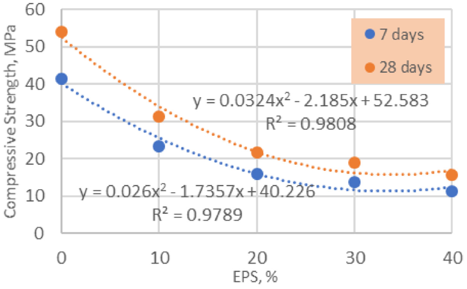
Compressive strength versus expanded polystyrene content.

Compressive strength drop after adding expanded polystyrene.

Ratio of (28/7) days versus expanded polystyrene content.
Failure mode of slab panels
The crack pattern on the tension face of each specimen is shown in Figure 9. Generally, there are two types of crack patterns in the failed specimens: shear cracks and a combined shear-flexural behavior. As the load increased, some radial cracks started to appear in some samples and extended in the shear perimeter towards the slab supports. At the same time, the cracks increased in number at the central region of the slab. At the peak load, the column experienced a sudden fall into the slabs. It was observed that there were no cracks in the compression side of the slabs, except the punching cracks around the loaded contact area at failure.

Slab bottom face after failure.
Experimental two way shear strength
Experimental details of the tested slabs are presented in Table 5. After the tests, area (AExp) of the failure zone for each specimen was measured using the AutoCAD software. The same procedure for measuring (AExp) was used in previous works.17–20 The area ranged between about 66k mm2 for EPS-00 to 115k mm2 for EPS-40 for 50 × 50 column, and ranged between about 69k mm2 for EPS-00 to 120k mm2 for EPS-40 for 50 × 75 column. It has been shown that the larger EPS content, the higher punching cone base area. The reason may be related to the debonding between the lower part at the mesh level with the upper part. The peak load was considered as a two-way shear failure (
Experimental and calculated details of panels’ test.

C.P denoted to critical punching perimeter. All panels with same reinf. Ratio = 0.661%, and d = 38 mm.
Effect of EPS on shear strength
Several material properties and geometric parameters govern the two-way shear capacity, including the compressive strength of concrete. 17 Figure 10 shows the average shear strength of the tested slabs corresponding to the percent of EPS content. The shear strengths is reduced with increasing EPS content compared to the slabs with the control mixture.

Experimental shear strength versus expanded polystyrene contents.
It has been proofed, as shown in Figure 11, that the drop in punching strength is less than the drop in the concrete strength, such that the drop in shear strength for 10%, 20%, 30% and 40% of EPS was 8.8%, 16.8%, 20.8% and 27.8% in average of both column types respectively, while the reductions in the compressive strengths was about 40%, 60%, 66%, and 70%, respectively as shown before.
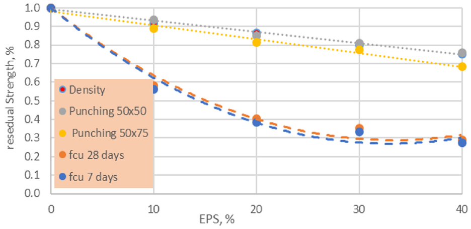
Comparison between concrete strength and shear strength drop versus expanded polystyrene contents.
Figure 11 above shows that the reduction in punching strength is nearly linear while the drop in the concrete strength was in a quadratic relation. In addition, it shows that the drop in the punching shear strength is similar to the drop in the concrete density; this means that punching shear strength is related to the concrete density rather than the concrete strength. It is worth to mention that the test results are conformed to the results by Yang et al., 8 they stated that the radius of the punching shear tended to increase with the decrease in the unit weight of concrete. This yielded a lower normalized punching shear capacity observed for all-lightweight aggregate concrete (ALWAC) and sand-lightweight aggregate concrete (SLWAC) than normal-weight concrete flat slabs. Figure 12 presents graphically some test results.

Graphical presentation for some results: (a) failure area versus compressive strength, (b) failure area versus EPS content, (c) critical path versus EPS content (Note; ACI code is at 0.5 d), and (d) failure angle versus EPS content.
It was reported by Osman et al. 21 and Youm et al. 22 that the failure angle of LWAC flat slabs was slightly lower than that of NWC slabs. Clarke and Birjandi 23 proofed that the aggregate type used have a major role in acheving the flat slabs peak load and the angle of failure surface and their values are the lowest for flat slabs made with an expanded clay aggregate concrete.
In this study, tests showed that the failure surface angles reduced with the increasing of the EPS content. This is due to the fact that the friction angle of LWAC is slightly higher than that of NWC and the effect of lightweight aggregate interlocking action is minimal (as stated by Osman et al. 2000 and Yang et al., 2016), resulting in the failure surface generatrixes having a low angle of failure surface.
Prediction of shear capacity by some international codes
Before examining the effect of EPS beads on two-way shear strength of concrete, it is useful to evaluate and compare the inherent punching strength of concrete as described in building codes and design standards, knowing that International codes and standards vary in their models for estimating punching shear capacity. 24 Alos, these comparison between the experimental results and the results computed according to the International codes equations is very important to provide the designers with detailed information about the conservations taken out by these codes equation used in the design of slabs.
The experimental and international standards’ prediction punching strength values are summarized in Table 6. The (Vexp/Vpre) ratios were calculated with ACI, BS, and EC-2.
Experimental and predicted code shear load capacity.

Shear load according to ACI 318-19M
Shear resistance without shear reinforcement can be calculated based on the clause 22.6 in ACI 318-19M. 25 The code considers the critical perimeter as a rectangular area around the column at the distance of (0.5 d) from the column face. As per ACI (2019 Table 19.2.4.1(a)) consider (λ) to account for the reduced shear capacity of lightweight concrete
Shear load according to BS 8110
The BS 8110 (1985) 12 adopts the same design parameters as that of normal weight concrete members with reducing the permissible shear stress reduced by 0.8 times the values for normal weight concrete if the grade of concrete is greater than 25 MPa under the condition that the maximum shear stress will not exceed 0.63 fcu or 4 MPa whichever is lower. The critical shear perimeter is taken as a rectangle at (1.5 d) from the column faces regardless of whether the column section is rectangle or circular.
Shear load according to Eurocode 2
Many studies work on comparing experimental loads with the internationals codes.8,17–20 The two-way shear for the slabs without shear reinforcement is computed according to Eurocode 2 (BS EN 1992-1-1:2004, clause 6.4). 26 According to Eurocode 2, the control perimeter is modeled as a rectangular geometry with a distance of (2.0 d) from the column periphery. As per EC-2, a reduction factor η (η = 0.40 + 0.6 (ρ/ρc0) where ρc0 is the reference value 2300 kg/m3) is considered to account for the shear capacity of lightweight concrete flat slab.
As shown in Figure 13, ACI, BS, and EC-2 underestimated the failure load for all tested slabs, but the ACI (2019) code underestimation increased with the increase of EPS content and hence the decrease in concrete density, indicating that the ratio of experiments to predictions (VEXP = VPre) was approximately 1.47 for the specimens with a concrete density of 2400 kg/m3 and approximately 2.21 for the specimens with a density of 1800 kg/m3 and the effect of the concrete strength was found to be minimal. Same behavior with EC-2 but with less intensity as pointed out by Yang et al., 8 Marzouk et al. 27 and Osman et al. 21

Ratio of Vpre/VExp versus expanded polystyrene contents.
Slabs deflection
During the test, all tested slabs exhibited almost similar deflection within the pre-cracking stage despite the different parameters investigated. This is due to the dominance of the gross concrete cross section properties. On the other hand and at failure stage, tests showed that when EPS content increased, the peak mid-span deflection increased also, as shown in Figure 14 which shows the deflection corresponding to failure load for all tested slabs. In addition, tests showed that the deflection of slabs with 50 × 50 mm columns is higher than the slabs with 50 × 75 mm columns; this is because the punching capacity is higher and this leads an increase in the ultimate load and deflection.

Peak deflection at failure versus expanded polystyrene contents.
Conclusion
This research has explored the characteristics of a new two-way lightweight concrete slab consisting of Expanded Polystyrene (EPS) as a gravel partial replacement. The mechanical properties have been discussed in order to study the behavior of EPS under different percentages of usage prior to study its effect on two-way flat slab punching behavior.
This work can be considered a new line of research for lightweight concrete as the mixing method is very simple, relatively inexpensive and does not need complex machinery systems of mixing or superplasticizer and bonding agents. The following conclusions may be drawn:
Partial replacement of normal weight coarse aggregate with Expanded Polystyrene aggregate changed the concrete properties, such as unit weight and compressive strength depending on the level of replacement.
The EPS beads have a closed cellular structure, increasing their volumetric proportion in the mixes decreases markedly the compressive strength.
All the EPS concrete without any special bonding agents show good workability and could be easily compacted and finished.
Tests sowed that each 10% replacing of gravel by EPS beads reduces the weight of the concrete by about 6.3%.
Tests showed that the compressive strength and its reduction ratio have a quadratic relation with increasing EPS content rather than a linear relation.
Slight increase in the ratio between 28 and 7 days with increasing EPS content with an average value around 1.355.
Ultimate punching strength for the 50 × 50 mm columns reduced about 6.0%, while for the 50 × 75 mm columns reduced about 7.9% for each 10% EPS added, with an average of about 7% for each 10% EPS added.
It was found that the angle of punching shear failure decreased with increasing EPS content. This reduced inclination gives an increase in the critical perimeter of the EPS concrete slab.
Tests showed that the drop in the punching shear strength is similar to the drop in the concrete density; this means that punching shear strength is more related to the concrete density rather than the concrete strength.
ACI 318-19, BS, and EC-2 underestimated the experiments of all flat slabs but with large intensity of ACI code with the increasing EPS content.
The fact that all codes calculations used in this study give low (Vpre/PExp) ratios indicates that the punching effect of lightweight concrete is less pronounced when compared with an ordinary flat slab.
Footnotes
Handling Editor: Chenhui Liang
Declaration of conflicting interests
The author declared no potential conflicts of interest with respect to the research, authorship, and/or publication of this article.
Funding
The author received no financial support for the research, authorship, and/or publication of this article.