
Abstract
As a power output unit, Induction Motor (IM) is widely used in Electric Vehicles (EV) due to its unique advantages of higher power density and better torque ability. With more complicated motor controller system, there are some hardware and software failures which bring some risks including EV unexpected acceleration or deceleration, therefore it is necessary to build high-accuracy torque estimation and safety control strategy. Firstly, hazard and safety concept are analyzed to make sure function safety goals and levels for IM system. Secondly, a novel method of high-accuracy torque estimation is proposed based on a rotor dynamic and composite flux linkage observer. Then, fault diagnosis and handling mechanisms of motor torque are designed to avoid hazards when it is a significant difference between motor estimation torque and vehicle requested torque. Finally, power test and Hardware in Loop (HIL) bench are configured to verify torque estimation accuracy and fault protection mechanisms rationality by comparing test results and injecting related faults. Experiment result shows that motor torque accuracy is within ±5 Nm and fault protection mechanisms can bring motor to safety state promptly.
Introduction
With increasing awareness of environment protection, most countries pay much attention to do research and develop new energy vehicles all over the world.1,2 Induction motor are widely applied as a front auxiliary four-drive EV because of its high efficiency at special operation point (such as high motor speed and low torque), low manufacturing cost, simple structure, and excellent control performance.3–5
Currently, high integration of motor drive system can improve energy density, optimize structure layout as well as cut down manufacturing cost of power components. But complicated motor system integration (such as software and hardware) brings some failure risks that generates unexpected acceleration or deceleration caused by abnormal motor torque. 6 Motor torque control accuracy is crucial to safe vehicle driving because the power distribution has a significant dependence on the torque accuracy. However, torque measurement devices are expensive, which would also increase size, reduce reliability by electromagnetic interference, and so on.7,8 Alternatively, torque can be estimated, but for special vehicles, due to the limitation of space and weight.
According to actual requirements above, a high-accuracy torque estimation and fault protection strategy should be comprehensively built. Nowadays, researchers put much focus on motor torque estimation as below. With the development of intelligent algorithm, some scholars try to apply neural network to torque estimation. Liu et al. 9 presents a torque estimation scheme for induction motors based on gated recurrent unit and uses recurrent neural network structure to learn the relationship between the excitation and response sequences of the motor. Vishwakarma et al. 10 proposes a 1D convolutional neural network for motor torque prediction model and gets this model based on motor data. Du et al. 11 proposes a model integration algorithm to optimally fit the nonlinear relationship among electromagnetic torque, motor current, and angle. The algorithm contains the strong coupling ability of BP neural network and the stability of mathematical model. Other scholars also build flux linkage observer to obtain motor estimation torque. Bahloul et al. 12 adopts fast adaptive Luenberger observer approach to ensure the asymptotic convergence of the flux and the load torque estimation errors. Additionally, Baccarini et al. 13 proposes a non-intrusive method for in-service torque estimation of induction motors is reported. The technique is based on the root mean square value of signals which are usually found on the machine control panel (current, voltage, and power). Kousalya et al. 14 presents a sliding model-based predictive torque control of an induction motor for the electric vehicle application. The presented control scheme offers a nonlinear switching feedback term in the prediction equation to overcome the model uncertainties, disturbances, and variation in motor parameters. Nair et al. 15 presents extended Kalman filter algorithms without the aid of any feedback information, the potential of extended Kalman filter to follow exactly the changes in the load torque is utilized here and extended Kalman filter based on senseless drive is proposed for the torque estimation in direct torque-controlled motor. Yamamoto et al. 16 presents a high-precision torque estimation method of a variable speed induction motor without related sensors and accurately estimates the torque considering the variation of the stray load loss due to the changes of the main flux level and rotational speed.
In order to accurately estimate torque at no additional cost without influencing IM system, this paper aims to estimate IM torque by calculating rotor flux at different motor speed range. Firstly, functional safety concept is developed to identify risks and ensure safety level for IM. Then, flux linkage of α and β axes is calculated based on voltage and current flux linkage equations respectively and total flux linkage for IM rotor is obtained by combining flux linkage of α and β axes at different IM speed range. Next, IM torque estimation model is proposed based on final flux linkage and torque fault protection mechanism is built to avoid unexpected acceleration and deceleration. Finally, IM torque estimation is compared with actual measurement torque and torque fault protection mechanism is also verified by injecting fault torque. Test results show that the proposed safety control strategy performs well based on high accuracy torque estimation when IM torque faults occurs.
Functional safety concept design
Function recognition and application scenario
Due to complicated functionality integration for IM, system random failure risks caused by software and hardware continue to increase. 17 Therefore, safety mechanisms and treatment measurements are designed to avoid harm during vehicle driving. On this stage, vehicle functions and operation scenarios are identified. The function identification of Induction Motor Controller Unit (IMCU) is divided into three types such as providing drive torque, regeneration brake torque, and zero torque. When receiving driving request from the Vehicle Controller Unit (VCU), IMCU outputs driving torque to propel the vehicle forward or reverse. When receiving braking request from VCU, IMCU outputs regeneration braking torque to decelerate vehicle. When receiving stop mode from VCU, IMCU prohibits output torque so that the vehicle comes into the parking scenario.
Hazard analysis and risk assessment
After IM function identification and operation scenario are determined, exposure probability (E), controllability (C), and severity (S) are carried out to analyze possible hazards from vehicle actual scenario and determine Automotive Safety Integrity Levels 18 (ASIL, four levels from ASIL A to ASIL D). E is divided into five grades which increases from E0 to E4, C is also divided into four grades which decreases from C0 to C3, and S is divided into four grades which increases from S0 to S3. Considering complicated road condition and usage scenario, IM ASIL is determined by combining three parameters of E, C, and S as a reference shown in Table 1. The safety level is designated ASIL C due to hazards analysis and risk assessment caused by torque failure in vehicle operation scenario.
The table of hazard analysis and risk assessment for IM.

Torque monitor framework design
According to above hazard analysis and risk assessment for IM operation scenario, it is necessary to build torque monitor and safety control scheme. Currently, three-layer torque monitor framework is usually used based on standardized EGAS monitoring concept. 19 According to ISO 26262 requirements20,21 and actual project development experience, IMCU must effectively enter into safe state within Fault Tolerance Time Interval (FTTI) when IM output torque is abnormal.22,23 Therefore, a hierarchical three-layer torque monitor framework is proposed as shown in Figure 1. The input layer functionality is mainly responsible for transferring requirement torque and operation mode from VCU to the torque monitoring layer by end-to-end verification. The torque monitor layer realizes IM torque estimation, monitor, and safety control action. IMCU outputs PWM signal to control IM operation at normal operation state. Additionally, IMCU outputs cut-off signal to inhibit IM torque release when torque faults, hardware faults, and IMCU faults occur. The output layer performs IGBT drive control at normal state and put IM into freewheeling safety state when correlated faults originates from torque monitor layer.

Torque safety monitoring framework.
IM torque estimation
This section presents the proposed torque estimation method based on a dynamic and composite flux linkage observer at different IM speed range. Figure 2 shows the flowchart of torque estimation approach proposed in this paper. On the one hand, voltage and current rotor flux linkage model of α and β axes are built respectively. On the other hand, the model of rotor total flux linkage is created by combining rotor flux linkage of α and β axes with IM speed coefficient to estimate IM torque.

The flowchart of torque estimation approach.
Rotor flux linkage for voltage model
Three-phase volts and currents for IM stator are used to build rotor flux linkage


Where

Where

Where
Rotor flux linkage for current model
Three-phase currents for IM stator are used to build rotor flux linkage


Where
Rotor total flux linkage and IM torque model
According to rotor flux linkage for voltage and current model, rotor flux linkage model for α/β axes is proposed to decide application and transition between above two models as equations (7) and (8).


Where
IM speed switch point

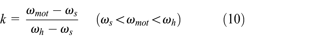
Where
Therefore, rotor total flux linkage

According to rotor total flux linkage

Where
Additionally, IM torque direction for a task period is defined by motor input power, copper loss as well as IM speed from equation (13).

Where
IM torque fault diagnostic and handling mechanism
Torque fault diagnostic and handling mechanism are necessarily built to ensure output torque safety. IM high-accuracy estimation torque from equation (12) is compared with VCU required torque and IM output torque is prohibited when torque faults occur according to Figure 1. Excessive torque deviation and opposite torque direction are mainly considered as two torque faults. Meanwhile, related diagnostic and handling mechanism are respectively laid down as below.
Excessive torque deviation diagnosis and handling
Excessive torque deviation fault between VCU required torque and IM estimation torque is judged by equation (14) and torque deviation is out of safety area in Figure 3. 27 IM torque fault handling mechanism is actually applied if equation (14) meets condition, IM controller cuts off output torque to zero within Fault Tolerant Time Interval (FTTI, ΔTFTTI ≤ 150 ms).

Where

Torque deviation fault check scheme.
The definition of sign factor

Opposite torque direction diagnosis and handling
In order to check whether estimation actual torque direction is opposite to VCU requested torque direction or not and estimation torque direction is calculated based on equation (13) (non-negative value means torque positive direction, otherwise means torque negative direction). As shown in Figure 4, IM actual estimation torque (positive direction) is reverse with VCU requested torque direction and IM actual estimation torque absolute value
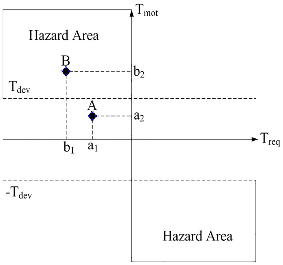
Torque direction fault check scheme.
Experiment validation
IM torque estimation accuracy and fault handling mechanism are necessarily verified by building testing environment. On the one hand, powertrain test bench is used to compare IM estimation torque with actual test torque by sensor. On the other hand, Hardware in Loop (HIL) test bench is applied to check the rationality of faults diagnosis and handling mechanism.
IM torque estimation accuracy validation
The power experiment platform is shown in Figure 5. IM operates under all load condition with proper cooling and a high accuracy torque sensor is installed to obtain IM actual torque. The experimental information is observed and stored in real-time by using high-speed logger, experimental data are exported and plotted by PC software at the same time. The HIL test bench is shown in Figure 6. DSPACE and its control interface are considered as VCU to send motor control parameters (such as requested torque and IM operation mode) to IMCU hardware by CAN bus. Actual estimation torque can be modified to simulate fault injection by IMCU control interface and communication unit.
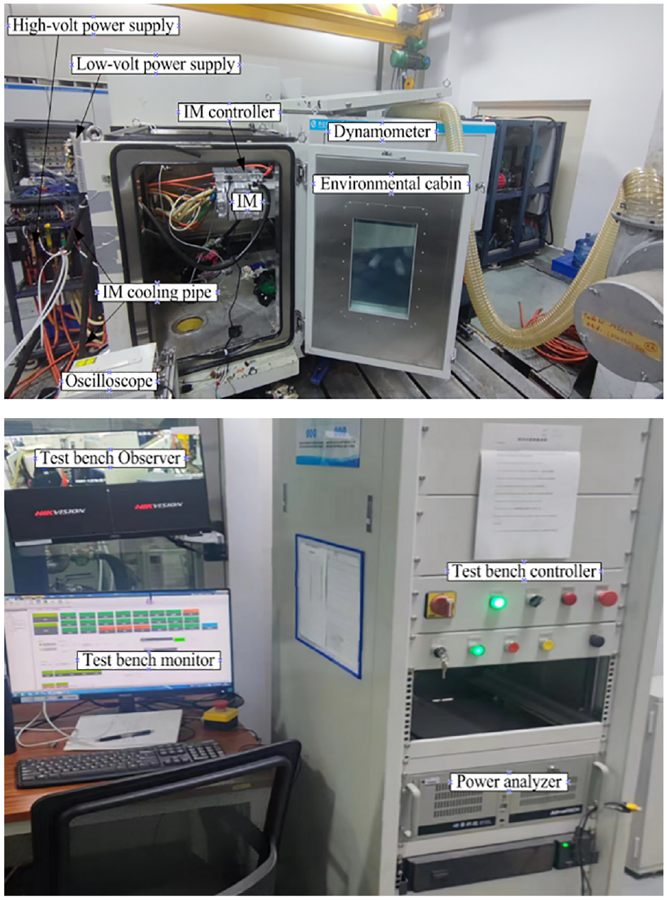
Powertrain experiment platform.

HIL experiment platform.
Validation results of IM torque estimation accuracy is shown in Figure 7. According to comparison results, the error between estimation torque and actual test torque is within ±5 Nm on whole operation condition. Therefore, estimation torque accuracy meets requirement of torque monitoring and fault handling, IM estimation torque method proposed in this paper can be used as an alternate torque value to actual test torque by sensor.

The results of torque accuracy comparison.
Validation for IM excessive torque deviation
Based on fault diagnosis and handling mechanism of excessive torque deviation in section “Excessive torque deviation diagnosis and handling,” positive and negative torque deviation faults are injected by using IMCU control interface to modify estimation actual torque. According to validation results of IM driving status (3000 rpm and 10 Nm) in Figure 8, IM system goes from normal operation state (state flag = 1) to safe state (state flag = 5) and actual torque is cut down to zero within 82 ms (ΔT ≤ 150 ms) when absolute torque deviation exceeds torque threshold limit (initial calibration value = 50 Nm). Similarly, validation results of IM power generation state (1500 rpm and −10 Nm) in Figure 9, IM system also comes into safety state and actual torque drops to zero within 108 ms (ΔT ≤ 150 ms) when absolute torque deviation is out range of torque threshold limit.

Validation of torque deviation fault at 3000 rpm/10 Nm.

Validation of torque deviation fault at 1500 rpm/−10 Nm.
Validation for IM opposite torque direction
Based on fault diagnosis and handling mechanism of excessive torque deviation in section “Opposite torque direction diagnosis and handling,” positive and negative torque opposite-fault is injected by using IMCU control interface to modify estimation actual torque. According to validation results of IM operation status (2000 rpm and 55 Nm) in Figure 10, IM system goes from normal operation state (state flag = 1) to safe state (state flag = 5) and actual torque is cut down to zero within 62 ms (ΔT ≤ 150 ms) when actual estimation torque direction is reverse to that of requested torque and its absolute value exceeds torque threshold limit (initial calibration value = 50 Nm). Meanwhile validation results of IM operation status (2000rpm and –10Nm) in Figure 11 show that IM system goes from normal operation state (state flag = 1) to safe state (state flag = 5) and actual torque is cut down to zero within 61 ms (ΔT ≤ 150 ms) when torque reverse fault occurs.

Validation of torque reverse fault at 2000 rpm/55 Nm.

Validation of torque reverse fault at 2000rpm/–10Nm.
Conclusion
Torque estimation accuracy plays an important role especially in power motor safety control. Torque faults which bring unexpected acceleration or deceleration for EV is also be eliminated by proper fault diagnostic and handling mechanism. However, the nonlinear relationship between torque and current is more prominent due to IM physical property. IM torque estimation accuracy often cannot meet requirements by using conventional torque estimation method. Therefore, high-accuracy torque estimation method and safety control strategy are designed as below steps in this paper.
(1) Hazard analysis and risk assessment are defined based on IM function recognition and application scenario. Then IM ASIL and safety goals are determined by analyzing and considering exposure probability (E), controllability (C), and severity (S) comprehensively.
(2) To overcome the defect of conventional torque estimation method, three-layer torque monitor framework is built and a novel torque estimation method which combines voltage with current flux model is proposed to create a dynamic and composite flux observer closely related to IM speed zone.
(3) IM torque fault diagnosis strategy is used to check two types of faults such as excessive torque deviation and opposite torque direction when actual estimation torque and VCU requested torque are compared. Meanwhile, torque fault handling mechanism prohibits IM output torque within FTTI when torque faults occur based on test results.
(4) To check torque estimation accuracy, actual estimation torque proposed in this paper is compared with that of actual test results in power experiment platform, comparison results show that torque estimation accuracy meets requirement of torque fault diagnosis. Finally, the rationality of torque fault diagnosis and handling mechanism is verified by injecting fault torque in HIL test bench.
Footnotes
Acknowledgements
The authors would like to thank the reviewers for their corrections and helpful suggestions.
Handling Editor: Chenhui Liang
Declaration of conflicting interests
The author(s) declared no potential conflicts of interest with respect to the research, authorship, and/or publication of this article.
Funding
The author(s) disclosed receipt of the following financial support for the research, authorship, and/or publication of this article: This work was supported by PEF20A electric drive all in one system development project (Grant No. SN200301).