
Abstract
Motor as well as its controller plays an important role in driving electric vehicle. As sole power device, it is closely related with actual torque accuracy to make sure security during EV driving. Due to complex controlling system for motor, there are some random failures of hardware and software which can bring a series of unexpected risks for EV acceleration or deceleration. A novel method based on motor parameters feature is proposed to estimate motor torque based on parameters feature extraction for three-phase of volts and currents. Additionally, Quality Factor (
Introduction
With increasing awareness of energy conservation and environmental protection all over the world, government and automobile enterprises put much focus on electric vehicle.1–4 Permanent Magnet Synchronous Motor (PMSM) is widely used in electric vehicle due to its wide range of higher efficiency and higher power density.5–8 Currently, high efficiency and power density is used with integration improvement for motor system. Meanwhile, system failure risk is gradually produced due to deeper integration complexity. Motor system failures bring a series of hazards to pedestrians or passengers, additionally great business profits and brand losses which are caused by motor system failure enforce automobile enterprises to take effective measurement and put motor function security all over the world. 9
Abnormal torque output to drive electric vehicle is main part for motor system failures. Torque failure which brings electric vehicle to unexpected acceleration or deceleration state includes unacceptable torque and torque opposite direction failures chiefly. Therefore, it is very important to estimate motor actual torque accurately and cut off torque output to make sure no generation of unexpected acceleration or deceleration within proper time when motor system comes into software or hardware failures during electric vehicle running. 10
Obviously, it is significant to build a method and architecture scheme to estimate motor actual torque precisely, then the protection strategy of motor torque security should be designed to ensure vehicle from hazard state to security state when motor torque comes into serious failure state. Therefore, researches on actual torque estimation and torque security control are concerned among automobile enterprises and scientific research units.
Zhao 11 designs a security monitoring model of torque control strategy for pure electric vehicles and security analysis methods based on international standard ISO 26262, and the design of security mechanism ensures the system into safe state when failures were checked. Wu et al. 12 introduces basic method of Hazard Analysis and Risk Assessment (HARA) related with functional security standard, then security goal and Automotive Security Integration Level (ASIL) of Motor Control Unit (MCU) have been derived according to HARA and the implementation of function monitoring level was proposed by analysis of function security architecture. Song 13 studies the fault modeling of MCU by carrying out fault tree analysis, then the software architecture of motor function security is designed based on the idea of layering and modularization. Sabbella and Arunachalam 14 develops the functional security and technical security concept of related functions such as torque monitoring, Additionally, he also designs technical security requirements and the functional security concept by using three-level security monitoring architecture.
According to previous summary, there are common analysis and development process based on ISO 26262 all over the world. The accuracy of classic torque estimation based on current method of d and q axis coordinate is easily affected by other inherent parameters such as inductance of d and q axis coordinate as well as motor flux linkage. Meanwhile, these parameters which is adopted to estimate torque may cause invalid fault torque if there is no consideration of confidence coefficient for each parameter. Therefore, parameters feature extraction for three-phase of volts and currents as well as confidence coefficient and QF are used to develop algorithm to monitor motor actual torque accurately and ensure motor system safety.
The process of function security development
Due to increasing with new function development and integration complexity, software and hardware may cause greater risks of random system faults. 15 Therefore, a series of effective security methods and protection measurements should be applied to avoid serious hazard based on ISO 26262 development process.10,16 Firstly, risks and hazards related with main driving functions for power system should be analyzed and identified according to Figure 1. Then, function security requirement and function security goal are figured out by analyzing levels of exposure (E), severity (S) as well as controllability (C), next technical security requirements are decomposed into hardware and software requirements based on the determination of security goal. Lastly, a novel algorithm of torque estimation is proposed in the phase of software security requirement determination based on parameters feature extraction for three-phase of volts and currents.

The process of function security development.
The concept design of motor torque security
Firstly, the aim of concept design is to ensure function items and usage scenario of electric vehicle. Then failure risks are analyzed. Finally, security goals and solution measurements are worked out for each risk. 17
Usage scenario analysis for function item
There are three main function items including propulsion, braking, and parking based on requirements from vehicle to motor. For propulsion and braking function items, when motor system receives requirement torque and operation mode from Vehicle Control Unit (VCU), electric vehicle may run forward or backward direction at different road states such as icy road, wet, slippery pavement as well as dry pavement, and so on. For parking function items, when MCU receives “Zero” torque and power-down mode from VCU, electric vehicle comes into state of stationary.
Hazard analysis and risk assessment (HARA)
When hazard function happens due to software and hardware failures, it is necessary to consider and finish hazard analysis as well as risk assessment in Table 1 and take a series of effective measurements to eliminate unreasonable torque execution which will suddenly bring unexpected acceleration or deceleration. 18
The table of hazard analysis and risk assessment for motor system.
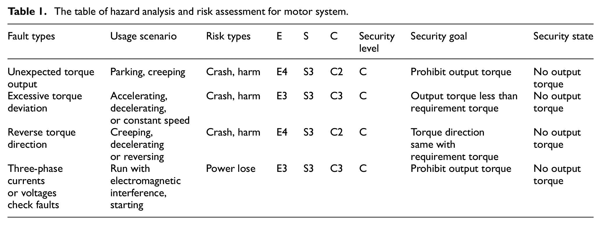
After usage scenario is confirmed, function security levels for motor system are defined as four layers from ASIL A to ASIL D by setting indicator parameters E, S, and C of function risks which comes from actual usage scenario for electric vehicle.19,20 E includes five layers from E0 to E4 increasing with hazard exposure probability level. S includes four layers from S0 to S3 increasing with hazard severity level. C includes four layers from C0 to C3 decreasing with hazard controllability level. Function security level and goal are evaluated and confirmed by combining actual usage scenario and road situation with hazard occurrence of E, S, and C. 21
The design of motor torque estimation and security control
The normality of motor torque operation plays an important role for electric vehicle security based on HARA analysis. Therefore, it is vital to design reasonable and effective architecture scheme of motor torque estimation. Here, three-layer architecture scheme of torque estimation is designed including input level, control level, and output layer in Figure 2.
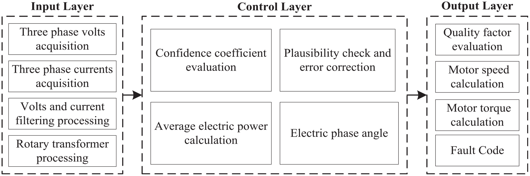
The architecture scheme of torque monitoring.
Input signal process
In input layer, three-phase volts and currents are obtained with filtering process as important parameters for motor torque estimation. 22 Additionally, the signal of rotary transformer angle is used as a redundancy design to calculate motor speed when three-phase volts and currents go to be fault.
Confidence flag evaluation
In order to obtain reliable calculation parameters, it is necessary to check the confidence flag for three-phase volts and currents before they are used to estimate motor torque. Here, three-phase volts and currents are transformed into constant amplitude volts (

Where
Then, the sum of squares for constant amplitude volts (
Therefore, confidence flag of volts (
(1)
(2)
Where
Plausibility check and deviation correction
Kirchhoff law for three-phase volts and currents is used to judge whether “Null Shift” which affects

Where
If the sum of three-phase volts and currents don’t exceed to the limit value, deviation correction of volts and currents for each phase is just need as equation (3).

Where
Additionally, plausibility check in equation (3) is also adopted to consider

Where
Motor speed calculation and average power
Motor mechanical speed is obtained based on constant amplitude volts (
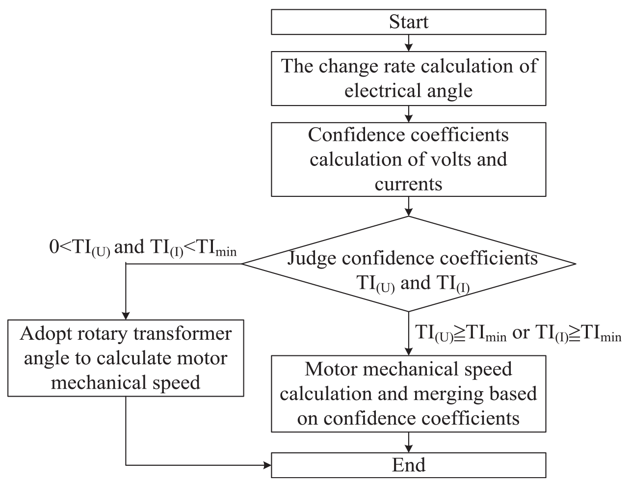
The calculation process of motor mechanical speed.
First of all, the change rate of electrical angle during a sample time interval

Where
Then, confidence coefficient of parameters for volts and currents are calculated in equation (6). Here, the sum of

Where
The calculation of motor mechanical speed depends

Where
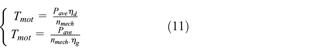
On the other hand, average power

Torque estimation and determination
In order to ensure the validity of torque estimation, quality factor

There are three states for
When
When


The relationship of motor currents and actual torque.
Where
When
Where
Failures diagnosis and security protection strategy
Driver requirement torque combined with power operation state from VCU analysis is send to MCU. The requirement of power and economy can be met by reasonable torque control, but abnormal motor driving or braking forces caused by incorrect torque estimation and invalid operation command generates unexpected acceleration or deceleration of EV. Therefore, reasonable fault diagnosis strategy and security protection mechanism are designed to ensure persons and motor system into security state before hazards and risks occur.23,24
According to previous description, the failures diagnosis judgment is decided for overrange faults parameters (such as three-phase volts and currents), significant torque deviation, torque direction fault as well as security protection strategy is designed respectively for each failure.
The solution scheme to overrange fault
When overrange faults for three-phase volts or currents occur, Kirchhoff’s law can’t meet requirements. Invalid parameters feature extraction brings serious hazards for powertrain torque control. So it is necessary to ensure motor driving system comes into security state by controlling low-side or high-side active short circuit for three-phase full bridge circuit. Meanwhile
The solution scheme to significant torque deviation
Significant torque deviation generates unexpected acceleration or deceleration behavior that brings drivers to serious hazards. Torque deviation range is decided carefully and set reasonably to void unnecessary power shut-off within normal range of torque deviation between motor output torque and VCU requirement torque. The torque deviation exceeding torque limit is considered as a judgment condition of serious torque deviation and active security state within Fault Tolerant Time Interval (FTTI,

Where
The definition of factor

The solution scheme to torque direction fault
In order to check torque direction fault, reasonable judgment condition is designed as equation (13). There are three steps as below:
Step (1): Confidence coefficient should be enough high (
Step (2): Estimation torque direction is obtained by equation (10) and compared with that of VCU requirement torque.
Step (3): When both directions are reverse, security state is active or inactive by judging which is greater between motor torque estimation
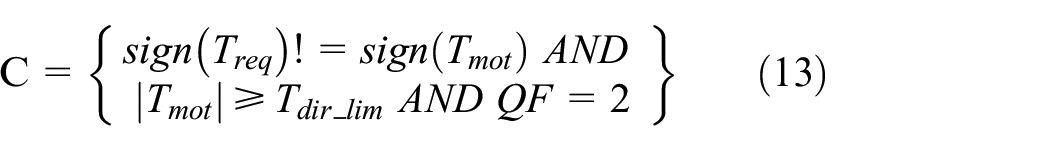
Where
According to Figure 5, When motor runs at point A, the direction of torque estimation (

Torque direction monitoring scheme.
Bench test
The model of torque estimation and security control is designed by the environment of MATLAB/Simulink, meanwhile source code is generated and complied by tools of Targetlink and CodeWarrior to hardware. Power and Hardware in Loop (HIL) test bench are built to verify torque estimation accuracy and security control strategy in Figure 6. VCU requirement torques and motor operation mode are sent to MCU by simulator dspace, feedback signals related with toque estimation and security control are observed by upper computer as a close-loop monitoring.

Power and HIL test bench.
Accuracy verification of estimation torque
It is necessary to check the accuracy of estimation torque before the rationality of security control strategy is verified. Therefore, estimation torque is compared with actual test torque within whole motor operation range. Power level test results show that estimation torque error is within ±5 Nm according to Figure 7 and estimation torque proposed in this paper can be considered as actual torque to be applied in torque security control.

The error between estimation and actual test torque.
Security verification of overrange fault
In order to verify security mechanism of overrange faults, V-phase volts and currents are brought to be overrange by calibration modification respectively. According to Figure 8, when V-phase volts exceeds upper threshold value (

Overrange volts verification of V-phase.

Overrange currents verification of V-phase.
Security verification of significant torque deviation fault
The security control strategy of positive and negative Torque Deviation Fault (TDF) is verified respectively at operation point (2500 rpm/+20 Nm, 1500 rpm/−20 Nm). Motor runs at operation state 2500 rpm/+10 Nm, when torque deviation between VCU requirement torque and estimation torque exceeds limit value (

Torque deviation verification at 2500 rpm/+10 Nm.

Torque deviation verification at 1500 rpm/−10 Nm.
Security verification of torque reverse direction fault
The security control strategy of positive and negative Torque Reverse Deviation Fault (TRDF) is verified respectively at operation point (4000 rpm/+55 Nm, 3000 rpm/−10 Nm). When torque direction between VCU requirement torque and estimation torque is reverse at motor operation state 1500 rpm/−10 Nm, and estimation torque exceeds positive torque limit (

Torque direction verification at 1500 rpm/−10 Nm.

Torque direction verification at 1500 rpm/−10 Nm.
Conclusions
According to the importance introduction of motor functionality security design for business profits, brand affect, and ISO 26262 standard requirements, the development process of motor function security is designed and work item for each step is defined. Functionality security level and security goal are ensured after EV usage scenario and powertrain system HARA are analyzed sufficiently.
Three-tier architecture scheme of torque monitoring is designed. Assuming parameter confidence coefficient is considered, feature extraction for three-phase volts and currents is adopted to calculate motor mechanical speed and average power after signal plausibility check and deviation correction is finished. In addition, estimation scheme of motor torque is also decided by confidence coefficient and QF level.
Check condition and handling mechanism of each fault are defined. Power and HIL test bench are built to verify the accuracy of motor estimation torque and validity of security control strategy. Test results show that the accuracy of motor estimation torque is within ±5 Nm and it can support the control strategy development of motor functionality security. For overrange fault, significant torque deviation fault as well as torque direction fault, security responding mechanism can bring motor torque to cut off within FTTI and ensure the security of EV driving.
Footnotes
Handling Editor: Chenhui Liang
Authors’ note
PENG Zhiyuan, DU Changhong and ZHOU Anjian design the method of motor torque estimation and security control strategy. LIU Li and CHEN Yang integrate and test software after software building. CHEN Jian and PENG Qianlei verify software validity by building test bench. The information above is confirmed.
Declaration of conflicting interests
The author(s) declared no potential conflicts of interest with respect to the research, authorship, and/or publication of this article.
Funding
The author(s) disclosed receipt of the following financial support for the research, authorship, and/or publication of this article: This work was supported by the Changan Multicomponent Integration of Electric Drive System (Grant No. 67612-53010210-030128), the Science and Technology Research Key Program of Chongqing Municipal Education Commission (Grant No. KJZD-K202000701), Key Projects of Technological Innovation and Application Development of Chongqing (Grant No. cstc2019jscx-fxydX0028), the Project of Green Aviation Technology Research Institute of Chongqing Jiaotong University (Grant No. GATRI2020 D02002).
Data availability statement
Data and materials in this paper can be available by other authors