
Abstract
In general, gearbox is prone to occur compound fault due to its harsh working environment and its fault vibration signal contains multi-components which correspond to each gearbox parts. As the multi-components are often coupled with each other and accompanied by strong noise which brings great difficulties to diagnose fault, however, the existing diagnosis methods are mainly applied on single fault rather than the entire gearbox health maintenance, therefore, this paper presents a gearbox compound fault diagnosis method and develops a diagnosis system which has potential value for gearbox health maintenance. In specific, on account of the morphological difference between multi-components, this paper uses resonance sparse signal decomposition (RSSD) to decompose the fault vibration signal into high and low resonance components respectively for achieving gearbox compound fault separation. Furthermore, as for low resonance component containing rolling bearing fault information, a weak fault feature extraction algorithm based on singular value decomposition (SVD) and cepstrum pre-whitening stochastic resonance is proposed, besides, aiming at the high resonance component containing gear fault information, an early gear fault warning algorithm based on local mean decomposition and two-dimensional approximate entropy of chaotic oscillator is also given. Finally, a gearbox fault diagnosis system, which has the ability such as the gearbox vibration signal acquisition, fault indicator warning, health status evaluation, fault signal storage is developed. Simulation validation and comparison prove the effectiveness of proposed method in this paper.
Keywords
Introduction
Gearbox generally acting as an important power transmission structure in rotating machinery results in the failure of entire rotating machinery system 1 due to complex working environment. In actual, as the gearbox contains gear, rolling bearing and shaft, and so on, its corresponding fault vibration signal often presents polymorphic property. For example, the rolling bearing fault shows transient impact appearance, gear fault reflects side frequency modulation phenomenon related to the shaft speed. 2 As a result, a series of gearbox compound fault detection methods have been developed such as priori guided matching filtering 3 and data-driven intelligent learning. 4 However, under the entire gearbox health maintenance condition, developing a gearbox compound fault detection method has significantly value.
In general, the prior guided matching filter is based on the feature extraction technology. Firstly, the dynamic fault response of gearbox is derived through the fault mechanism, and then the feature information reflecting the fault state is obtained from the fault vibration signal, so as to identify and confirm the compound fault.5,6 Generally, wavelet transform, 7 time-frequency representation technology, 8 adaptive decomposition technology3,9 and its derivative algorithm,1,6 improved envelope spectrum algorithm, 4 Kurtosis technique, 10 sparse model optimization characterization,11,12 and other techniques are often applied to extract weak feature information which also provides the basis for subsequent fault mode classification, health monitoring, reliability evaluation, and life prediction. On the other hand, data-driven intelligent diagnosis technology 13 is a new developed subject in recent years. Its advantage is that it integrates the expert experience in many fields, improves the diagnostic accuracy 14 which possesses the engineering advantage. 12 In recent years, artificial intelligence diagnosis technology15,16 has developed vigorously, such as support vector machine7,15 and deep learning.13,17 Besides, higher-order statistics18,19 is a powerful tool for gearbox fault diagnosis.
However, the classical gearbox fault diagnosis methods still have the following problems. Firstly, the lack of multi-component fault vibration signal separation which can diagnose compound fault. Secondly, the deficiency of weak fault identification on the key components of gearbox. For example, periodic transients in fault vibration signal which discriminate incipient rolling bearing fault are often disturbed by noise and require enhancement. Nevertheless, the sideband of modulation component in fault vibration signal reflects the gear’s deterioration degree and by monitoring its energy quantitatively, it achieves early fault warning. Finally, the existing diagnosis system in the market has no ability to evaluate gearbox health status with a reasonable cost.
In summary, this paper proposes a novel gearbox compound fault diagnosis method and develops a diagnostic system. Firstly, it separates fault vibration signal into multi-components, Furthermore, by processing multi-components, it achieve the rolling bearing weak fault enhancement and gear early fault warning respectively. Finally, experiment proves the feasibility of proposed method and combination Labview and Matlab, this paper develops a gearbox compound fault diagnosis system.
Gearbox compound fault diagnosis method
Diagnosis principle
When rolling bearing and gear occur fault in gearbox, its fault vibration signal often presents center frequency overlap phenomenon, 20 when using classical diagnosis algorithm decomposes fault signal, it will obtain irrelevant signal components, thus affecting the correctness of fault diagnosis result.
In order to solve this problem, considering the fault vibration signal presents morphological multi-component property, this paper decouples fault vibration signal, diagnoses rolling bearing weak fault, achieves early gear fault warning as shown in Figure 1.

Flowchart of gearbox complex fault diagnosis.
Gearbox fault vibration signal decomposition based on resonance sparse signal decomposition (RSSD)
In actual working condition, the gearbox vibration signal often presents multi-component property, such as periodic impacts, frequency doubling modulation, and so on. Although sparse decomposition has been extensively applied on detecting rotating machinery fault, the classical sparse decomposition method lack signal fidelity ability, it is not proper to directly detect gearbox compound weak fault consequently. As a result, this paper uses the RSSD which has significant advantage on penalty function and over-complete dictionary 21 to propose a gearbox multi-component fault vibration signal separation method.
Assuming that the gearbox fault vibration signal symbolizes X, in order to automatically match the periodic transients XL and the harmonic modulation component XH respectively that presents variously oscillating morphologies, RSSD uses Tunable-Q Wavelet Transform (TQWT) to construct the basis functions S1 and S2 with low quality factor and high quality factor respectively. On this basis, with the help of morphological component analysis (MCA), by constructing the penalty function of L1 norm, as shown in formula (1), the sparse representation of the two signal components XL and XH is realized, W1 and W2 represent the transformation coefficients of signal components XL and XH under the basis functions S1 and S2, respectively, λ1 and λ2 are regularization parameters. Finally, by using split augmented lagrangian shrinkage algorithm (SALSA) to compute iteratively formula (1), and achieve the minimum value of objective function J so as to obtain the estimated values


Weak rolling bearing fault enhancement based on SVD and CEP-SR
In general, although the extracted periodic transients
Step 1: According to the phase-space reconstruction theory, the extracted periodic transients

Furthermore, the Hankel matrix H is organized in the form of
Step 2: This paper performs SVD on matrix H as shown in formula (4). U represents a

Step 3: In order to reduce the noise, this paper uses the difference value between adjacent singular value
Step 4: Furthermore, the proposed method gets the real reciprocal spectrum C as shown in formula (5). By using the real reciprocal spectrum C, a whitening signal

Step 5: Finally, the SR is introduced to process the whitening signal

Early gear fault warning based on chaotic oscillators and two-dimensional approximate entropy
In general, the high resonance component XHE which corresponds to gear vibration often presents modulation property. However, when the gear occurs early fault, the amplitude of its side frequency band tends to increase. As a result, the key for incipient gear fault warning is to dynamically monitor the energy varying law of side frequency band. In order to solve this problem, firstly, local mean decomposition (LMD) decomposes the high resonance component XHE into a series of product functions (PF). Furthermore, by observing corresponding spectrum, some considerable PF components with obvious fault information construct a new signal XHE_RC, and the duffing chaotic oscillators are used to monitor whether the reconstructed signal XHE_RC has a side frequency band by observing its phase plane trajectory diagram. Finally, in order to identify the energy varying law of side frequency band and realize the gear early fault warning, a two-dimensional approximate entropy is used to quantitatively measure the confusion degree of trajectory map in phase plane. The specific process is shown as follows.
Step 1: Firstly, it decomposed signal XHE into a series of PF components as shown in formula (7). Furthermore, a reconstruction signal XHE_RC is obtained by combining the PF components whose spectrum exhibits side frequency band modulation property.

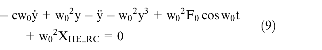
Step 2: Furthermore, it uses Holmes-type duffing oscillator to identify the chaotic state of phase plane trajectory map corresponding to signal XHE_RC and its initial equation is shown in formula (8). In the formula, c symbolizes damping coefficient,

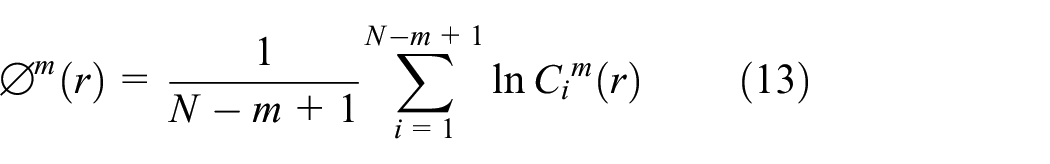
Step 3: Considering two-dimensional approximate entropy AE2d can describe the irregularity and complexity of phase plane trajectory, it can be used to achieve incipient gear fault warning quantitatively. In specific, it gives the entropy’s threshold value At and sets the embedding dimension


Validation
In this paper, the fault vibration signal

As for periodic transients

Bearing parameter table.

As for side frequency modulation component


As for the harmonic component

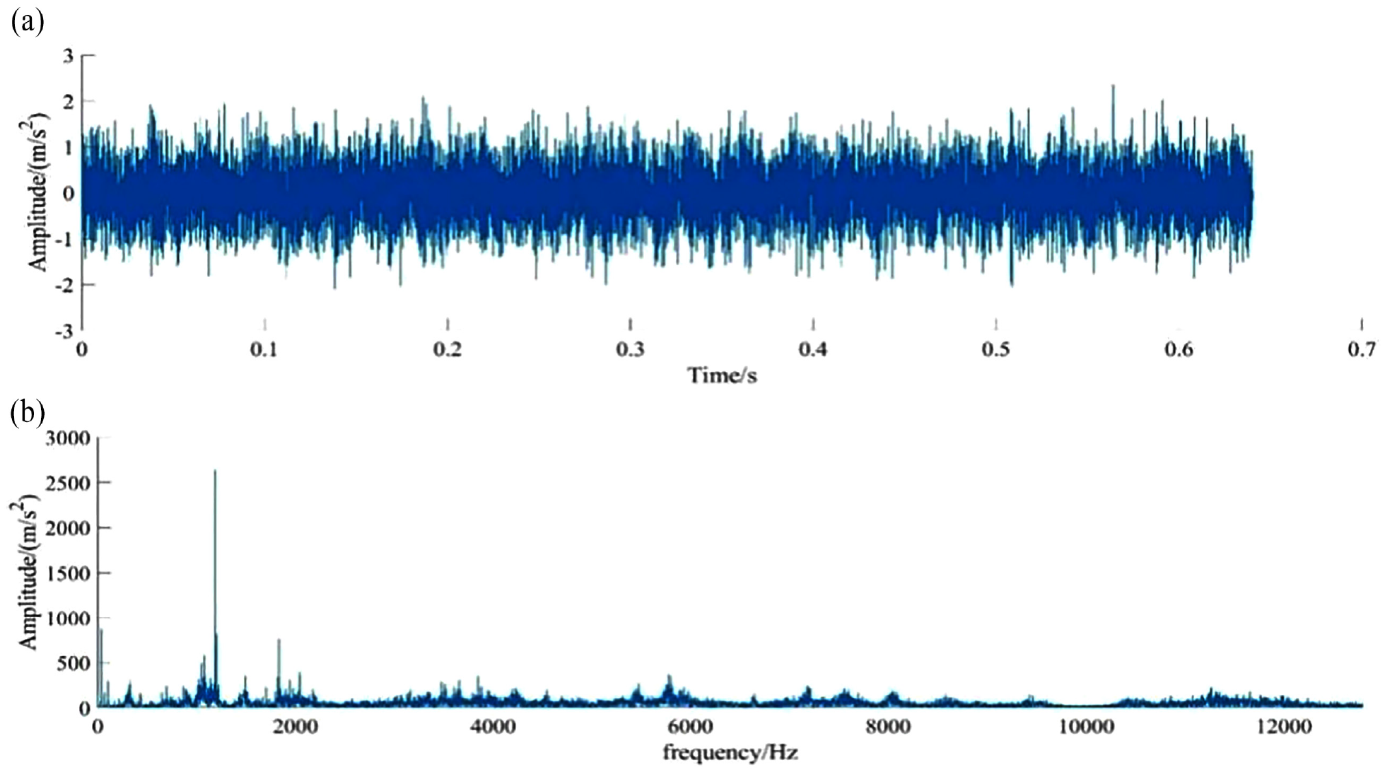
Finally, the experimental bench used is shown in Figure 2, experimental validation signal

Experimental test bench: (a) time domain diagram of gearbox fault vibration verification signal and (b) frequency domain diagram of gearbox fault vibration verification signal.

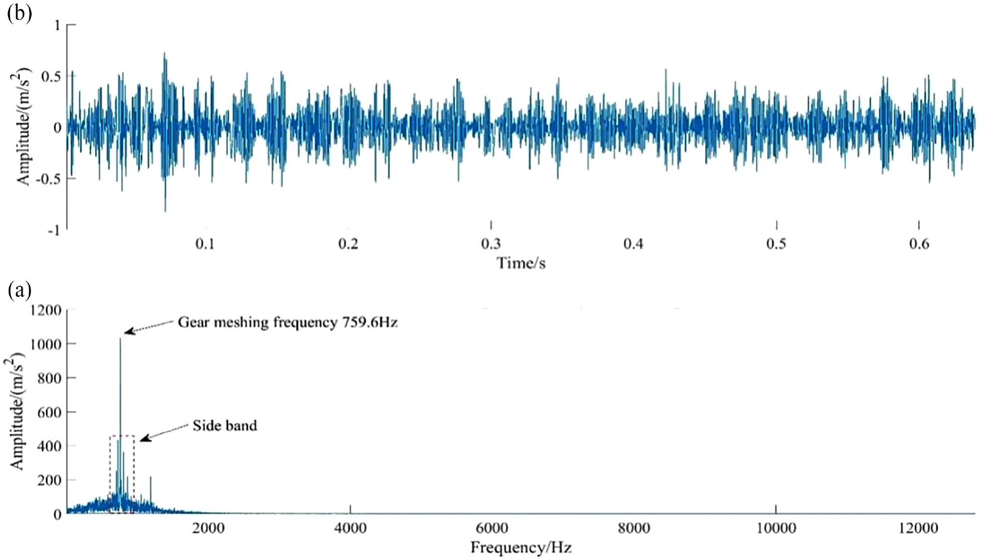
Gearbox compound fault vibration validation signal: (a) time domain diagram of gearbox fault vibration verification signal and (b) frequency domain diagram of gearbox fault vibration verification signal.
Periodic transients corresponding to rolling bearing outer ring fault: (a) bearing outer ring fault vibration signal time domain diagram and (b) bearing outer ring fault vibration signal frequency domain diagram.

Side frequency modulation component corresponding to gear fault: (a) time domain diagram of simulation vibration signal of simulated fault gear and (b) frequency domain diagram of simulation vibration signal of simulated fault gear.
Firstly, RSSD is performed on the validation signal

Signal decomposition based on RSSD: (a) high resonance component, (b) low resonance component, and (c) residual component.
In order to warn the incipient gear fault, we firstly perform local mean decomposition (LMD) on the high resonance component, and the its PF components is shown in Figure 7, and the corresponding spectrum is shown in Figure 8. It can be clearly seen from Figure 8 that PF3 component has obvious side frequency modulation feature corresponding to meshing frequency fm, while PF4 and PF5 components present significantly harmonic property. As a result, the proposed method uses PF3 component to combine a reconstructed signal to highlight gear fault information as shown in Figure 9.
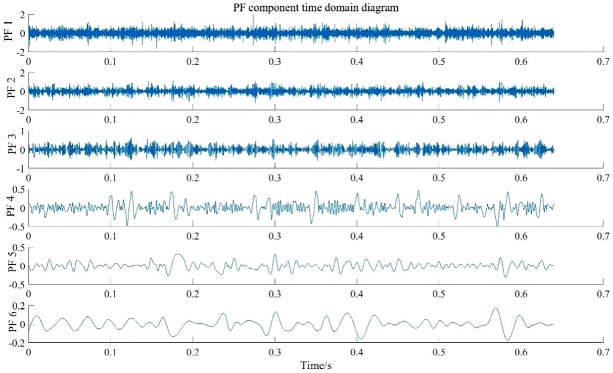
PF components corresponding to high resonance component.

PF components spectrum.
Reconstructed signal: (a) reconstruct the signal time domain diagram and (b) reconstruct the signal frequency domain diagram.
Finally, by inputting the reconstructed signal into Duffing chaotic oscillator and combining the two-dimensional approximate entropy, it can quantitatively identify the varying law of side frequency band and detect incipient gear fault consequently. Besides, the Duffing chaotic oscillator under a stable large-scale periodic state infers the gear works in normal operation as shown in Figure 10. However, when the gear overcomes the early fault degradation degree, accompanying with the gear fault deterioration deepening, the influence of side frequency band on the oscillator is strengthened which induces the state of oscillator gradually varies from large-scale periodic state to completely chaotic state (Figure 11). In this process, the two-dimensional approximate entropy is used to evaluate quantitatively fault degree. Finally, as shown in Figure 12, it can see that this healthy indicator plays a good role in gear early fault warning.

The oscillator phase plane corresponding to the gear healthy running state.

Variation diagram of oscillator chaos: (a) oscillator diagram of early failure of gear Ae2d = 0.0083, (b) gearbox oscillator diagram for normal operation Ae2d = 0.0087, (c) gearbox oscillator diagram for normal operation Ae2d = 0.0097, (d) gearbox oscillator diagram for normal operation Ae2d = 0.0114, (e) gearbox oscillator diagram for normal operation Ae2d = 0.0234, and (f) gearbox oscillator diagram for normal operation Ae2d = 0.0223.
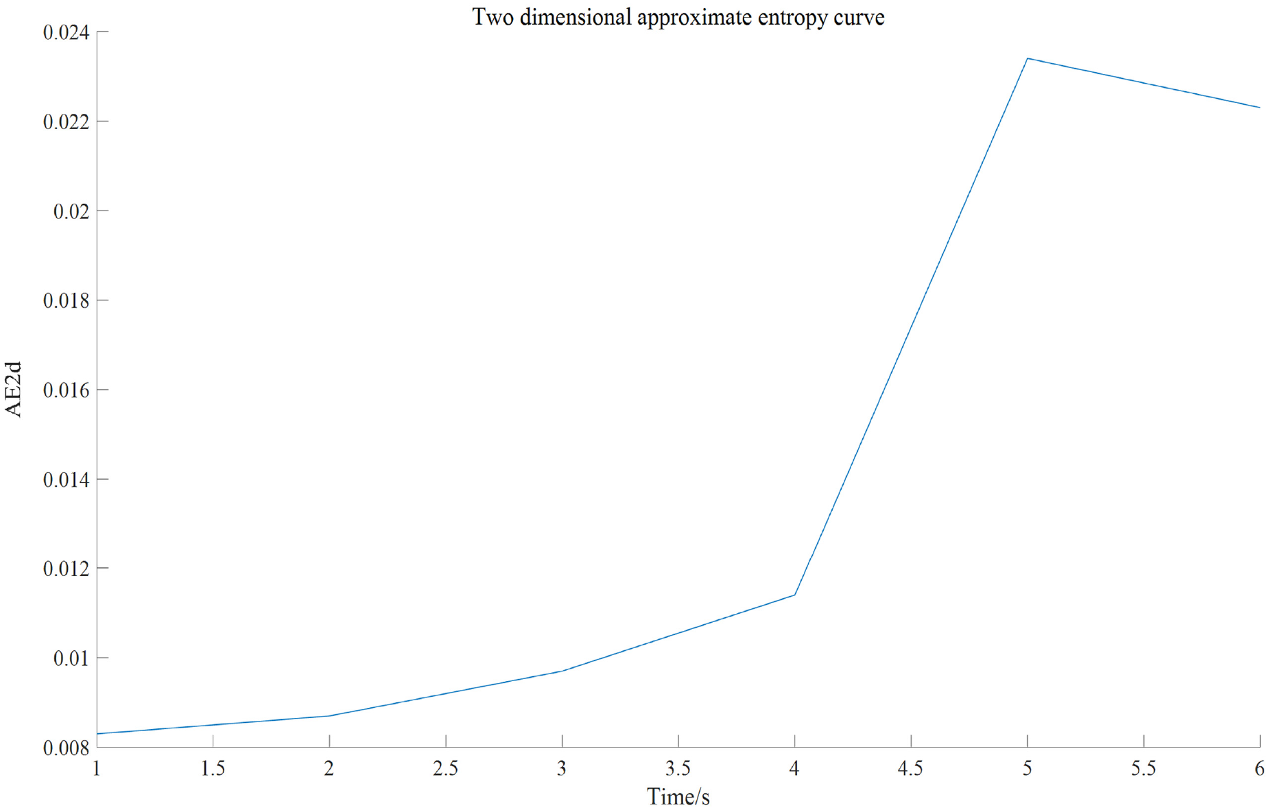
Two-dimensional approximate entropy varying law.
Simultaneously, SVD is used to improve the SNR of low resonance component containing rolling bearing fault information, and its singular value difference spectrum is shown in Figure 13. Considering the amplitude peak in singular value difference spectrum may be caused by rolling bearing fault, in order to avoid the interference, the first seven singular values are used to reconstruct the low-resonance component, as shown in Figure 14. By comparing Figure 14(b) and (c), it can see intuitively that the SNR of reconstructed signal is effectively improved by using SVD, while by analyzing the envelope spectrum of reconstructed signal, it is still affected by interference. As a result, the fault frequency still needs to be enhanced.

Singular value distribution curve and difference spectrum: (a) singular value distribution curve and (b) singular value difference spectrum.

Reconstructed low resonance component based on SVD noise reduction: (a) signal time domain diagram after denoising by singular value decomposition, (b) signal frequency domain diagram after denoising by singular value decomposition, (c) signal frequency domain diagram before denoising by singular value decomposition, and (d) Hilbert envelope spectrum of signal before denoising by singular value decomposition.
Therefore, cepstral pre-whitening is performed on the reconstructed low resonance component as shown in Figure 15 and Figure 15(a) shows the real cepstrum. Furthermore, spectrum editing combination with whitening processing is carried out by using the signal’s original phase, Figure 15(b) shows the time domain waveform by using whitening processing. It can be seen that the periodic transients are significantly enhanced, considering each frequency is equally important in the whole spectrum, so there is no optimal resonance band, and envelope analysis can be conducted directly. Therefore, the extracted envelope can input into stochastic resonance operator to identify fault frequency and its multiple frequencies, as shown in Figure 16. The actual fault frequency 106.9 Hz and its doubling frequency can be identified, which is consistent with the theoretically fault frequency
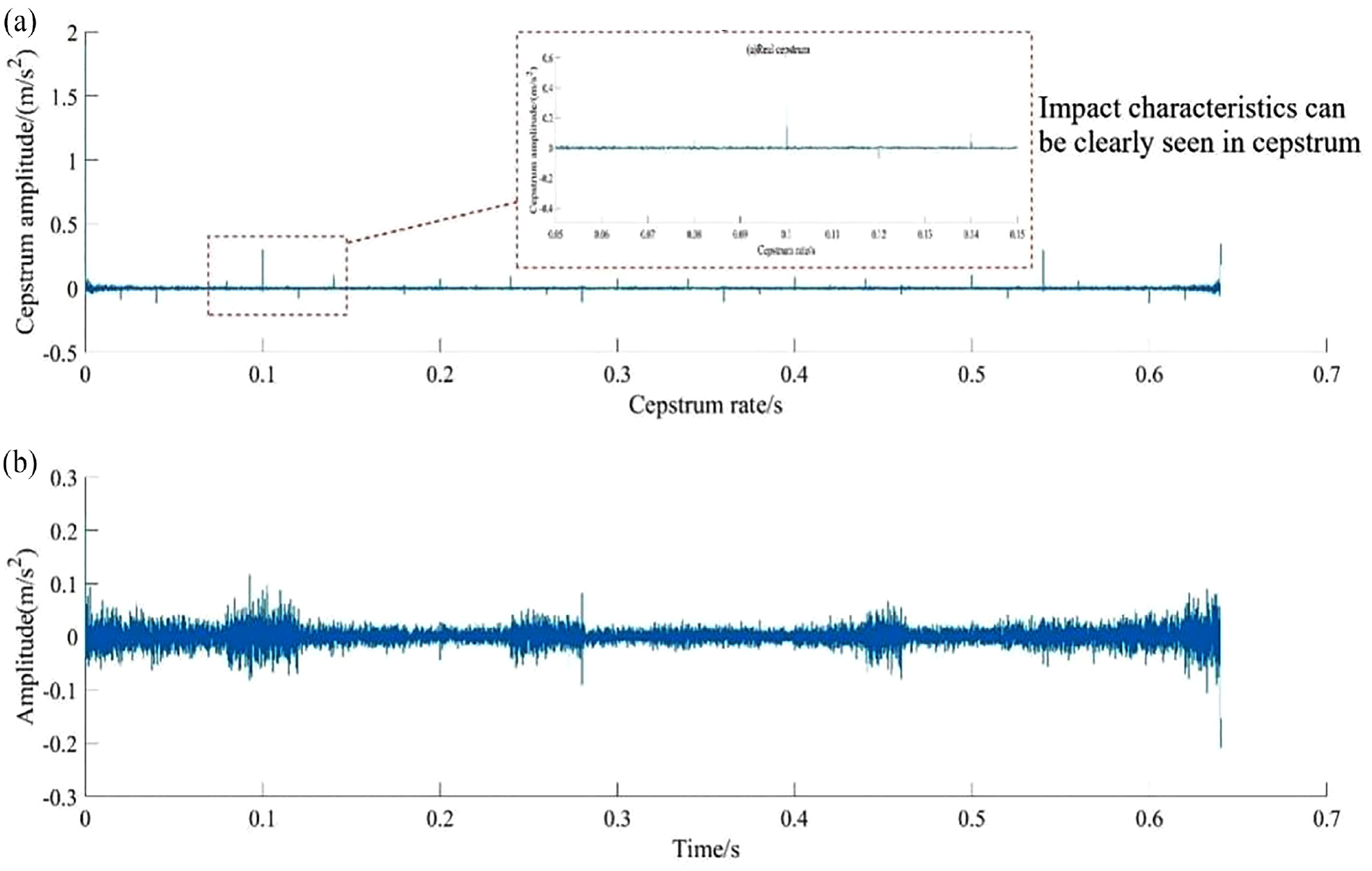
Real cepstrum and whitened signal: (a) real cepstrum and (b) Albino signal.
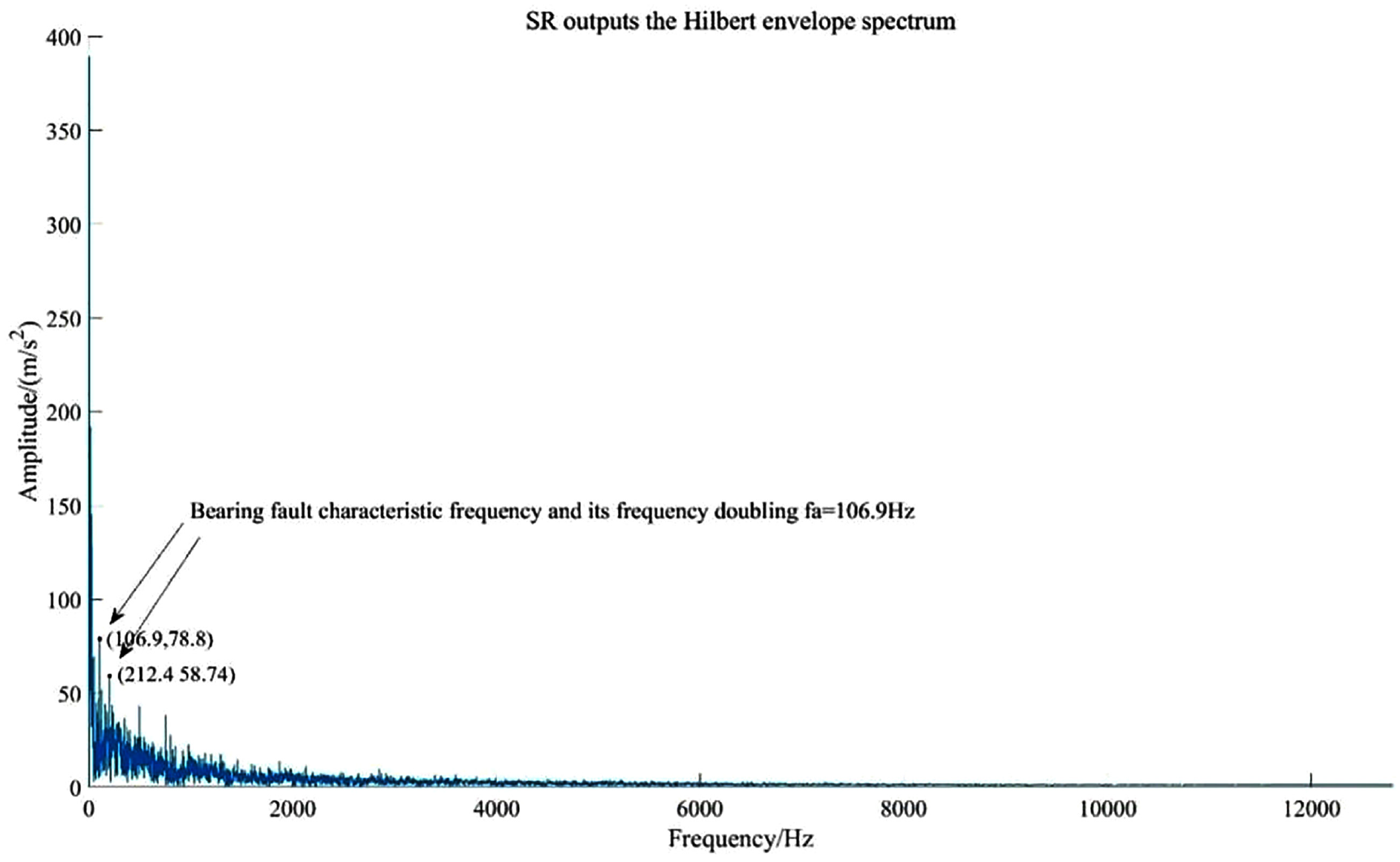
Stochastic resonance outputs the Hilbert envelope spectrum.
For comparison on gearbox compound fault diagnose effect, discrete wavelet transform (DWT) in the literature
7
is used to analyze validation signal
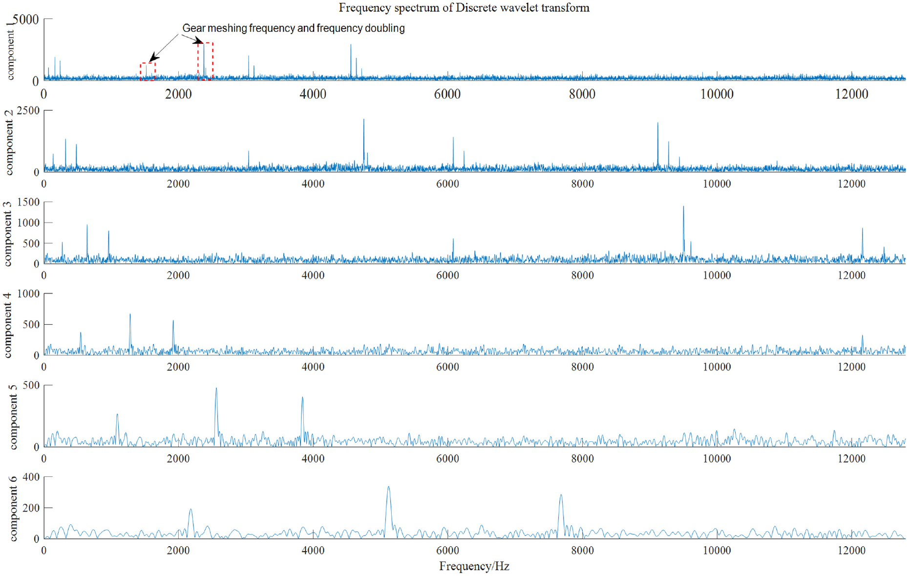
Frequency spectrum of validation signal
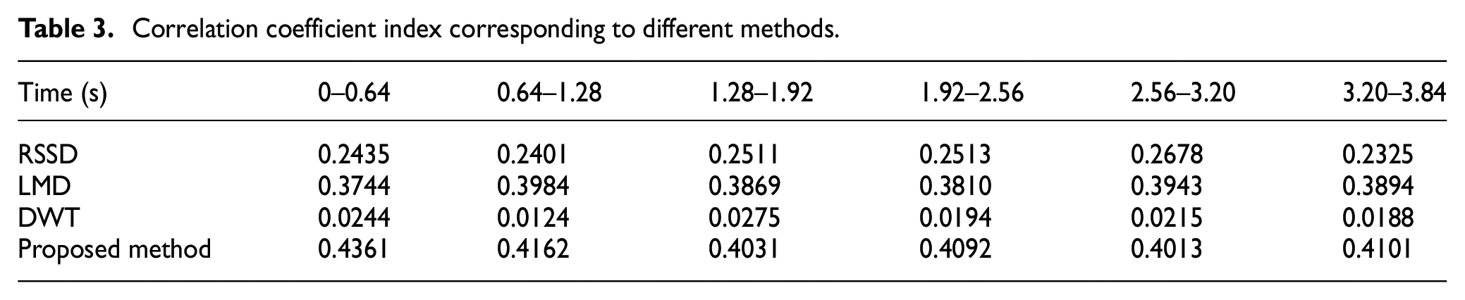
In order to further prove the accuracy and feasibility of proposed method quantitatively, it introduces kurtosis and correlation coefficient to evaluate the rolling bearing fault diagnose effect and gear fault diagnose effect respectively which is shown in Tables 2 and 3 respectively. Obviously, this result proves the superiority of proposed method.
Kurtosis index corresponding to different methods.

Correlation coefficient index corresponding to different methods.
System implementation
Gearbox compound fault diagnosis system mainly composes hardware device and software system. The hardware device contains industrial computer, data acquisition card, vibration acceleration sensor, and so on, as for software system, combination with LabVIEW and MATLAB, a software system based on the proposed gearbox compound fault diagnosis method is developed in this paper.
Hardware device
The hardware device composes IEPE vibration acceleration sensor, industrial computer, vibration signal acquisition card, as shown in Figure 18 which can realize four-channel vibration acceleration acquisition which varies from 0 to 50g and one channel rotating speed signal synchronously.

Schematic diagram of the hardware device.
Software system
The software system mainly focuses on evaluating the running state of gearbox, early fault warning, and key parts of gearbox fault identification. In specific, the running state of gearbox is evaluated by using vibration intensity and other indicators. In addition, in order to facilitate system modification and expansion in future, the software system is designed into four functional modules, namely, the login module, the signal acquisition module, the online monitoring module, and the fault diagnosis module and they do not interfere with each other, as shown in Figure 19.

Software system flow chart.
Login interface of the system (main interface)
In order to prevent data leakage and ensure the system security, the login module is designed. If there is an input error in the account number or password, the gearbox composite fault diagnosis system will pop up a prompt “The account number or password is entered incorrectly, please enter it again!” as shown in Figure 20.

Login interface of this system (main interface).
Signal acquisition module
In the software system, the acquisition module is completed through LabVIEW programming, which uses DAQmx to create virtual channels, DAQmx timing and other sub-VI settings acquisition channels, input voltage range, terminal configuration, sampling frequency, and other parameters. Besides, signal is stored in the format of TDMS file storage, as shown in Figure 21.
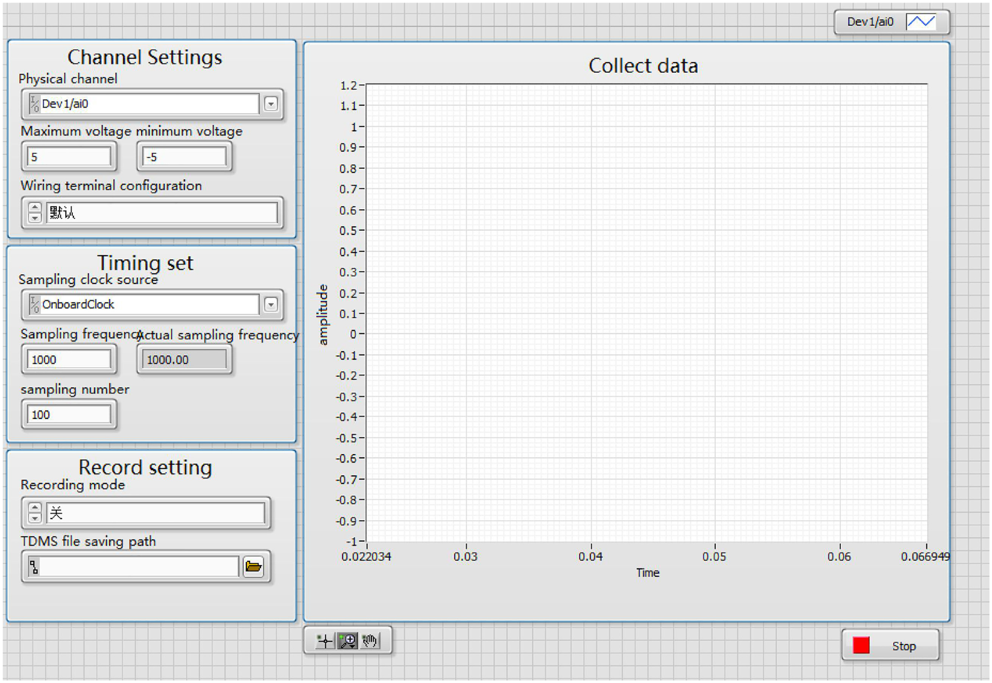
Acquisition module interface.
On-line monitoring module
The online monitoring module mainly covers time domain analysis, frequency domain analysis, and data preservation. As for time domain analysis, it contains gearbox fault early warning by using a series of indicators which are very sensitive and more intuitive to the gearbox health state as shown in Figure 22.

Online monitoring system front panel.
On the other hand, as for frequency domain analysis, it mainly includes amplitude spectrum, envelope spectrum, time-frequency analysis, Hilbert spectrum, and vibration severity. Especially vibration severity is the most important indicator to judge whether the gearbox occurs fault which is calculated from frequency

The data preservation function mainly stores the original fault vibration signal and a series of healthy indicators in the ACCESS database as shown in Figure 23.

Data preservation function.
Fault diagnosis module
The fault diagnosis module mainly uses the proposed method in this paper to decompose gearbox compound fault vibration signal, weak rolling bearing fault enhancement, early gear fault warning, as shown in Figure 24.
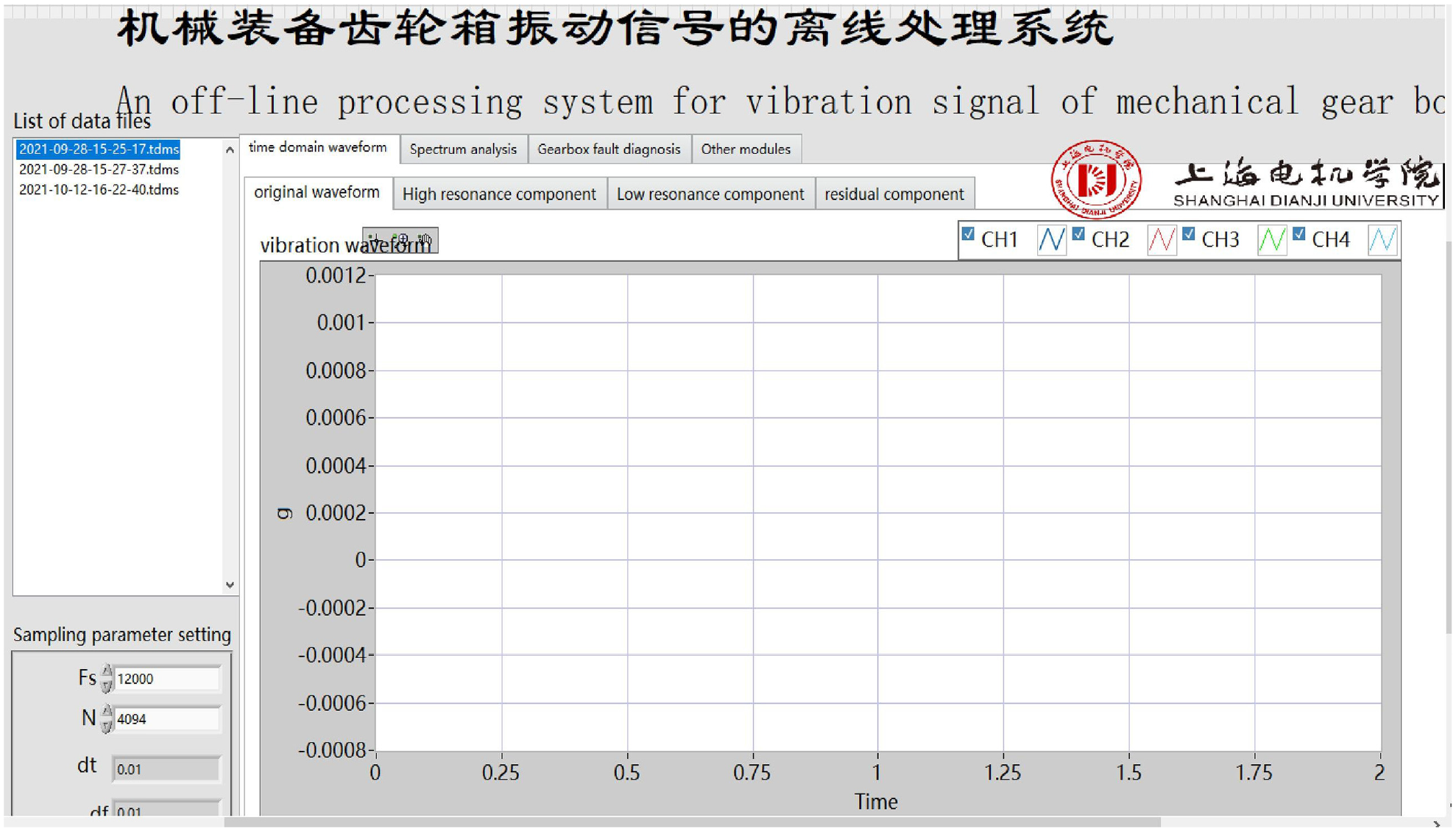
Fault diagnosis module.
Conclusion and prospect
Aiming at gearbox compound fault diagnosis, the proposed method can decompose fault vibration signal, enhance weak rolling bearing fault and achieve early gear fault warning, its feasibility and superiority also are verified by experiment. Finally, a diagnosis system is developed based on the proposed method ultimately, and a series of conclusions are obtained as follows.
(1) A gearbox compound fault diagnosis method is proposed. Firstly, it uses RSSD to decompose the fault vibration signal into signal components which contain rolling bearing fault information and gear fault information respectively. Then, weak rolling bearing fault is enhanced based on singular value decomposition combination with cepstral pre-whitening and stochastic resonance. Finally, by using local mean decomposition and Duffing chaotic oscillator, it can warn incipient gear fault and two-dimensional approximate entropy is used to quantitatively evaluate its fault deterioration degree.
(2) A gearbox compound fault diagnosis system is designed based on proposed method. This system uses LabVIEW and MATLAB software environment to develop a set of software and hardware which can realize the gearbox healthy status on-line monitoring and key components fault diagnosis and it can solve the problem that the existing fault diagnosis system can only be applied on a certain part.
For subsequent research, it is necessary to improve the signal decomposition efficiency based on RSSD, the software recently runs slowly when the signal number is large (the number of sampling points is more than 10 M). Secondly, based on the oscillator chaos combination with two dimensional approximate entropy, it can warn gear early fault based on analyzing side frequency modulation, while as the gear vibration signal in healthy state also presents side frequency modulation property, therefore, how to confirm the approximate entropy threshold is very important which still needs further research in future.
Footnotes
Handling Editor: Chenhui Liang
Declaration of conflicting interests
The author(s) declared no potential conflicts of interest with respect to the research, authorship, and/or publication of this article.
Funding
The author(s) disclosed receipt of the following financial support for the research, authorship, and/or publication of this article: This study is supported by the Lin-gang’s integration between industry and education public service project of Shanghai Dianji University (22B0203) and The Ministry of Education’s Cooperative Education Project (BINTECH-KJZX-20220831-51).