
Abstract
Fault diagnosis is of great significance for the rapid recovery of the system after the accident. Intelligent dispatching among multiple controllers is developed in this work to improve the efficiency of downhole locomotive dispatching, finally realizing unmanned intelligent locomotive dispatching. The locomotive dispatching logic processing model of with signal lights, rutting machine, locomotives, and other equipment is established based on the model theory of Cyber-physical systems (CPS). The model tasks in this system are combined with the embedded controller tasks which make it convenient to optimize the logic processing procedures using Ptolemy II software. Our key findings indicate that the proposed model can make the locomotive dispatching process without deadlock and make the processing procedure more reasonable. Simulation and practical experiments demonstrate that the controller cooperation speed can be improved after the CPS model is built, which can realize safer and more effective automatic locomotive dispatching.
Introduction
With the improvement of coal mine downhole level, there are more and more downhole intelligent equipment and intelligent controllers. However, the existing task division of controllers and coordination mechanisms between different controllers are inadequate to the envolving downhole environment and cannot achieve faster and safer unmanned automatic dispatching of downhole locomotives. As for now, there is a need to optimize the locomotive dispatching process. Concerning that the CPS (cyber-physical system) theory has many applications in solving the coordination of system process, we prefer to combine the cyber-physical system with various mining locomotive monitoring equipment to propose a multi-processor, multi-task scheduling locomotive dispatching and monitoring system, which helps to implement unmanned intelligent locomotive dispatching.
The cyber-physical system is highly integrated, monitorable, and controllable engineering systems with communication, computing, and control as the core, which realize the integration of virtual (information) and real (physical) worlds. 1 2–4 This three papers proposed effective fault detection and diagnosis algorithms based on different ways. The paper 3 also proposed a set of distributed solutions, which can prove the diagnosability achieved by the programs decentralized architecture and improve the diagnostic efficiency. However, this paper solves the problem of system fault through reducing information interaction, and does not specifically analyze the complex system fault. In this paper, the same idea will be adopted to the cyber-physical system as the scheduling scheme of system information interaction. Nowadays, the cyber-physical system has been applied in many aspects, and the most researched problem is the security issue. An et al. analyzed the security of human-computer-object fusion system by formal modeling and dynamic verification. In their paper, 5 Wang et al. 6 introduced the types of attacks and defense problems of the cyber-physical system in their paper, Yin and Li 7 presented a recent progress in using formal methods to verify the CPS security problem in their paper. It is found that the CPS model in different fields can better solve the safety problem of the system and will not bring the complexity of the physical level of the system. Also, it can continue to be applied to the mine locomotive dispatching system. In addition to the above security issues, there are also many papers that use CPS to improve the operational efficiency of the system, Yuan and Guo 8 implement collaborative scheduling of trucking vehicles to reduce fuel consumption through CPS in their paper. In their paper, 9 Jin et al. standardize the process of ship assembly welding operation through CPS to improve the efficiency of assembly welding. Liang and Chen 10 apply CPS to library management systems for intelligent libraries in their paper. The above research applied the CPS model to obtain the optimal scheduling solution. While in coal mine, only in 2011, some scholars introduced CPS theory in coal mine in China. 11 The paper proposed to introduce CPS theory to the whole coal mine production process. Li and Gong 12 proposed a new scenario-aware self-configuring system for coal mine cyber-physical system for the complex and difficult to fuse information in coal mine. However, it is not suitable for simple coal mine subsystem modeling. Except that, Gaber et al. 13 discussed cyber security and data security issues after the combination of mining and CPS in their paper. On the basis of ensuring safety, we will propose a suitable mine locomotive scheduling scheme.
The research objectives of this paper are to solve the functional safety problem of the downhole dispatching system and to improve the locomotive dispatching efficiency by coordinating controllers. First, we introduce the concept of Cyber-physical systems (CPS) and establish a CPS architecture for locomotive dispatching and monitoring. Then, we propose a processing logic modeling approach that caters to different situations encountered in the downhole dispatching process. This approach involves dividing the tasks among different controllers, enabling collaborative dispatching. Simulation experiments and practical verification are that CPS modeling is safe and effective, and can optimize the dispatching efficiency and make the program writing more reasonable.
Problem description of cyber-physical system for locomotive dispatching
With the improvement of the automation level of underground locomotive transportation in coal mine, the importance of mine transportation dispatching system in the safe running of downhole locomotive is increasing day by day. At present, on the one hand, the physical space (such as real-time dispatching equipment, monitoring equipment, transportation equipment, and other dispatching entities) and information space (such as intelligent control, information management, transportation replay, and other software systems) of the downhole dispatching system are isolated from each other, which requires a model to abstract the original scattered software and hardware control resources into network nodes and paths on the information space. On the other hand, the perception and calculation of mass production data and the dispatching of physical space can not be accurately controlled. The number and types of access equipment are increasing, and the amount of data to be collected, transmitted, and calculated is larger. Except that, the real-time industrial data is up to PB level, the amount of data is still growing exponentially. The internal traffic load of the entire production system network is large, which is easy to cause network congestion and eventually lead to the breakdown of the downhole locomotive system.
The cyber-physical system (CPS) is a system that consists of a combination of physical subsystems and computations and networks. Models of cyber-physical system typically include these three components, and these models need to represent both dynamic and static properties, which do not need to have both discrete and continuous components. A purely discrete (or purely continuous) model has the potential to allow the properties of interest to be maintained with high fidelity. 14
According to the above condition of underground downhole dispatching the above concept, it can be seen that the downhole locomotive dispatching and monitoring system is a cyber-physical system, in which the physical subsystem is the component of the locomotive monitoring system including the signal light that allows locomotives to pass, the rutting machine that changes the direction of locomotive travel, and the position sensor that monitors the locomotive position, etc. These can be regarded as the physical subsystem of the locomotive monitoring system. The computation part is the controller of the locomotive monitoring system. The physical subsystem and the computing part are connected by network cables, and the physical subsystem and the computing part themselves can also communicate through various wireless communication devices. Thus, the locomotive dispatching and monitoring system can be considered as a typical example of a cyber-physical system (CPS), forming a communication network that integrates the physical components and digital aspects of the system.
This paper studies the locomotive dispatching system through a formal approach. The physical subsystems of the locomotive dispatching and monitoring system are basically discrete components, using state machines to model discrete dynamics in CPS. As for state machines, each response maps a set of input valuations to a set of output valuations, which depend on its current state. By utilizing finite state machines, the scheduling logic of the physical subsystem can be effectively represented. These machines provide a systematic approach to capture the behavior of the equipment in various states. With a limited number of states, finite state machines serve as an appropriate modeling tool for understanding and optimizing the dispatching process in downhole locomotive operations. The functions of the cyber-physical system equipment for locomotive dispatching are described as follows:
Signal light: The signal light status is controlled by the dispatching system and changes to green or red. The green light indicates that the approach road ahead is free and the locomotive can run, while the red light indicates that there are cars ahead and the locomotive cannot move forward.
The rutting machine: The rutting machine is placed at a three-way junction, connecting two of the three different directions of the road. The rutting machine is commanded by the monitoring system to connect the two approaches to the front and rear of the turnout.
Position sensor: The position sensor can obtain the position of the locomotive on the track in real time, locate and measure the speed of the locomotive, and communicate the corresponding information to the main monitoring system.
When the finite state machine of CPS is studied, the finite state machine will be defined as the following five-tuple.

In the following, the logic of the physical subsystem of locomotive dispatching will be studied by means of formal modeling to form the above-mentioned update function. It also shows program optimization and process of improving the efficiency of system dispatching.
Cyber-physical system modeling of downhole locomotive dispatching
In the process of downhole dispatching, locomotives in different road conditions have different needs for various monitoring equipment. Indeed, the controller’s proficiency in efficiently and accurately managing the equipment’s logic under diverse road conditions plays a crucial role in ensuring the safety and efficiency of the entire dispatching process. The interface of coal mine locomotive dispatching studied in this paper is shown in the following figure:
Figure 1 shows the upper computer interface of the downhole locomotive monitoring system of a mine, where the blue route represents the locomotive track, the various icons near the track represents the different devices of the locomotive dispatching and monitoring system, and the numbers on the track represents the divided sections. There are four paths for locomotives in this mine. Route 1 is for mining locomotives to enter the track from Pingdongkou 01# yard and finally arrive at 303 plate area 03# yard, route 2 is to return from 303 plate area 03# yard to Pingdongkou 01# yard, route 3 is for mining locomotives to enter the track from Pingdongkou 01# yard and finally arrive at 303 plate area 02# yard, and route 4 is for locomotives to return to Pingdongkou 01# yard from 02# yard in 303 plate area. The approach and section division of this mine are shown in Table 1:

Locomotive coal mine interface diagram.
Route and section correspondence table.

Locomotive route control logic model
Based on the above description of the mine locomotive path, the locomotive is driven according to the locomotive dispatching rules. It is found that there are three situations in which the locomotive is driving on the track and need to be processed logically.
Case 1 is that the locomotive is traveling on a single track through a different approach. Case 2 is that the locomotive changes its track after passing through the turnout section. Case 3 is that the locomotive passes through different sections when driving on the approach. Within the given states, cases 1 and 2 both require a variety of monitoring equipment to coordinate their traffic logic. In addition, case 3 is only related to the position sensor and only involves the interior of the approach whose logic is simple and does not require special analysis. Therefore, only cases 1 and 2 are analyzed in the following. The Ptolemy II 1 software is a highly reliable system-level open source design platform, which is suitable for modeling the above cases as a modeling and simulation tool for designing parallel, real-time, distributed systems. Case 1 is a locomotive entering the first section of the next approach from the last section of the current approach. Each approach is separated by signal light. Its state machine modeling in Ptolemy II is shown in Figure 1.
From Figure 2 it can be seen that the equipment involved in case 1 are position sensors, locomotives, and signal lights. It can be seen from Figure 2 that the equipment involved in case 1 includes sensors, locomotives, and signal lights. The position sensor output does not involve the controller, so it only focuses on the state changes of locomotives and signal lights. In this case, the dispatching model is shown in Figure 2. In this process, the locomotive has three inputs, which are the signal light when the locomotive is entering, the sensor1 when the locomotive is entering, and sensor2 when the locomotive is leaving. An output reply is the command sent to the signal light, replyA and replyB are different command requests sent to the signal light according to the location of locomotiveA.

System model for locomotives passing through different approaches.
The four logical state changes of the locomotive in this case are shown in Figure 3. When the locomotive enters the last section of the current approach road, sensor1 informs locomotive A that it will arrive at the signalized intersection and can request to enter, at this time reply = wait. Then when it arrives at the signalized front, at this time if signal = red, continue to wait. If signal = green, the state of locomotive continues to become After L, reply = inside, indicating that the locomotive is in the post-signal section. Then, when the locomotive enters the second section of the new approach, sensor 2 will inform the locomotive that it has left the signal area and send the reply = leave command.

Finite state machine of locomotives through approaches.
The finite state machine of the locomotive in that case can be expressed in the following mathematical form:


For all of the

The status change of the signal light in this situation is shown in Figure 4:

Finite state machine for approach signals.
In this case, the signal light is affected by both the locomotive before the signal light and the locomotive after the signal light. There are two inputs in Figure 2, where reply A is the locomotive application command for the approach before the signal light, and reply B is the locomotive application command for the approach after the signal light. From the logic state diagram in Figure 3, it can be seen that when the locomotive applies for reply B = inside state, the state and output of the signal light are red. When the locomotive applies for reply B = leave, the signal light status and output change to green. When reply B = leave and reply A = absent, the signal light status and output are still green. When locomotiveA enters the back of the signal light from before the signal light, that is, when the locomotive applies for the command reply A = inside, the signal light changes to red.
The finite state machine of the signal light can be expressed in the following mathematical form:


For all of the

Locomotive switch section control logic model
In case 2, the locomotive passes through the turnout section to select the driving track, requiring the rutting machine, signal light, locomotives, and sensing controller devices to participate in the dispatching at the same time. In this case, it is crucial to coordinate the logic of multiple devices, which encompasses addressing the locomotive priority problem, locomotive conflict problem, and potential deadlock issue of the whole locomotive dispatching process. Therefore, the correct handling of the device logic relationship in this case determines whether the whole dispatching process can be safely executed. The situation is modeled in Ptolemy II with a state machine modeling model as shown below:
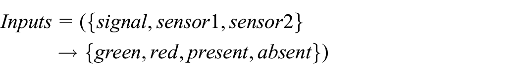
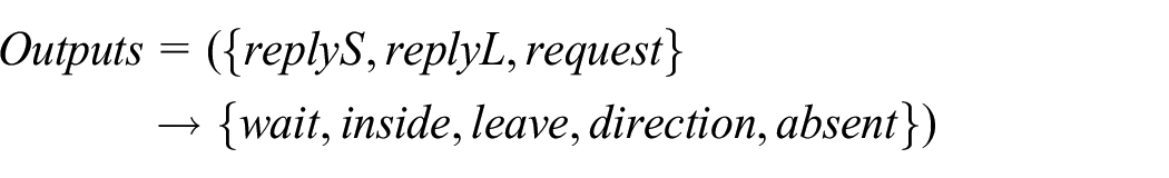
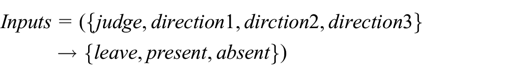
The case corresponds to the approach to the rutting machine in Figure 1 and is similar to the model in Figure 2, where again there is no need to focus on the position sensors and additionally the logical state of the rutting machine needs to be analyzed. The dispatching model in this case is shown in Figure 5 and the general logic is similar to that of case 1. There are three types of inputs, signal light of the turnout section signal, sensor which detects the locomotive entering sensor1, and sensor or signal which receives the command for the locomotive to leave the turnout section. There are three kinds of outputs with the corresponding, the command sent to the signal light reply L, the command sent to the rutting machine reply S, and the direction request of the locomotive request.
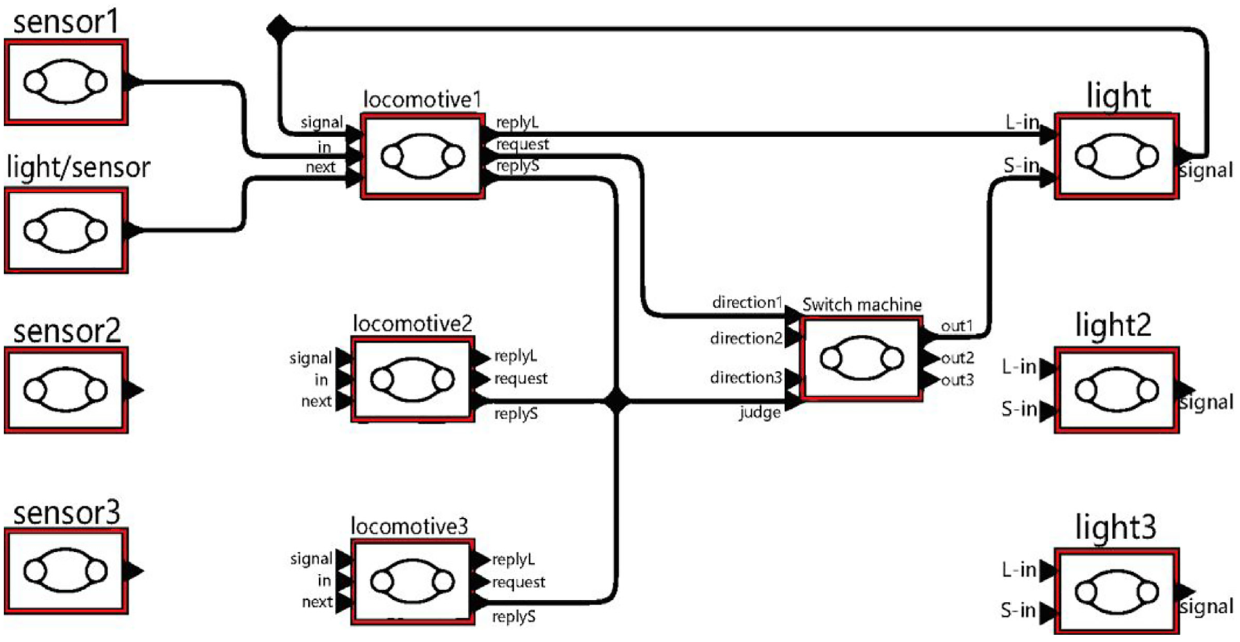
Scheduling system model of turnout sections.
The state change diagram of locomotive in turnout section is shown in Figure 6. When the locomotive enters the last section before the turnout, sensor 1 detects the locomotive entering and allows it to send a request for direction of travel to the rutting machine request = direction, and then the locomotive reaches the signal light of the guarded turnout section, in which the state is before L. At this time, if signal = red, it continues to wait until signal = green, the locomotive enters the area inside the turnout section and sends reply L = inside to the signal light. Until the light or sensor in NEXT detects that there is no locomotive in the next approach to the turnout section, the locomotive leaves the turnout section and tells the rutting machine to reply S = leave.

Finite state machine of turnout section locomotives.
The finite state machine of a locomotive entering a turnout area can be expressed in the following mathematical form:


For all of the

The signal light logic state diagram for the turnout area is shown in Figure 7 below:

Finite state machine of turnout area signals.
The logic in this case is similar to that in case 2, but the signal light input is different from the signal light in the approach case. The judgment logic is mainly controlled by the rutting machine input command S-in and the locomotive application command L-in. If the rutting machine logic is not satisfied, the signal light outputs signal = red, else if it is satisfied, signal = green. In addition, when the locomotive enters the inside of the turnout area, L-in = inside, then signal = red.
The finite state machines for the signal light of turnout area can be expressed in the following mathematical form:


For all of the

The logical state diagram of the rutting machine is shown in Figure 8:

Finite state machine of turnout area rutting machine.
As illustrated in Figure 8 above, the rutting machine receives messages from locomotives up to three directions. Once the controller logically processes the locomotive information, it sends messages to the signal light in that direction to allow the locomotive to enter. In the logical relationship of this rutting machine, if only one locomotive is requested, it is allowed to enter the turnout, and if more than one locomotive is requested, the priority of locomotives is locomotive 1 > locomotive 2 > locomotive 3. Of course, the priority of locomotives can be changed according to the optimal scheduling strategy. Besides, the rutting machine starts to process the locomotive’s direction request only when there is no locomotive in the turnout area, that is, when judge = leave.
The finite state machine of the rutting machine for turnout area can be expressed in the following mathematical form:


For all of the

The entire downhole locomotive dispatching CPS is modeled by combining the models in the above two cases, which are modeled as shown in Figure 9 below.

Logical command system model of downhole locomotive dispatching.
In the figure locomotives A, B, C represent the three cases of locomotive in the downhole track travel, which occur during the actual logic processing. Ensuring the correct handling of the logic in these three cases is of importance in order to guarantee the safety of the system’s overall logic.
Device task assignment in the controller
The logic of equipment operation in each case has been modeled in the section above. While in the actual downhole mine shown in Figure 1, the number of logic tasks similar to case 1 is known by the division of sections and approaches in Table 1 that there are a total of seven similar cases, and the logic tasks similar to case 2 are known by the number of rutting machine that there are 10. Except that, the state change of the position sensor does not require complex processing by the controller and not need to be join the task. If all tasks above the process of downhole locomotive scheduling occur, it will make the state change of downhole equipment 217 times. As it can be seen, so many equipment states cannot be simply by one or a few controllers to add up the processing, which requires the task allocation between different controllers and coordinate their logical processing order.
In fact, the actual situation may be that the downhole locomotive capacity is limited and many states violate the basic logic may not occur. Even that there are at least 210 kinds of downhole equipment states. In this case, the task allocation of the controller and the coordination between different tasks are very important. This paper mainly studies the KJ654 locomotive dispatching and monitoring system. According to the division of this downhole area, different areas are assigned to different areas to handle the logic of the area. In this system, seven substations have been set up to manage the equipment logic occurring in the above situation, in which the order of logic processing is coordinated between these substations through the network cable connection, forming a perfect physical fusion system of locomotive dispatching information.
CPS model simulation experiments and practical verification
After modeling the whole locomotive dispatching system equipment logic by Ptolemy II, whether the logic of this model is reasonable and can guarantee the security of the whole locomotive dispatching CPS still needs to be simulated and experimentally verified.
Simulation analysis
The process of simulation and analysis follows the classification of content modeling above, and the simulation tools are still available through Ptolemy II.
Case 1 has position sensor, locomotive, and signal light three devices, where the position sensor logic does not involve the control of the controller. Therefore, it is only necessary to check the logic of the locomotive and the signal to see if the logic modeling output is the same as the theoretical mathematical form. Simulation model chooses the model of Figure 2 in case 1, in which the output port placed display module to simulate the sensor to send information. To facilitate expression the process of detection, the input, output, and judgment conditions in Figures 3 and 4 are changed to digital. In this paper, set the present of the sensor to 1, absent to 0, and signal red to 0, green to 1. Additionally, reply are denoted as −1, 0, and 1 respectively representing wait, inside, and leave. As the results can manifest in four different states, the number of tests is set to four times, as shown in the following Table 2.
Locomotive state simulation test table.

The above Table 2 shows that there are some problems with the equipment logic of the model. Such as test number 2, 4, 7, 8 is logical, but the other four have no output. Furthermore, number 1 and 5 is also logical, because there is no locomotive in that case. However, number 3 and 6 should have output. The reason is that when the locomotive has entered the next approach, the locomotive was in case 3, where the locomotive travel logic was not related to the signal light but only to the position sensors. However, the locomotive state diagram in case 1 Figure 3 omits the constraints of the position sensors inside the approach for the locomotive. The logic inside the approach is adjusted in the overall modeling of the locomotive dispatch CPS in Figure 9 to solve the problem.
Similarly, the state machine of the signal light is tested in the following table:
As shown in Table 3, according to the locomotive driving rules and signal logic, locomotive B is driving in front of locomotive A and overtaking is not possible, and the locomotive requests the command reply A < reply B. So that only number2, 7, 8 can happen. But the number2 case has a red and green light switching situation, which is not reasonable. After testing, it is evident that there exists a time interval for the switch to occur in the actual situation. It is observed that the signal color does not frequently switch within a short period of time. The test result is in line with the actual signal logic.
Signal light status simulation detection table.

The modeling simulation test process and its locomotive logic for case 2 is similar to case 1. The rutting machine model can be viewed as a purely mathematical priority selection problem .Therefore, in this test only need to test if the signal light logic can ensure the safety of the turnout area. The test table is shown in Table 4 below:
Signal light status detection table of turnout section.
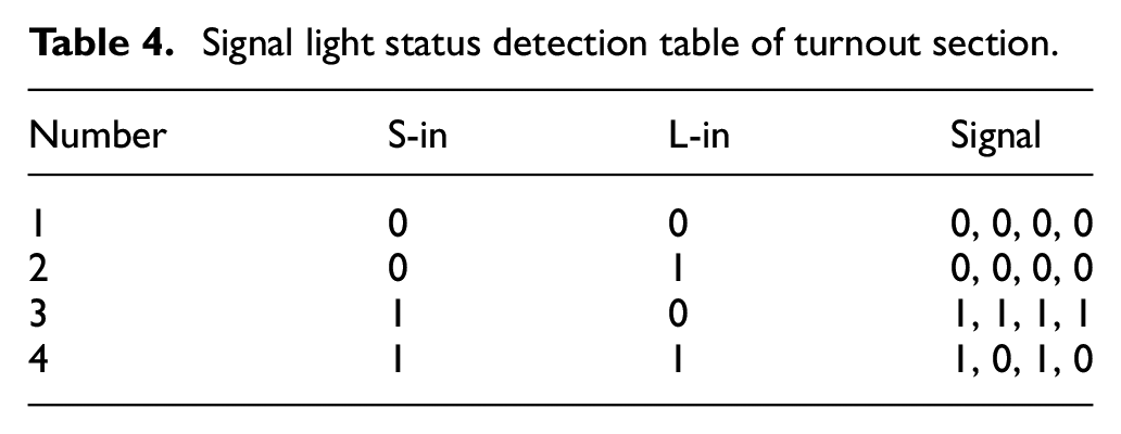
As shown in Table 4, the number4 case is similar to the previous case and there is reasonable. But a discrepancy arises when the signal input S-in is 0, indicating that the locomotive has not yet left the turnout section. This inconsistency contradicts with the model logic. So that if the above logic can be executed properly, the signal must be green when the locomotive enters the turnout section for the first time.
After the above simulation verification, the model in Section “Problem description of cyber-physical system for locomotive dispatching” is able to guarantee the functional safety issues of the locomotive scheduling CPS. The following will demonstrate through practical verification that the locomotive scheduling controller can quickly process the scheduling logic and significantly enhance scheduling efficiency after reasonable allocation of logic tasks.
Practical validation
In the actual mine locomotive dispatching system, the logic of the above model needs to be assigned to different controllers. It is necessary to understand the entire locomotive dispatching process, 15 and then propose an overall dispatching strategy. In the actual verification process, the KJ654(A) locomotive in a mine of Wangping was selected as transportation scheduling environment, and the route control information was selected as the interactive content. In the CPS system, the edge controller uses STM32F407 as the main control chip, and the command execution equipment such as switch machines and sound and light signal lamps uses C51 as the controller. Optical fiber communication is used between regional edge controllers, supplemented by industrial switches. Firstly, the scale of the information interaction model in the mine is compared between the locomotive dispatching cyber-physical system and the traditional dispatching and transportation system.
The locomotive transportation dispatching CPS system can run normally in accordance with the locomotive dispatching rules, and there is no deadlock and livelock, which verifies the correctness of its functional attributes. It can be seen from Table 5 that the control decision device and data processing device in CPS system have been greatly increased, which has improved the system data processing and control decision-making capabilities. Since the device controller in an actual locomotive dispatching system can be used as a virtual physical device controller with multiple information logic processing functions, the instruction execution device in the CPS information interaction model will not increase the actual physical execution device while increasing the reliability of system in task execution.
Scale of route switching information model.

From the perspective of information transmission response time of the CPS system, the information transmission time and data calculation time between controllers are related to specific hardware devices. CAN bus is used between the regional edge controller and instruction execution device. UWB communication is used between the locomotive and the regional edge controller. The communication delay is determined according to different communication methods and distances. The locomotive transportation dispatching systems in mine site are classified as 485 bus, WIFI mode, and independent bus according to the information transmission medium, all of which adopt centralized monitoring mode to realize locomotive dispatching. Compare the route functional performance of locomotive transportation dispatching system route under different types, as shown in Table 6 below.
Route function performance comparison of different types of locomotive transportation dispatching system.
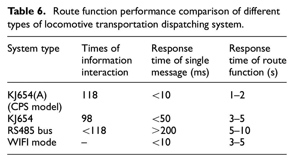
In Table 6, in terms of information transmission quantity and dispatching function response time indicators, the locomotive dispatching information transmission quantity based on the interaction model is less, information transmission reliability is high, and dispatching function response time is short. It can be seen that the locomotive dispatching strategy controller proposed in this paper through the finite state machine combined with CPS interactive control model can solve the logic processing problem quickly and safely. Besides, the degree of automation has been significantly improved.
Conclusion
This paper combined the theory of CPS model with downhole dispatching and monitoring system. A CPS (Cyber-Physical System) model was proposed for actual locomotives traveling on downhole tracks under different conditions. This model enables the assignment of downhole dispatching tasks to different embedded processors, finally realizing an intelligent locomotive dispatching system. The practical experiments established proves the safety and effectiveness of the model, which provides ideas and methods for fully intelligent automatic dispatching of downhole locomotives.
Footnotes
Handling Editor: Chenhui Liang
Declaration of conflicting interests
The author(s) declared no potential conflicts of interest with respect to the research, authorship, and/or publication of this article.
Funding
The author(s) received no financial support for the research, authorship, and/or publication of this article.
Data sharing statement
The datasets generated during and/or analyzed during the current study are available from the corresponding author on reasonable request.