
Abstract
The bushing of the trailing arm on torsion beam suspension plays a pivotal role in vehicle dynamic behavior. In this paper, the connection between bushing position and vehicle dynamic response is elucidated. According to the simulation results, the impact of the bushing position on the transient performance of vehicle is more pronounced at low handling frequencies, and different index under the same bushing position are not always optimal. To design the bushing position that is better for evaluation indexes, this paper formulates the design problem of the bushing position as a multi-objective optimization problem. Due to the influence of actual production and processing, inevitable errors in bushing position may result in vehicle performance not meeting design requirements. Therefore, this paper takes into consideration the uncertainties and conducts robust multi-objective optimization to design the bushing position. To address the computational burden associated with robust optimization, the RBF approximation model is developed in this paper. Finally, the optimization problem is solved with the NSGA-II intelligent algorithm. The optimization results show that the bushing position designed by robust multi-objective optimization results in vehicle with stronger anti-roll performance and better robustness for each evaluation index. It is more suitable for practical applications.
Keywords
Introduction
As one of the crucial component in modern vehicle, suspension plays a pivotal role in determining vehicle performance. The performance of suspension is ultimately reflected in the performance of the vehicle, and a rational suspension design requires comprehensive consideration of suspension characteristics and vehicle performance. On the other hand, in practical vehicle systems, there are numerous uncertainties, and assumptions of determinism may result in designs that do not meet requirements. 1 Therefore, it is increasingly necessary to consider uncertainties in the vehicle system in the research of suspension and vehicle.
Some scholars have considered uncertainties in vehicle design and have conducted research in this field. Wu et al. 2 used the hard point coordinates of double wishbone suspension as design variables and uncertain parameters. The uncertainty of the hard point coordinates was described by an interval uncertainty model. A Chebyshev approximation model was developed and the kinematic characteristics of the suspension were optimized. Shi et al. 3 conducted a study on the MacPherson suspension system, which involved establishing a relationship between the suspension hardpoints, spring stiffness, tire radial stiffness, and front wheel alignment parameters using the support vector regression method. Afterward, a multi-objective optimization function based on interval analysis was formulated, and a novel multi-objective particle swarm optimization algorithm was designed for the robust optimization of the suspension hardpoint coordinates. Drehmer et al. 4 developed an interval-based approach for multi-objective robust optimization, which was applied to optimize a 15DOF model of vehicle dynamics. Unlike traditional robust optimization methods, the proposed algorithm uses non-probabilistic Rx-cut interval analysis for quantifying uncertainties. Ma 5 performed non-deterministic optimization based on interval modeling with suspension hardpoint coordinates as uncertain design variables and the toe and camber angles as optimization objectives. Chen et al. 6 proposed a dual-loop particle swarm optimization algorithm to optimize the structure of longitudinally connected air suspensions under uncertain operating conditions.
The torsion beam suspension is a type of suspension system that is commonly used in passenger cars due to its simple yet effective design. Compared to other complex suspension systems, the torsion beam suspension boasts a high space utilization rate, which makes it a preferred option for automakers seeking to optimize space within the vehicle. Academic studies have been carried out on the topic of torsion beam suspension as well. Jiang et al. 7 employed a rigid-flexible coupled vehicle simulation model to achieve the lightweight design of torsion beam suspension. The optimization objectives were the weight the components of the suspension, whereas the constraint conditions were their fatigue life, stiffness, and modal frequency. Wang et al. 8 performed a lightweight design of the torsion beam suspension by optimizing the mass and deformation of the suspension system under typical working conditions while considering the constraints of strength, torsional stiffness, and the main vibration mode frequency. Albak et al. 9 developed a simplified optimization model for torsion beam suspension, in which the optimization objective is the mass of the torsion beam, and the front camber angle, caster angle, and inclination angle of the vehicle are treated as constraint conditions. Zhan et al. 10 investigated the fatigue behavior of a torsion beam suspension by measuring the deformation in the weld zone using digital image correlation (DIC) technique and performing numerical simulations with finite element analysis. The results demonstrated the potential of DIC technology in predicting fatigue damage. Zhao et al. 11 conducted a study on the operational position and operational critical load of a torsion beam suspension. Revealing that fatigue failure is more likely to occur in the torsion beam near the welds with reinforcement. Mun et al. 12 presented a novel analytical approach to predict the torsional stiffness of a beam based on its cross-sectional area. The effectiveness of this method was confirmed by comparing its results with those obtained using ADAMS (Automatic Dynamic Analysis of Mechanical Systems) software. The study findings demonstrate the potential of the proposed approach in predicting the torsional stiffness of beams with high accuracy. Lee and Yang 13 proposed a methodology to analyze the roll behavior of torsion beam suspension by calculating the torsional stiffness under different loading conditions. Jeong et al. 14 achieved an enhancement in the dynamic performance of a vehicle by optimizing various geometric parameters of a torsion beam, including the length of the upper and lower flanges, the thickness of the web, and the vertical height difference between the inside and outside of the beam cross-section.
From existing research on torsion beam suspension, it can be observed that current studies on torsion beam suspension primarily focus on light weighting, fatigue analysis, and the characteristics of torsion beam suspension itself. On the other hand, the bushing of trailing arm, as a critical connecting structure between the suspension and the vehicle body, has a significant influence on vehicle dynamic behavior. In practical production of torsion beam suspension, unavoidable errors in the processing and manufacturing of various design parameters may cause deviations in the design parameters. Therefore, considering the uncertainties in design the position of trailing arm bushing is of great significance for improving the dynamic behavior of vehicle. In light of this, this paper considers the transient handling performance of the vehicle and uncertainties as well as combining multi-objective optimization with robust design to obtain the position of the bushing. Specifically, this paper focuses on: (a) considering the transient performance of vehicle and the uncertainties; (b) the RBF (Radial Basis Function) neural network model is employed to approximate the mapping relationship between optimization variables and objectives to enhance computational efficiency; (c) transforming the design of bushing position into a deterministic and robust optimization as well as solving it by NSGA-II (Non-Dominated Sorting Genetic Algorithm-II) intelligent algorithm.
Mechanism of the impact of the position of trailing arm bushing on vehicle handling dynamics
Vehicle handling dynamics model
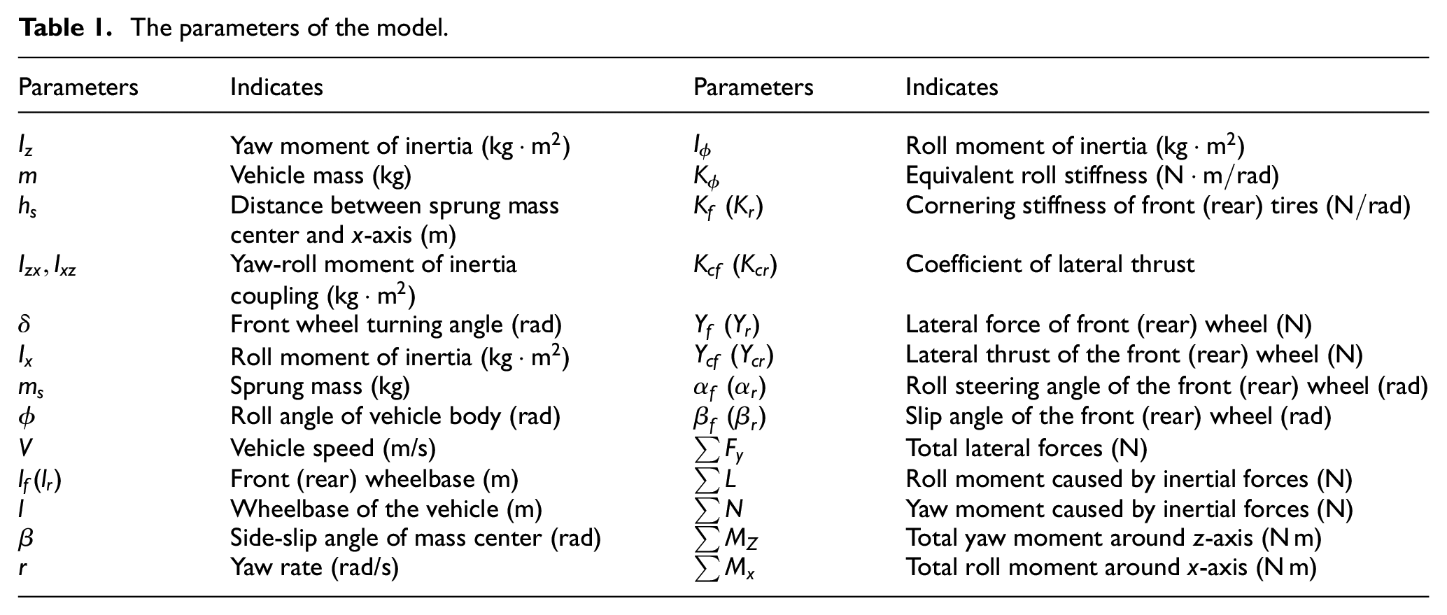
In the study of vehicle handling dynamics, a 3DOF vehicle handling dynamics model considering lateral, yaw, and roll motions as shown in Figure 1 is commonly used. 15 The main parameters of the model are presented in Table 1.

3-DOF handling dynamics model: (a) external forces acting on the tire and (b) roll motion of vehicle.
The parameters of the model.
The expressions for the total lateral inertia force

In addition to the lateral force

Equation (3) can be used to describe the lateral thrust in equation (2).

When taking the roll motion of vehicle into account, the actual wheel turning angle should not only consider the front wheel turning angle specified by the driver as an input, but also the influence of the roll motion of the vehicle. In this case the front and rear wheels will have an additional lateral steering angle due to the roll of the vehicle, in which case the side slip angle of the front and rear tires can be expressed as

When the lateral acceleration is lower than 0.4g (g is gravitational acceleration) and the impact of load transfer on the side slip angle is neglected, the lateral force

By combining equations (1), (2), (3), (5) and the equilibrium condition

Where

By applying a Laplace transform to equation (6) yields:

The transfer functions of


By utilizing equations (1), (10), and (11), the transfer function that calculates the lateral acceleration in relation to the front wheel angle

The equations (9) and (12) can be used to obtain the transfer function of ϕ with respect to lateral acceleration

The force analysis of a twisted beam suspension
Figure 2 shows a simplified diagram of the torsion beam. The trailing arm and the wheel knuckle are connected at point

Simplified diagram of the torsion beam.
The ground exerts forces and moments on the wheel knuckle, which are denoted by

In the case of

The forces

As the global and local coordinate systems may not be coincide, the position of the bushing is usually represented by a cosine matrix. The cosine matrix can be presented as:

The impact of the bushing position on the cosine matrix
Connection between the bushing position and handling of vehicle
The impact of suspension on vehicle handling stability mainly manifests in the suspension characteristics such as the roll stiffness, toe angle, and camber angle.
Regarding the roll stiffness of suspension, its impact on the vehicle handling performance is mainly through the redistribution of vertical load between the left and right wheels. Compared to not considering the transfer of load between wheels, considering load transfer will result in a reduction in the total lateral force acting on the wheels, and the reduction in lateral force will increase as the amount of load transfer increases. 15 During turning, centrifugal force, gravity, and non-suspension mass will generate a lateral force moment on the vehicle body, resulting in unequal vertical loads on the left and right wheels, which in turn affects the vehicle handling performance by influencing the tire’s elastic side slip angle.
The camber angle of the wheels will be change when the vehicle roll. When the wheels produce a camber angle with respect to the ground, a lateral force (camber thrust) acts on the tire. If the motion and deformation of the suspension guiding rod system cause a change in the camber angle, the tire’s elastic side slip angle will change, which will make an impact on handling performance of vehicle.
The change in caster angle caused by the roll motion of vehicle during turning results in an additional side slip angle known as the roll steering angle. This angle can have an impact on the dynamic response of the vehicle.
From the analysis of the torsion beam suspension, it can be observed that the bushing position has an impact on the expression of equation (17) and consequently affects the characteristics of the suspension. The change in suspension characteristics will affect the roll steering angle of vehicle, the tire’s side slip angle considering load transfer, and the deformation steering angle. However, it should be noted that equation (6) does not take into account load transfer and suspension deformation steering angle. In actual turning motion, these angles need to be considered. If the impact of these angles are equivalent to the corning stiffness of tires, equation (6) can still be used to explain the dynamics response of vehicle. By changing the corning stiffness of the tires, the transfer functions for
Simulation of the impact of the change in bushing position on the dynamic response of the vehicle
Representation of the position of trailing arm bushing in torsion beam
To quantitatively investigate the impact of position of the bushings on transient performance, a multi-body dynamics simulation model is developed. Table 2 presents the key parameters of the model. Figure 3 shows the model of torsion beam suspension.
The key parameters of the simulated vehicle.


Torsion beam suspension (plan view).
To explore the impact of the bushing position on dynamic response of the vehicle quantitatively, this paper employs angles

Diagram of bushing position: (a) plan view and (b) front view.
Simulation conditions and evaluation indexes for vehicle transient performance
In the study of the dynamic performances of mechanical systems, it is common to investigate the response of the system to periodic inputs. 15 In this paper, the open-loop test method of swept-sine steering input simulation is used to evaluate the transient response of the vehicle (the input signal shown in the Figure 5), and the following indexes are employed for evaluation:
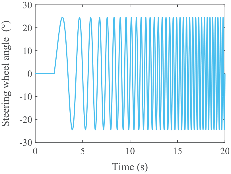
The signal of swept-sine steering input.
Evaluation index
Evaluation index
Evaluation index
Simulation of the impact of the change in position of trailing arm bushing on evaluation indexes
The response surface plot of evaluation index

Results of swept-sine steering input simulation: (a) response surface plot of evaluation index
The Figure 6(d) presents the response surface plot of evaluation index
The response surface plot of evaluation index
Position design of trailing arm bushing
Based on the analysis above, it is evident that not all evaluation indexes of vehicle transient performances are optimized under the same bushing installation position. To achieve a more rational position design of the bushing, this study converts the design problem of bushing position into a multi-objective optimization problem. The evaluation indexes of the transient performances are utilized as objective functions, and angles
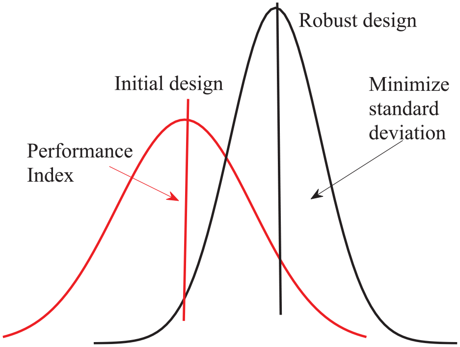
In the context of optimization research, it can be broadly categorized into deterministic optimization and non-deterministic optimization. Deterministic optimization assumes all design variables are deterministic parameters, and optimization does not consider the effects of variations in design variables on the objective function. In practical engineering problems, design parameters often exhibit uncertainty that cannot be avoided. 1 Designing based on deterministic assumptions may result in design outcomes that do not meet expectations. Therefore, it is becoming increasingly important to account for uncertainties during the optimization process. Robust optimization design, as an approach to addressing uncertainties, differs from deterministic optimization as illustrated in Figure 7. 18
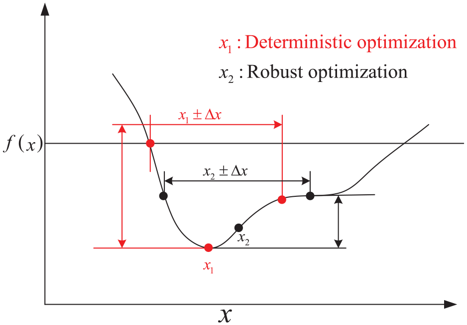
Deterministic and robust optimization.
For the actual position design of trailing arm bushing, there may be errors in the design and manufacture of the bushings, which will cause the performance indexes of the transient performances of the vehicle to deviate. This will result in the designed position of bushing not meeting the performance requirements of the vehicle. When design the position, it is often desirable that the position of bushing is designed in such a way that it satisfies the optimal design while minimizing fluctuations in the optimization objective function caused by uncertainties, resulting in a more robust vehicle performance. Therefore, this paper will carry out robust optimization considering uncertainties on the basis of deterministic optimization.
Mathematical expressions for multi-objective deterministic optimization
The evaluation index

Mathematical expressions for multi-objective robust optimization
This study employs a probabilistic model to characterize the uncertainties associated with the parameters, assuming that the uncertain variables follow a normal distribution.
Figure 8 illustrates the concept of probabilistic robust optimization. The mean
Probabilistic robust optimization.
Therefore, by combining equation (19), a mathematical expression for robust multi-objective optimization can be formulated as:

Multi-objective optimization algorithm
In multi-objective optimization problems, it is often necessary to make trade-offs among different criteria since the optimization objectives may have conflicting requirements. Therefore, it is crucial to choose an appropriate multi-objective optimization algorithm for multi-objective optimization to achieve optimal results. The genetic algorithm is a population-based search algorithm that emulates the process of biological evolution, continuously exploring and comparing candidate solutions in search of optimal solutions while discarding inferior ones. In a standard genetic algorithm, the individuals from the last generation are discarded during the iteration process. As a well-established modern genetic algorithm, NSGA-II employs an elite preservation strategy that better retains elite individuals, addressing the issue of discarding individuals from the last generation as in standard genetic algorithms. Furthermore, this algorithm reduces the computational complexity from
Figure 9(a) illustrates the concept of dominance in the algorithm, where if the optimization objectives are to minimize both

(a) Diagram illustration of domination and (b) diagram illustrating of crowding distance.
Figure 9(b) presents a crowding distance diagram for an optimization problem with two objectives. The sum of the distances from
Table 3 shows the main parameters of the algorithm in this paper.
Main parameters of NSGA-II algorithm.

Construction of approximate model
When considering the uncertainties, a large number of computations are required in the optimization process to obtain the mean and standard deviation of the optimization objectives. To enhance optimization efficiency, this study proposes the use of approximate model as substitutes for simulation model in multi-objective optimization. The approximate model is employed to approximate the mapping relationship between optimization variables and objective functions. It is described as shown in equation (21).

Where:
The Radial Basis Function (RBF) neural network model is a type of three-layer feedforward neural network structure. The layer that receives input signals is referred to as the input layer, while the layer that produces output signals is called the output layer.
20
The layer that does not have direct connections with the input or output is known as the hidden layer or intermediate layer. The transformation from the input layer to the hidden layer involves a fixed and nonlinear mapping that directly maps the input vector to a new space. The model takes the Euclidean distance between the test points and the sample points as the independent variable, assuming
Therefore, this paper will use the RBF neural network model to construct the mapping relationship between the objective function and the design variables, and its establishment process is shown in Figure 10.

Flowchart of RBF approximation model building.
Firstly, a multi-body dynamics model is used for simulation calculations to obtain the sample data required for constructing the approximate model. Secondly, the obtained data is used for sample training to build the RBF model. Finally, the accuracy of the constructed RBF model is verified. If the accuracy of the model satisfies the design criteria, it indicates that the RBF model can replace the actual multi-body dynamics simulation model. If the accuracy does not meet the requirements, the sample size needs to be increased until the accuracy meets the design requirements.
The accuracy of the approximation model has a direct impact on the feasibility and reasonableness of the solution obtained from the optimization. In general, Root Mean Square Error (RMSE), Coefficient of Determination (R2), and Maximum Absolute Error (MAE) are commonly used as error analysis indexes to evaluate the accuracy of approximate model. The global accuracy of the model can be assessed by the RMSE and the R2. The local accuracy of the model can be evaluated by the MAE. RMSE, R2, and MAE can be calculated by equation (22) 21 :

Where:
For the evaluation of the accuracy of the approximation model, the smaller the value of
Figure 11 shows the fitting results of the RBF model established in this paper. From the figure, it indicates that the predicted values of each evaluation index are closer to the actual values. The predicted trend line of each index basically shows 45°. The accuracy evaluation indexes of the approximate model are shown in Table 4. From the table, it indicates that the output error of the model trained by the RBF neural network is smaller and the accuracy is higher. Therefore, the established approximate model can be used for the optimization study in this paper.

Accuracy verification: (a)
The accuracy of RBF model.

Discussion of optimization results
The projection of the Pareto front for each evaluation index obtained by deterministic and robust optimization is shown in Figure 12. As can be seen in the figures, the trends in the distribution of the Pareto front obtained from deterministic and robust optimization are more similar. Compared to deterministic optimization, robust optimization yields more Pareto solutions for evaluation indexes, as the objective function in robust optimization considers not only the means but also the standard deviations of the indexes.

Pareto front project of index: (a)
In Figure 12, Solution 1 and Solution 2 represent the relative optimal solutions obtained from deterministic optimization and robust optimization, respectively. The design variables under the relative optimal solutions are shown in Table 5.
Design variables before and after optimization.

The design variables values obtained from the relative optimal solutions of deterministic optimization and robust optimization are re-inputted into the vehicle simulation model for simulation, and the optimization results are validated. Figure 13 shows the corresponding curves obtained from the simulation. The evaluation indexes before and after optimization are shown in Table 6.

Deterministic versus robust optimization: (a) yaw rate gain, (b) delay time, and (c) roll angle gain.
The evaluation index before and after optimization.

Figure 13(a) shows the yaw rate gain for two types of optimization. It can be observed from the figure that the yaw rate gain under deterministic optimization is smaller than that under robust optimization. Combined with the results in Table, it can be concluded that the evaluation indexes
Figure 13(b) shows the delay time of lateral acceleration under two types of optimizations. It can be observed from the graph that the absolute value of delay time under deterministic optimization is smaller than that under robust optimization. Based on the values in Table 6, it can be observed that the evaluation criteria
Figure 13(c) shows the roll angle gain for the two optimizations. It can be observed from the graph that the roll angle gain under robust optimization is smaller than that under deterministic optimization. From the Table 6, it can also be observed that the evaluation index
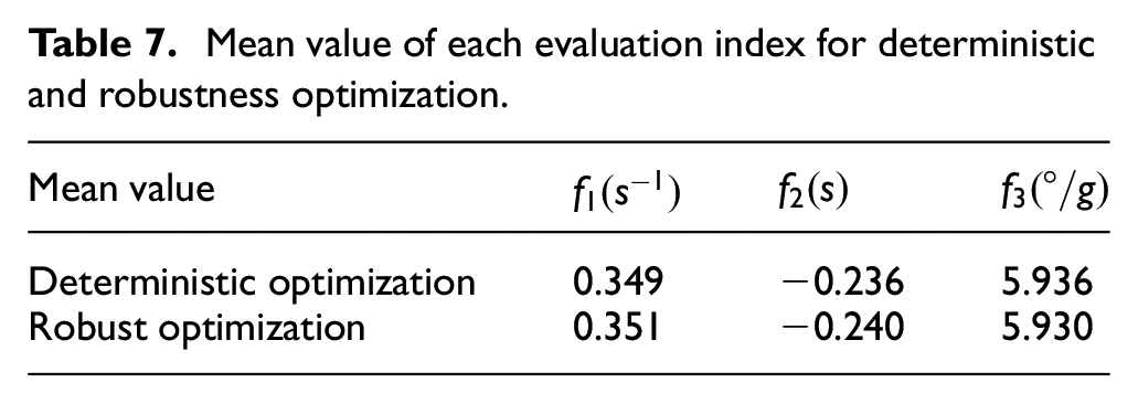
In actual suspension manufacturing, there are inevitably numerous uncertainties that can result in fluctuations in the objective function. This study conducted robustness analysis on the transient performance indexes of the vehicle under two optimized bushing positions to assess the sensitivity of the evaluation criteria to the influence of uncertainties. In order to investigate the sensitivity of each performance index of the vehicle to the influence of uncertainties under the two optimization results, a robustness analysis of the transient performance indexes of the vehicle under the two optimized bushing position solutions is carried out. Monte Carlo simulation is a mathematical statistical method based on probabilistic statistical theory, which has the advantages of simple structure of the computational procedure, adaptability and no need to consider the dimensionality of the problem. Therefore, it will be used in this paper to perform robustness analysis of optimization solutions. In terms of sampling method, this paper uses the descriptive sampling method of Monte Carlo simulation for 2000 samples as it is more computationally efficient. The probability distributions of each objective function under the obtained deterministic and robust optimization results are shown in Figure 14. The mean value and standard deviation of each optimization objective is shown in Tables 7 and 8, respectively.

Probability distributions for the two solutions: (a)
Mean value of each evaluation index for deterministic and robustness optimization.
Standard deviation of each evaluation index for deterministic and robustness optimization.

Based on Table 7, it can be observed that the bushing position determined through deterministic optimization resulted in smaller mean of the evaluation index
As can be seen in Table 8, compared to deterministic optimization, the standard deviation of each evaluation indexes under robust optimization is smaller. Therefore, for evaluation indexes
Conclusions
This paper investigates the impact of the position of the trailing arm bushing for torsion beam on vehicle transient handling performances through a combination of theoretical analysis and simulation. Considering the uncertainties and transient performance of the vehicle, the design of the bushing position is converted to multi-objective optimization. The mapping relationship between the bushing position and the evaluation index of transient performances is approximated by radial basis function (RBF) neural network model. Finally, the NSGA-II intelligent algorithm is employed to solve the optimization problem. Based on the multibody dynamics vehicle model proposed in this study, the following conclusions can be deduced:
(1) The variation of the bushing position of trailing arm mainly influence dynamic response of the vehicle at low handling frequencies. When the bushing is installed at position
(2) The RBF neural network model can be effectively used for the position design of the bushing in the trailing arm for torsion beam.
(3) When not taking into account uncertainties, the bushing position determined by deterministic multi-objective optimization results in a better handling performance. When considering the uncertainties, the bushing position determined by robust multi-objective optimization results in a vehicle with stronger anti-roll performance, and the fluctuations in evaluation indexes are smaller, indicating stronger robustness and better suitability for practical applications when design variables change.
Footnotes
Appendix 1
Handling Editor: Chenhui Liang
Declaration of conflicting interests
The author(s) declared no potential conflicts of interest with respect to the research, authorship, and/or publication of this article.
Funding
The author(s) disclosed receipt of the following financial support for the research, authorship, and/or publication of this article: This work was supported by National Natural Science Foundation of China (NSFC) (No. 51965026). The authors are greatly appreciated for the financial support.