
Abstract
To meet the requirements of high flexibility, high stiffness, and large working range of space debris cleaning technology, a foldable composite space capture mechanism is proposed based on the finite screw theory in this paper. The degree of freedom of the mechanism is analyzed by using the screw theory and its degree of freedom is obtained. The closed-loop vector method and DH method are used to analyze the kinematics of the mechanism, and the position solution of the mechanism is derived. The analytical expressions of velocity and acceleration solutions are obtained by differential calculation. According to the analysis of numerical example, the kinematic model of the mechanism is built in the simulation environment, and the simulation experiment is carried out for the motion trajectory of the mechanism. The correctness of theoretical analysis solution and method is proved by contrasting and analyzing motion trajectory, and it is verified that the space capture mechanism uses the foldable property to form large workspace to complete the capture of the target.
Introduction
With the development of aerospace industry, the amount of discarded space debris in space is increasing gradually. The space debris has the characteristics of irregular shape, excessive inertia, and unknown motion parameters, will cause impact threat to spacecraft in use. Therefore, it is very difficult and risky to capture space debris on orbit. 1 The research and development of a space capture mechanism with low accuracy, high stiffness, high load capacity, and large workspace has important scientific significance and research value for enriching and improving space debris cleaning technology and improving innovative development in the aerospace field.
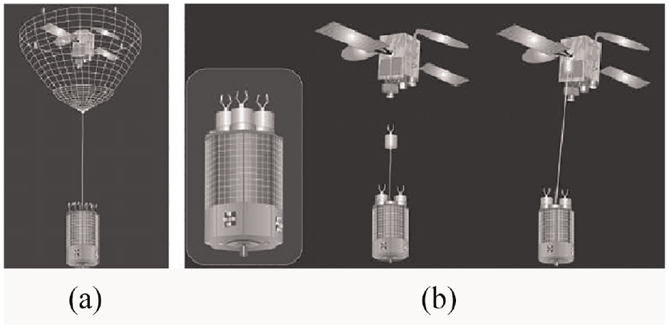
In view of this phenomenon, domestic and foreign scholars have carried out in-depth research on space debris cleaning technology. At present, there are three kinds of space debris cleaning technologies: rigid capture by space manipulator2–4 (as shown in Figure 1), telescopic rod to capture engine nozzle 5 (as shown in Figure 2), and flexible capture by mechanisms such as flying nets and flying claws 6 (as shown in Figure 3). Most of the manipulators used for capturing are series manipulators, which have high dexterity and large workspace, but weak load capacity. In the work, the target will fail to be captured due to chattering or deformation. The parallel manipulator has high stiffness and strong load capacity, but small workspace. Using telescopic rod to capture engine nozzle requires high capture accuracy and difficult operation. Using flying net or flying claw capture mechanism has low stiffness, unable to carry out other operations on the target.

European space manipulator ERA.

SMART-OLEV.
ROGER capture system: (a) fly net type and (b) fly claw type.
Aiming at the existing problems of the current space capture mechanism, this paper proposes a foldable composite space capture mechanism based on a single ring folding mechanism and a translation and rotation coupling mechanism. The single ring folding mechanism is a closed-loop link system composed of the link and the motion joint between the link, which has the advantages of large expansion ratio, high stiffness, and good flexibility, etc., and has been used in truss deployable antenna and other fields.7,8 The translation and rotation coupling mechanism has large workspace, which can quickly locate the moving target to be captured and realize detumbling operation, so that its attitude and speed are synchronized with the target to be captured. The combined space capture mechanism of the two is easier to capture the target and can eliminate the impact and interference of space debris in the space station. Yao et al. 9 proposed a polyhedral network space capture mechanism based on three-RRS parallel mechanism. Liu et al. 10 completed the clamping and pushing of the docking target based on the scaling and flipping characteristics of the Bricard mechanism. However, the above research ignored the kinematic coupling between the composite mechanisms and only analyze the simplified model. Because of the variability of its structure and the complexity of its design problems, the analysis and research of this kind of mechanism has been a great challenge for a long time.
In view of the shortcomings of the current space debris cleaning technology, the configuration design and kinematics analysis of the foldable composite space capture mechanism are studied in this paper. The kinematic decoupling is realized by constructing the internal relation of the single ring folding mechanism and the translation and rotation coupling mechanism, to ensure that the composite space capture mechanism can complete the complex tasks such as detumbling operation and in-orbit maintenance. The specific research contents of this paper are as follows:
In section “Configuration design,” combined with the configuration characteristics of the space capture mechanism, the configuration characteristics of the composite mechanism are obtained by using the finite screw theory. In section “Degree of freedom analysis,” under the topological configuration of the mechanism, the screw theory is used to analyze the degree of freedom of the mechanism, to ensure that the foldable composite space capture mechanism can achieve the capture task. In section “Kinematic analysis,” the DH method is used to analyze the position solution of 8R mechanism. And then the closed-loop vector method is used to analyze the position solution of PRS-PSS-PRS-PSS mechanism. Finally, the velocity and acceleration solutions of the mechanism are derived by differential calculation. In section “Numerical examples,” based on the kinematics analysis of the mechanism, the numerical example analysis is carried out. By comparing the motion trajectory obtained by MATLAB software programming and SolidWorks software simulation, it is verified that the measured values are consistent with the theoretical values. And then the correctness and feasibility of the theoretical analysis method is verified.
Configuration design
Space debris mainly includes discarded satellites and rocket fragments, which are collectively referred to as space non-cooperative objects. Due to its large spin, 11 it is convenient to capture it quickly and comprehensively. A foldable composite space capture mechanism is proposed in this paper, which the translation and rotation coupling mechanism is the main part and the single ring folding mechanism is the moving platform. The space capture mechanism should be defined with four degrees of freedom.
According to the different types of freedom, the 4-DOF (degree of freedom) parallel mechanism can be generally divided into 1T3R, 2T2R and 3T1R, where T represents the translation DOF, and R represents the rotation DOF. According to the shortcomings of the existing space capture mechanism, it is defined that the space capture mechanism should have 2T2R. Firstly, the configuration synthesis of the parallel mechanism is carried out. At present, some scholars have conducted configuration synthesis research on the 4-DOF parallel mechanism.12,13 In this paper, based on the results of Xie’s configuration synthesis of the 2T2Rmechanism, 14 as shown in Table 1, the configuration design of the space capture mechanism is completed using the finite screw theory.
2T2Rmechanism configuration synthesis results.

Three limb configurations can be obtained by reasonable arrangement of all joints, as shown in Figure 4.
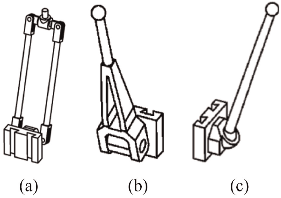
Limb configuration: (a) PR(Pa)RR, (b) PRS, and (c) PSS.
Based on the finite screw theory, 15 the PR(Pa)RR limb configuration can be expressed as

where, the symbol “Δ” represents the screw triangle product,
The PRS limb configuration can be expressed as

The PSS limb configuration can be expressed as

After the available limb configurations are obtained, the overall configuration of the mechanism is obtained through assembly conditions and actuation arrangement. Three configurations are listed here, as shown in Figure 5.

Mechanism configuration: (a) PRS-PSS-PRS-PSS, (b) PRS-PRPaRR-2PSS, and (c) PRU-3PSS.
According to the application scenario, the configuration of PRS-PSS-PRS-PSS mechanism is selected, and its configuration characterization is shown in formula (4). Because its limbs are symmetrically distributed and the configuration is regular, and it can quickly locate the target to be captured. Thus, it is the main part of the foldable composite space capture mechanism in this paper.

The rotation and workspace of the parallel mechanism are limited. To achieve flexible capture, the moving platform can adjust itself according to the target shape to find the most easily captured side of the target for capture. Therefore, the moving platform is a single ring folding mechanism, which has the function of folding and closing to pull the target inward and cooperate with the limb to clamp the target, and thus prevent the target from escaping. At present, the classic single ring folding mechanism includes four-links mechanism-Bennett mechanism, 16 six-links mechanism-Bricard mechanism, 17 and eight-links mechanism-8R mechanism. 18
The motion process of three single ring folding mechanisms is shown in Figures 6 to 8. Through comparative analysis, the touchpoints of Bennett mechanism and Bricard mechanism are 2, and the touchpoints of 8R mechanism are 4. Considering the symmetry of the folding mechanism, the 8R mechanism is selected as the single ring folding mechanism of the moving platform.

Bennett mechanism: (a) fully expanded state, (b) intermediate state, and (c) fully folded state.

Bricard mechanism: (a) fully expanded state, (b) intermediate state, and (c) fully folded state.

8R mechanism: (a) fully expanded state, (b) intermediate state, and (c) fully folded state.
Based on the above analysis, this paper proposes a foldable composite space capture mechanism with PRS-PSS-PRS-PSS mechanism as the main part and 8R mechanism as the moving platform, as shown in Figure 9. The mechanism can meet the requirements of high flexibility, high stiffness, and large workspace for space debris cleaning technology.

8R& PRS-PSS-PRS-PSS mechanism schematic diagram.
Degree of freedom analysis
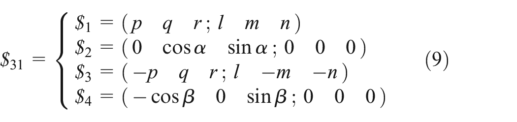
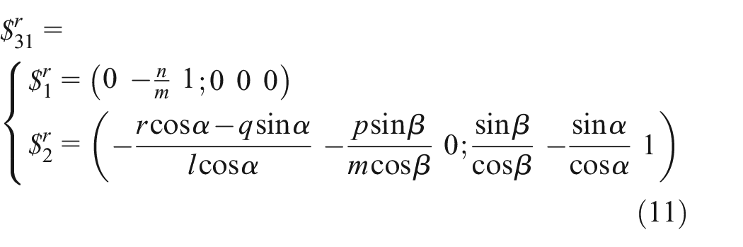
As shown in Figure 10, PRS-PSS-PRS-PSS mechanism is composed of two PSS limbs and two PRS limbs. The PSS limb is shown in Figure 11, and the screw system of the limb can be expressed as


PRS-PSS-PRS-PSS mechanism schematic diagram..

Screw analysis of PSS limb.
where,
The PRS limb is shown in Figure 12, and the screw system of the limb can be expressed as

where,


Screw analysis of PRS limb.
According to the screw analysis, the mechanism has two reciprocal screws, which can realize the 4-DOF motion with two directions of rotation and two directions of translation. Using the modified Grübler-Kutzbach formula, 19 it can be obtained

where,
As shown in Figure 13, the 8R mechanism is a closed ring composed of eight links and eight rotational joints, and the spatial angle of the axis of each rotational joint is 45°. In the general position, the mechanism has two planes of symmetry

8R mechanism schematic diagram.
The 8R mechanism can be regarded as a parallel mechanism composed of two RRRR limbs. Let
The screw system of the second limb can be expressed as

By calculating the reciprocal screw of the two limbs respectively, it can be obtained

Finally, the 8R mechanism has four reciprocal screws, so the degree of freedom of the mechanism is 2. Using the modified G-K formula can be obtained

where,
Based on the above analysis, according to the mutual constraints between the limbs of the 8R mechanism and the PRS-PSS-PRS-PSS mechanism, the 8R& PRS-PSS-PRS-PSS composite space capture mechanism can realize the 4-DOF motion of two-direction rotation and two-direction translation. It can meet the requirements of quick location, detumbling operation, synchronous capture, large workspace, and high capture efficiency.
Kinematic analysis
Kinematics analysis is the premise of the research mechanism, and its main content is to analyze the position, speed, acceleration, and other aspects of the mechanism. The key to the kinematic analysis of the composite space capture mechanism lies in the kinematic transformation between the 8R&PRS-PSS-PRS-PSS mechanism and the PRS-PSS-PRS-PSS mechanism.
In this section, the DH method is firstly used to establish the link coordinate system at each joint of the 8R mechanism, and then the position analysis of PRS-PSS-PRS-PSS mechanism is carried out through the closed-loop vector method to reveal the relationship between the actuation parameters of the mechanism and the end pose. Finally, the velocity and acceleration solutions of the mechanism are derived through differential calculation to complete the kinematic analysis of the mechanism. As shown in Figure 14.

Kinematic analysis flow diagram.
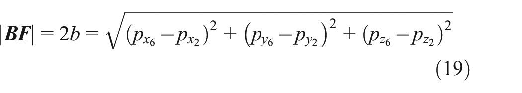
When 8R&PRS-PSS-PRS-PSS mechanism performs the capture task, any captured object can be converted into an envelope sphere. Therefore, after the outer contour spherical radius of the captured object is known, the length of the opposite side BF and DH of the 8R mechanism, can be determined. The positions of the end points

xOy cross section illustration.
Position analysis of 8R mechanism
As shown in Figure 16, the link coordinate system is established at each rotational joint of the mechanism, and the coordinate axis

8R mechanism structure diagram.
The coordinate system is established according to the DH method, and the corresponding parameters of the connecting link are shown in Table 2.
DH parameters of 8R mechanism.

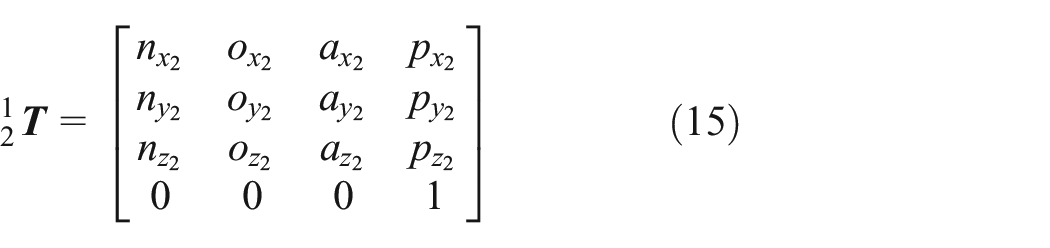
For the established coordinate system, the general formula of transformation matrix from the

Where,
It is known that the 8R mechanism has two degrees of freedom, the actuated angle
According to the above angle relationship, the corresponding transformation matrix can be written as


The coordinates of connection points B, D, F, and H of 8R mechanism and PRS-PSS-PRS-PSS mechanism in the reference coordinate system
Therefore, the relationship between moving platform dimensions

Inverse position analysis of PRS-PSS-PRS-PSS mechanism
As shown in Figure 17, a fixed coordinate system

PRS-PSS-PRS-PSS mechanism structure diagram.
For the PRS-PSS-PRS-PSS mechanism, any vector

where,

where,
Take one PSS limb as the research object, as shown in Figure 18. Given


PSS limb position analysis.
Given that

Since


If there is but one unknown

Similarly, the actuated distance of the translational joint of another PSS limb can be expressed as

Take one PRS limb as the research object, as shown in Figure 19. Given


PRS limb position analysis.
Given that

Since


If there is but one unknown

Similarly, the actuated distance of the translational joint of another PRS limb can be expressed as

Velocity and acceleration analysis
Based on the above position analysis, the vector relationship between the limbs can be obtained according to Figure 20(a) and (b), and the closed-loop vector equation can be expressed as


Velocity analysis of the PRS-PSS-PRS-PSS mechanism: (a)
If the unit vector of

Formula (35) through differential calculation can be obtained as

where,
To facilitate calculation, multiply the left and right ends of formula (36) by

Since the direction of

If the actuation equation of the actuated distance
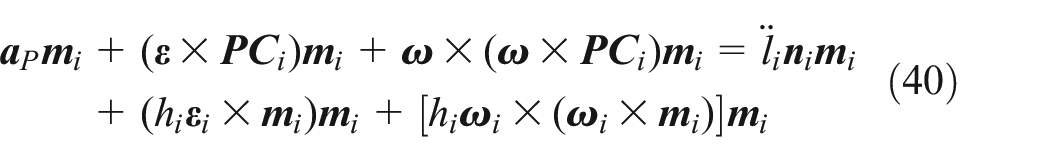
Formula (36) through differential calculation can be obtained as

where,
To facilitate calculation, multiply the left and right ends of formula (39) by
Since the direction of

If the actuation equation of the actuated distance
Numerical examples
The 8R&PRS-PSS-PRS-PSS mechanism analysis has been converted to the PRS-PSS-PRS-PSS mechanism analysis in Section “Degree of freedom analysis.” And the PRS-PSS-PRS-PSS mechanism is the main body of the foldable composite space capture mechanism, so the simulation of its motion analysis is carried out to verify the correctness and feasibility of its theoretical derivation. Fixed platform radius

Motion trajectory of the center point of the moving platform.
The position vector

The software MATLAB and SolidWorks are used to analyze the motion laws in the above process, and the results are shown in Figures 22 and 23. In Figure 22, the four lines are the change curves of actuated parameter of limb 1, 2, 3, and 4 obtained by MATLAB analysis respectively. In Figure 23, the curves represented by

The change curves of actuated parameter.

Position change of point P in the fixed coordinate system.
Conclusion
To solve the existing acquisition problems of space debris cleaning technology, a composite space capture mechanism with variable platform is proposed in this paper, which has important scientific significance and research value for enriching and improving space debris cleaning technology and improving innovative development in the aerospace field. The main conclusions are as follows
(1) Based on the finite screw theory, the configuration design of the 8R&PRS-PSS-PRS-PSS composite space capture mechanism is completed. The mechanism has the advantages of high flexibility, high stiffness, and large spread to harvest ratio.
(2) The screw theory is used to complete the analysis of the degree of freedom of the mechanism. The DH method and the closed-loop vector method are used to solve the analytical expression of the position of the 8R mechanism and PRS-PSS-PRS-PSS mechanism. The kinematic theory analysis of the mechanism is completed through the differential operation.
(3) Through transforming 8R&PRS-PSS-PRS-PSS mechanism analysis into PRS-PSS-PRS-PSS mechanism analysis. The correctness and feasibility of the theoretical analysis method of PRS-PSS-PRS-PSS mechanism are verified by numerical examples.
(4) In the future research, according to the application scenarios, the shape and size of the captured target should be comprehensively considered, and the size and section parameters of the mechanism should be optimized to promote its engineering application scenarios.
Footnotes
Handling Editor: Chenhui Liang
Declaration of conflicting interests
The author(s) declared no potential conflicts of interest with respect to the research, authorship, and/or publication of this article.
Funding
The author(s) disclosed receipt of the following financial support for the research, authorship, and/or publication of this article: This work was supported in part by the National Natural Science Foundation of China under Grant 51905378, in part by the Tianjin Science and Technology Plan Project 22JCYBJC01670 and Project 21JCZDJC00820, in part by the Tianjin University Science and Technology Development Fund Project 2020KJ105, in part by the Scientific Research Foundation of Tianjin University of Technology and Education under Grant KYQD1901, in part by the Natural Science Foundation of Tianjin under Grant 20JCQNJC00360, and in part by the Tianjin Enterprise Science and Technology Commissioner Project 20YDTPJC00450.
Data availability statement
Data are available from the authors on request.