
Abstract
Diesel generator sets are commonly used as power sources in transportation due to their versatility and cost-effectiveness. During the shutdown process, the diesel engine’s cylinder compression pressure would cause forced vibration in the driveline system through the crank linkage mechanism, resulting in unsteady loads that pose a threat to the bearing life. To address this issue, a coupling forward design method is proposed that takes into account the impact of unsteady loads on bearing life. An experiment was conducted on a 16V280 diesel generator set shutdown process, and a driveline dynamic model was established. The cumulative damage value that connects unsteady loads and bearing life was introduced to quantify the effect of unsteady loads on the bearing life during the shutdown process. The unsteady loads included torque fluctuation and collision forces. The results showed that reducing the driveline key gap and increasing the coupling stiffness can decrease the combined load on bearings and improve bearing life. A large stiffness coupling was designed to achieve shutdown smoothness and a 43.19% reduction in bearing life damage, confirming the design method’s feasibility concerning bearing life.
Introduction
A diesel generator set is a compact and portable power system that finds widespread application in various industries, including railway vehicles, ships, and other fields. 1 During diesel engine shutdown, the combination of unbalanced cylinder compression pressure and reciprocating inertia forces from the piston results in speed fluctuations. 2 Excitations from the diesel engine are transmitted to the generator through an elastic coupling, where it is common to change stiffness and damping parameters to adjust the amplitude and frequency for better vibration damping. However, this method would generate strong resonance and amplified torque fluctuations when drivelines pass through the critical speed during startup or shutdown processes.3–9 Moreover, the coupling in the driveline is commonly connected to the generator shaft through a key, which compensates for deviations due to inaccurate manufacturing and installation, deformation, and thermal expansion during operation. The presence of the key and fit tolerance gap also leads to continuous collision accompanied by torque fluctuation in the transmission process.10,11 The complex load during the shutdown, which includes amplified torque fluctuations and collision forces, significantly reduces bearing life. A novel design approach is needed to address this issue.
Couplings in the driveline were selected and designed to meet the torque transmission requirements and to achieve vibration damping by adjusting their stiffness and damping parameters to avoid operating at critical speeds. 12 The main parameters of the driveline system were determined, then the primary vibration modes were analyzed by a dynamic model and the stress-strain characteristics of the shaft system were evaluated. 13 However, the design process did not account for the load on the bearing at critical speed, which has a significant impact on reducing bearing life. Current research on bearing life primarily focuses on data-driven life prediction14,15 and prediction based on fatigue theory. The former studies belong to online fault diagnosis and are not suitable for the forward design of the driveline system. The latter studies, based on the Lundberg-Palmgren (L-P) life model, 16 employ a classical fatigue life prediction theory that uses metal fatigue probabilities following a Weibull distribution. To account for the impact of lubrication characteristics on frictional forces and reliability, a correction method with a correction factor for bearing fatigue life was proposed.17,18 This method has been successfully applied to evaluate and calculate bearing life for specific loads at different speeds in engineering practice. 19 However, this method is only suitable for predicting bearing life under steady-state conditions. Further research is needed to develop a method that can quantify bearing life, especially when considering the impact of the shutdown process.
The shutdown process of diesel generator sets has the following characteristics: (a) The shutdown process has torque fluctuations and is a forced vibration process. (b) The shutdown process at critical speed would amplify the torque fluctuations and produce collisions. The bearing life is influenced by the load, with harsh load conditions having the potential to significantly reduce its longevity. The design of coupling parameters plays a crucial role in determining the load on the bearing during critical speeds, and as such, must be considered to ensure the longevity of the bearing. To address this design challenge, the following steps must be undertaken: (1) To establish a correlation between the driveline system dynamic model and bearing loads. (2) To conduct a quantitative study on the evaluation method of bearing life during the shutdown process. (3) To develop a coupling design method for diesel generator sets that take into account the bearing life.
In this study, a systematic method for evaluating the bearing life of a diesel generator set during its shutdown process is presented. The study is organized as follows: firstly, a diesel generator set shutdown process was used as an experimental case to analyze the significance of unsteady vibration generated during the shutdown process on bearing life and the driveline dynamic model was constructed. Then, the correlation between bearing loads and the established driveline dynamic model was established. After that, an evaluation method for quantifying the bearing life was proposed during the shutdown process. Finally, a new coupling design is executed to validate the feasibility of considering bearing life in the coupling design method.
Problem formulation
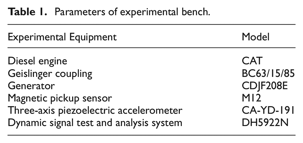
During the shutdown process of the diesel generator set, the diesel engine’s cylinder compression pressure would drive the flywheel and the coupling to rotate through the crank linkage mechanism. The generator input shaft was connected to the driven part of the coupling through a flat key, and the presence of a key gap could lead to collisions during operation. This study utilized a shutdown process of a 16V280 diesel generator set as a case study, and a schematic representation of the measurement points and power transmission is depicted in Figure 1. A magnetoelectric sensor was positioned on the flywheel of the diesel engine to monitor the torsional vibration behavior of the transmission shaft, and a three-axis piezoelectric accelerometer was placed on the generator’s bearing seat to measure the vibration response synchronously. The parameters of the components used in the experimental bench are presented in Table 1.
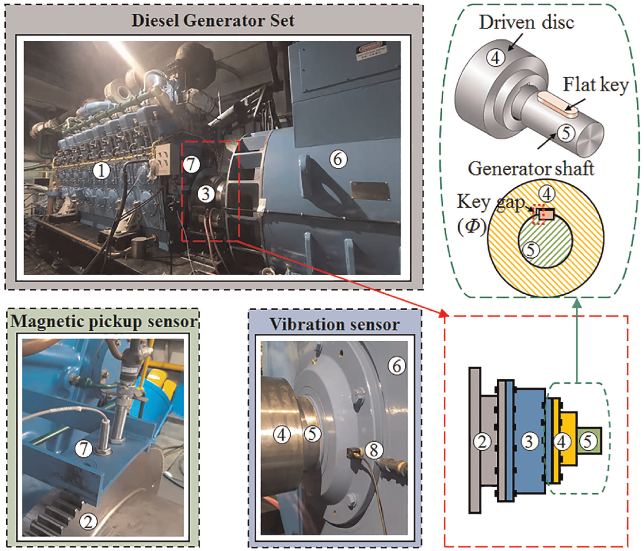
Layout diagram of measuring points. ① 16V280 Diesel engine ② Flywheel and driving part of coupling ③ Geislinger coupling ④ Coupling driven disc ⑤ Generator shaft ⑥ Generator ⑦ Magnetic pickup sensor ⑧ Vibration sensor.
Parameters of experimental bench.
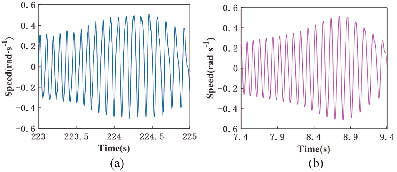
The Dynamic Signal Test and Analysis System was utilized to analyze the rotational speed signal of the flywheel and the vibration signal on the bearing seat, as shown in Figure 2. The data depicted in Figure 2(a) showcased that during the shutdown process, torque fluctuations were magnified as the critical speed was crossed, leading to substantial fluctuations in rotational speed. The vibration signal on the bearing seat simultaneously produced a larger amplitude, as shown in Figure 2(b), indicating that the driveline amplified torque fluctuations and generated collisions as it passed through the natural frequency of the driveline. The excitation was transmitted from the generator input shaft to the bearing seat, resulting in the stimulation of synchronous vibration. The unfavorable load on the bearing during the shutdown process is expected to reduce its service life.

Comparison of test signals: (a) torsional vibration speed fluctuation and (b) vertical vibration Acceleration.
Bearing life analysis method during shutdown processes
The experiments illustrated that when the driveline system passed through the critical speed during the shutdown process, significant vibration was generated in the bearing seat due to the poor load conditions on the bearing. This highlights the importance of considering the impact of the shutdown process on the bearing life. This section endeavors to quantitatively evaluate the bearing life during a shutdown process by establishing a correlation between the driveline and bearing loads, with the ultimate goal of predicting the impact of the shutdown process on bearing life.
Modeling the driveline system
The driveline dynamic model should represent the main moment of inertia, the stiffness and damping of the connection between the main components and the main characteristics of the gap in the driveline system. 7 Therefore, the article adopts four assumptions: (a) Centralized inertia assumptions: The model assumes that components with larger and more concentrated inertia are considered as inelastic inertia components, while components with smaller and dispersed inertia are regarded as inertia-free components. In the diesel engine shaft system, the moment of inertia of the moving components, including the piston-rod, and crankshaft, in each cylinder is simplified as the concentrated inertia at the center of each crank. Following the principle of energy equivalence, the moment of inertia of the driveline model includes the diesel engine shaft system with flywheel and driving part of the coupling (J1), driven part of the coupling (J2), and generator rotor shaft system (J3). (b) Stiffness linearization assumption: The assumption of the stiffness linearization is that the deformation of elastic elements is small, and nonlinear characteristics of materials and geometric nonlinearities are neglected. Therefore, all elastic elements are treated as linear. The dynamic stiffness of the coupling is simplified as kdyn. (c) Damping linearization assumption: In a vibration system, the vibration velocity decreases gradually due to external effects on energy dissipation by damping elements, such as lubricating oil resistance, and inter-structural friction. It is approximated that this damping force is proportional to the velocity, considering the viscosity of the medium. The dynamic damping of the coupling is simplified as cdyn, and the damping of the resistance moment on the diesel engine’s crankshaft system is simplified as ct. (d) Newtonian collision model assumption: It is generally believed that only elastic deformation occurs during the collision process, while plastic deformation can be ignored. 5 Therefore, the Newtonian collision model is used, neglecting energy losses. The process of transmitting force through the collision of the flat key in the driveline system is expressed by using the Newtonian collision model.
In driveline system, the flat key is mounted on the generator shaft with a radius r. The torque fluctuation is transmitted by the transmission force Fc. According to Newton’s second law of motion, a 3-DOF driveline system dynamic model could be constructed to express main characteristics of dynamics at time t during the shutdown process. Schematic diagram of the 3-DOF driveline model is shown in Figure 3, and the dynamic model is represented as
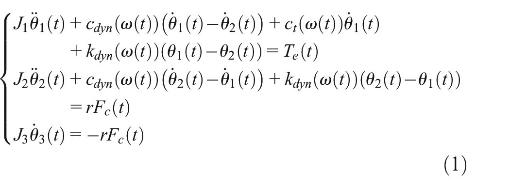
where θ1, θ2, and θ3 are denoted as the angular displacement of three different inertias. The input fluctuation torque Te is considered the main excitation source, with only the 4.0 harmonic and the 8.0 harmonic being taken into account, and the generator running resistance torque, The generator running resistance torque Td is also considered. A detailed presentation of Te and Td could be found in the literature.
8
The tested 16V280 diesel generator set was simplified by three moments of inertia, J1 = 177.65, J2 = 2.26, J3 = 602.60 kg/m2, and a radius of r = 100 mm. The flywheel resistance damping coefficient ct plays a crucial role in providing the driveline system with a resistance moment. The resistance moment and the excitation act together on the inertia J1 in the shutdown process. The deceleration slope

where the characteristic frequency of the coupling ω0 was determined to be 290 rad/s.

Schematic diagram of the 3-DOF model of driveline.
The transmission force, Fc, acting on the flat key could be expressed as

where the flat key gap Φ was determined to be 0.28 mm. The viscous drag force generated by the lubricating oil in the gap of the key, damping coefficient is c = 100 N·m·s/rad, collision stiffness is kg = 1,000,000 M·N·m/rad. 20
The relationship between the transmission force Fc and the gap Φ obtained from equation (2) could not be used directly for numerical calculation in the time domain. It is known that the numerical time integration is time-consuming and may encounter numerical ill-conditioning and “stiffness” issues due to the extremely strong collision nonlinearity. 21 To mitigate these issues, a hyperbolic tangent function, y = tanh(σ·δ), is introduced to smooth the nonlinear collision process in the original model. 21 The smoothing factor (σ) is chosen to be 1000 in this study. The transmission force generated by the key could be expressed

A reasonable model should be able to reflect accurately depict the fluctuations in amplitude and frequency when passing through the critical speed. 3 The shutdown process has taken 12 s and the fluctuation speed was amplified in the test. The classic fourth-order Runge-Kutta method 5 could be adopted to calculate the dynamic response of the control equation (1). The Detrended Fluctuation Analysis (DFA) 22 was applied to analyze the deceleration curve depicted in Figure 2(a) for both the test and the 3-DOF model. The fluctuation values at resonance for the test and simulation are displayed in Figure 4(a) and (b) respectively. As depicted in Figure 4, the number of fluctuations generated at resonance is equivalent between the test and the simulation. The comparison between the test and the simulation can be seen in Table 2, with the maximum error being 0.66%. This error demonstrates that the 3-DOF model accurately captures the dynamic properties of the system during the shutdown process.
Vibration acceleration of flywheel at resonance during deceleration: (a) test value at resonance and (b) simulation value at resonance.
Verification of 3-DOF driveline dynamic model.

Combined load on the bearing
The driven part of the coupling is connected to the input shaft of the generator via a flat key. The generator is equipped with two NU2326 cylindrical roller bearings for stability. The rotor has been integrated into the generator shaft and is connected to both the bearing seat and the stator through two bearings, as illustrated in Figure 5(a). According to the static balance of theoretical mechanics, the rotational loads Fr1 and Fr2 on the generator Bearings 1 and 2 are
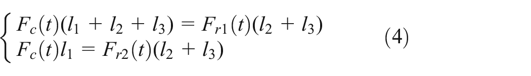

Force analysis of the bearings: (a) the relationship of the shafting-bearing system and (b) the relationship among loads.
The static loads G1 and G2 of Bearing 1 and Bearing 2 are

where the transmission force Fc could be calculated by utilizing equation (1). The distance between the driven part of the coupling and Bearing 1 is l1 = 230 mm, and the distances between bearings and the center of gravity of the generator are l2 = l3 = 460 mm. The mass of the rotor and bearing inner ring assembly part is integrated into the input shaft of the generator, and its gravity G as a static load is determined to be 25,436.76 N.
It is assumed that at the start of the calculation, the rotational load Frk (k = 1, 2) and the static load Gk are in the same direction β(0) = 0°. As the rotational speed decreases, the angle β(t) between the two loads changes over time t. Figure 5(b) shows the combined load on the bearing in both situations where the rotational load is greater than the static load and where the reverse is true. the combined load Flk(t) on the bearing is obtained by summarizing the two situations. Since the axial force of the shafting is mainly absorbed by the coupling, the equivalent dynamic load Pli(t) on the bearing is equal to the combined load Flk(t), after ignoring the axial force, that is

The transmission force Fc on the flat key is solved by the control equation (1), and the correlation between the driveline dynamic model and the combined load on the bearing is established by equations (4)–(6).
Bearing life prediction
The alternating combined load endured by the bearing has a direct impact on its life. The S-N curve of the material used in the NU2326 bearing provides information regarding the relationship between the contact stress and the life of the bearing. When the contact stress is below a certain value, the theoretical life of the material is considered infinite and can be ignored for practical applications. The relationship 23 between the combined load and the contact stress of the NU2326 bearing is

where the GCr15 bearing steel is manufactured using GCr15 bearing steel, with a minimum contact stress (Si min) of 800 MPa. 24 The coefficient K1 is equal to 3.62.
The basic rating life of the bearing L10 is expressed as
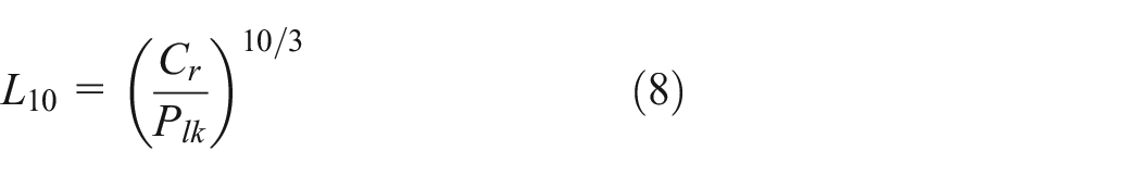
where the basic dynamic load rating is Cr = 920,000 N.
Bearing life at different speeds n is also related to lubrication characteristics. 25 The lubrication characteristics are described by the viscosity ratio, κ. κ is
where the efficacy of lubricants is primarily determined by the separation level of the rolling contact surfaces, which is expressed by the ratio κ of the actual kinematic viscosity v’ to the reference kinematic viscosity v. This study utilizes v′ = 39.6 mm2/s (40°C). 25 And the reference kinematic viscosity v is

The generator bearing is generally clean grease lubrication. When other impurities are mixed in the lubricant, the contamination coefficient ec is obtained. It is related to the pitch diameter Dpw of the bearing. Its contamination coefficient ec is

Based on equations (9) and (10), the change in bearing lubrication parameters during the shutdown is calculated and depicted in Figure 9. The results highlight that the bearing lubrication condition is not favorable at low speeds, as the viscosity is relatively small and the viscosity ratio increases with increasing rotating speed. As the speed increases, the lubrication state becomes more advantageous, and the ideal lubrication state is achieved at the maximum speed. However, it should be noted that exceeding the operating speed may cause the bearing temperature to rise, leading to a reduction in actual kinematic viscosity and viscosity ratio. Equation (10) further demonstrates that the contamination coefficient is positively correlated with the viscosity ratio, hence it exhibits the same trend as the viscosity ratio during shutdown, as shown in Figure 6(b).
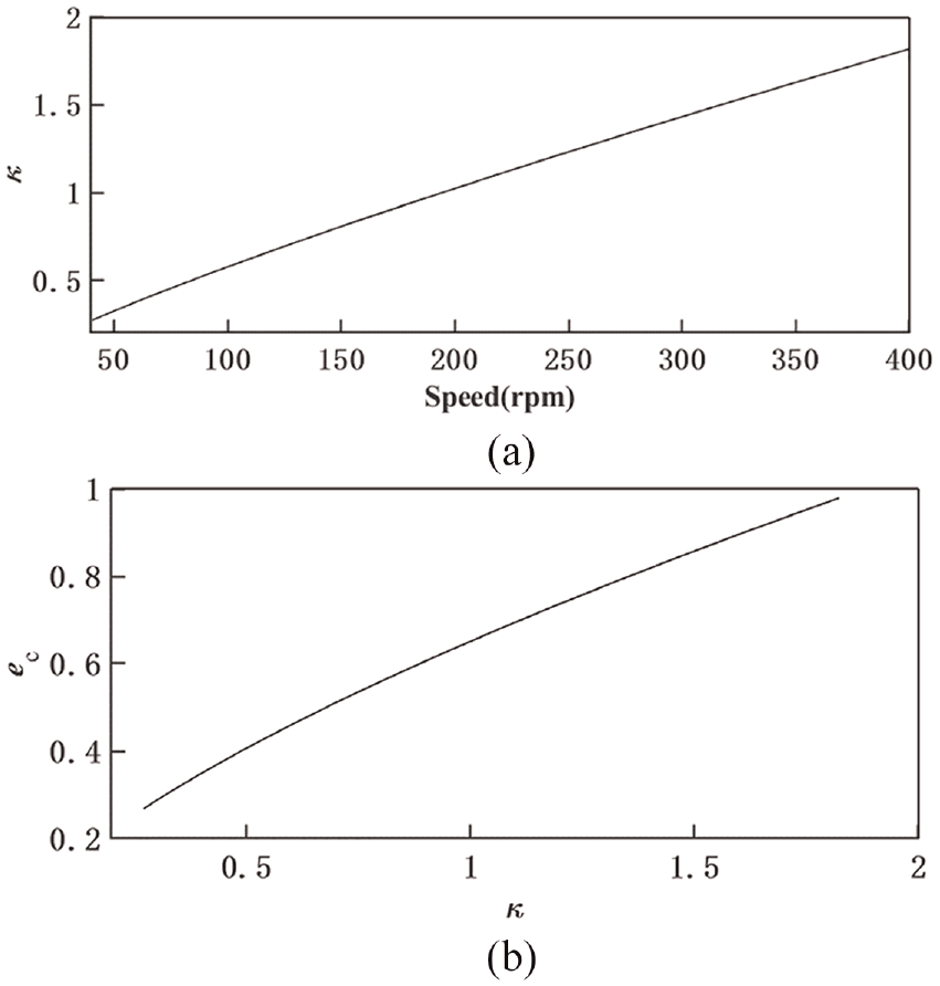
Influence of the lubrication characteristics during shutdown: (a) the change of viscosity ratio κ with rotating speed and (b) variation of contamination coefficient ec with viscosity ratio κ.
The bearing life correction factor aISO incorporates several parameters. The viscosity ratio κ considers the operating temperature of the bearing and its impact on lubricant type, viscosity, rotation speed, and additives. The contamination factor ec takes into account the level of cleanliness in the lubricant and the influence of contaminant particles. The fatigue limit Cu considers various factors such as the bearing type, size, and internal geometry, as well as the contour shape of the rolling element and raceway, the machining quality, and the fatigue limit of the material. The fatigue limit of a roller bearing can be determined by using the bearing dynamics method 26 or the approximate estimation method. 23 Once these parameters are determined, the life correction factor of the bearing can be obtained 27 and be expressed as follows
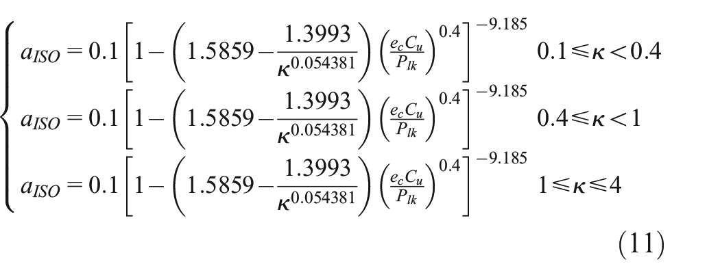
where the basic static load rating of the roller bearing is C0 = 1,230,000 N, and its pitch circle diameter is Dpw = 205 mm. The fatigue limit Cu of the roller bearing is presented as follows

The adjusted rating life of the bearing, incorporating the effects of lubrication characteristics and reliability factors, is described below
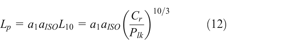
when the reliability is 99%, the reliability life correction coefficient is a1 = 0.25.
The bearing life at each speed could be calculated using equation (12). However, quantifying the effect of the whole shutdown process of the diesel generator set on the bearing’s life is a challenging task. Based on Palmgren-Miner’s linear damage theory, the fatigue damage is linearly related to the number of rotations, and the fatigue damage could be linearly superimposed. When the cumulative damage D reaches a threshold value, fatigue and damage will occur. To evaluate the impact of the shutdown process on the bearing life, cumulative damage (D) is employed as an indicator.
According to the rotational speed n, the actual number of turns of the inner bearing at the time of Δt could be calculated as follows

The present study calculated a total of 120,000 data points during the shutdown of 12 s, which were divided into 120,000 segments. By utilizing equation (12), the number of rotations of the inner bearing and the adjusted rating life of the bearing was determined for each segment. The resulting calculation provided an estimation of the cumulative damage D incurred by the diesel generator set during the shutdown process.

where the required parameters are represented as discrete data, lpj could be calculated utilizing equation (13) and Lpj could be depicted via equation (12), with j representing the segment number in the calculation.
Palmgren-Miner’s linear cumulative damage criterion holds that the damage level of the inner and outer rings subjected to the rolling load increases incrementally as the number of rotations increases.
The combination of loads experienced by Bearing 1 and Bearing 2, Fl1 and Fl2, could be calculated using equation (6). The variation of combined loads of Bearing 1 and Bearing 2 is shown in Figure 7. It can be observed that if the combined load Fli < Fli min, the influence on its life could be neglected. From the figure, it is evident that the shutdown process affects the life of Bearing 1, but not that of Bearing 2. Thus, a detailed analysis of the life of Bearing 1 with the most intense loads is necessary.

Variation of the combined load with time: (a) the combined load of Bearing 1 and (b) the combined load of Bearing 2.
The changes of aISO, L10, and Lp during the shutdown process are shown in Figure 8. As observed, the values of aISO and Lp exhibit a clear decreasing trend during Stage I and Stage II, which is attributed to the fact that the lubrication of the bearings becomes less favorable at lower speeds. When there is manufacturing error in the bearing, the values of the fatigue limit Cu and the bearing life correction factor aISO of the roller bearing will be decreased. These factors can all reduce the bearing life.

The life correction indexes of the bearing during the shutdown.
In Stage I, it is noteworthy that the adjusted rating life Lp decreases dramatically, a result of the decrease in both aISO and L10. The root cause of this decrease is not only due to unfavorable lubrication, but also the triggering of the torsional resonant modal of the diesel generator set’s driveline at 100–140 rpm. This triggers the amplification of the fluctuating torque and transmission force Fc, which, as indicated by equations (4)–(6), increases the combined load on the bearings, leading to a substantial decrease in the values of aISO and L10.
Relationship between the driveline model and the bearing life
According to the above discussion, the bearing life is affected by many factors such as lubrication characteristics, manufacturing errors, geometry, material properties and so on, and the parameters of the coupling play a crucial role in determining the level of speed fluctuation and the combined load on the bearings. This research establishes a correlation between the bearing life and the dynamic response of the driveline system, and provide a theoretical support. This section considers the feasibility and reliability of operation in practice, it can be difficult to alter the mass and moment of inertia parameters of the diesel generator set’s driveline. And the gap and torsional stiffness of the coupling can be adjusted conveniently in the design. And this section will discuss the effect of these parameters on the bearing life.
Influence of the coupling torsional stiffness
The required torque determines the torsional stiffness multiplier, which could vary from 0.5 to 2. The damping parameters of the Geislinger coupling are proportional to the stiffness parameters, meaning that the damping could be derived from the stiffness parameters. The influence of the coupling’s torsional stiffness on the bearing damage is illustrated in Figure 9(a), which displays a substantial variation in the bearing damage value as the coupling stiffness changes. The figure illustrates that reducing the torsional stiffness of the coupling to 0.5 times its original value results in a 90.21% increase in the damage value.
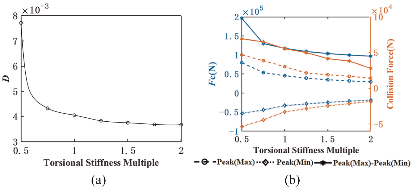
Damage value and force state of the bearing in different coupling torsional stiffness: (a) influence of torsional stiffness of the coupling on damage value D and (b) influence of torsional stiffness of the coupling on the peak values of forces.
The life of the bearing could be reduced and the damage value D could be increased when the bearing is operating under a larger load according to equations (12)–(14). Therefore, it is necessary to analyze the combined load on the bearing. The static load is the constant force of gravity, hence the combined load is directly proportional to the transmission force Fc, as indicated by equations (4)–(6). The transmission force is a critical factor in determining the damage value D. The DFA method was employed to extract the collision force for separate analysis, and the transmission force and the collision force are shown in Figure 9(b). The decrease of the coupling torsional stiffness from the original value significantly contributes to the increase in the absolute value of the transmission force Fc and the collision force, resulting in a significant increase in the bearing damage value D. Conversely, a slight increase in torsional stiffness from the original value decreases these forces.
When the coupling stiffness is reduced to 0.5 times its original value, the system experiences the rebound caused by the excessive softness of the coupling during a collision. During this rebound, the high-order vibration modes of the diesel engine, flywheel, and the driving and driven parts of the coupling are excited, leading to a significant deterioration of the torsional vibration of the system. 8 This causes a significant increase in the damage value of the bearing. Therefore, designers must exercise caution and ensure that the torsional stiffness of the coupling is not too low when determining the parameters of the driveline.
The influence of key gap
The driven part of the Geislinger coupling in the diesel generator set is connected to the generator input shaft via a key, which compensates for axial movement. The key gap is selected according to industry standards, with a maximum tolerance of 0.3 mm and an original gap of 0.28 mm in the driveline. A splined connection with a minimum tolerance of 0.01 mm. If the gap is 0 mm, the driveline is tightly matched. The cases are listed in Table 3.
Calculation cases of different key gaps.

The effect of the key gap on the bearing damage was investigated while keeping the coupling stiffness and damping parameters constant. As shown in Figure 10(a), an increase in the gap leads to a linear increase in the damage value of the bearing. This can be attributed to the transmission force Fc, which determines the combined load. Figure 10(b) show the peak-to-peak value of the transmission force Fc and the collision force, extracted using DFA, under various gaps. The increase of the gap slightly raises the peak-to-peak value of the transmission force (Fc), and the collision force as the component in the transmission force rises remarkably. Conversely, reducing the gap could effectively reduce the collision force, as a decrease in the gap leads to fewer collisions in a fluctuation cycle. In theory, if the driveline were designed to be tightly fitted, there would be no collision force due to the absence of a gap. However, a gap of 0.3 mm would increase the damage value of the bearing by 19.68% at most compared to a tight-fit design. These results suggest that the gap primarily affects the magnitude of the collision force, which in turn raises the damage value of the bearing and decreases its life.

Damage value and force state of the bearing in different gaps: (a) influence of gaps on damage value D and (b) influence of gaps on the peak values of forces.
Design method of the coupling considering the bearing life
The analysis in Section 4 demonstrates that a reduction in the key gap primarily reduces the damage to the bearing by mitigating the collision force. Furthermore, enhancing the torsional stiffness of the coupling can simultaneously decrease the peak transmission force, collision force, and damage value of the bearing, contributing to extended bearing life. However, an increase in the stiffness could lead to a rise in the natural frequency of the driveline of the diesel generator set, potentially compromising stability during idle and other operating conditions.
In this section, a method for designing the stiffness of a coupling while taking into account the life of the bearing is put forward. The design flow is outlined in Figure 11.
Step 1: Determining Available Elastic Coupling Types

Design flow of the coupling stiffness considering the bearing life.
To begin, the types of elastic couplings should be determined, based on the torque transmission requirements of the diesel generator set.
Step 2: Vibration Isolation Theory
Next, the design follows the principles of passive vibration isolation and aims to achieve a preliminary vibration isolation effect by ensuring that the ratio of excitation frequency to the natural frequency of the driveline is greater than
Step 3: Calculating the Combined Load of the Bearing
If the above requirements are met, the elastic coupling parameters would be entered into the driveline dynamic model and the combined load of the bearing would be calculated using equation (6). As the static load is constant due to gravity, equations (4)–(6) show that the combined load is directly dependent on the transmission force Fc. The goal is to ensure that all transmission forces Fc are lower than Fcmin. To achieve this, the design search for different elastic coupling stiffness values until this target is met and determine the final coupling stiffness.
Step 4: High-Stiffness Coupling Plan
If the elastic coupling design fails to meet the requirements in Step 3, the design needs to consider a new high-stiffness coupling plan. The design specifies the frequency range under the main harmonic excitation based on the main working speed range of the diesel generator set and repeats Steps 2 and 3 for the lowest coupling stiffness. The final coupling stiffness parameter should meet the requirement of Fc < Fcmin.
Step 5: Minimizing the Key Gap
Finally, while maintaining the above criteria, the key gap should be minimized as much as possible.
The design of the coupling stiffness for a diesel generator set was carried out according to the method described above. The minimum transmission force Fcmin of the bearing, as determined by equations (4)–(6), was calculated to be 48,838.56 N, with a corresponding permissible peak value of 36,120.18 N. However, the simplified 3-DOF model indicated that the elastic coupling scheme could not guarantee that the peak value of Fc would be less than 36,120.18 N, leading to the introduction of a high-stiffness coupling. The maximum speed of the diesel generator set was 1000 rpm, resulting in an 8.0 harmonic frequency of 133.33 Hz, and the natural frequency of the driveline was required to be greater than 188.56 Hz.
The design of the coupling took into account the actual production requirements, considering the maximum torque transmission, rotational speed, dimensions, as well as the stiffness and damping parameters determined based on the above design method. A tight-fit high-stiffness coupling was designed and produced in accordance with the quality assurance requirements of ISO 4863:1984, as depicted in Figure 12. This design eliminated the key and gap, and the axial movement was supplemented by a diaphragm spring. This coupling was employed to connect the input shaft of the generator,

Schematic diagram of the large stiffness coupling.
From the calculation of numerical results as shown in Figure 13(a), it indicates that the driveline equipped with this coupling could effectively avoid torsional vibration resonance and collisions during the shutdown process. The maximum peak value was determined to be 33,926.07 N, which was smaller than Fcmin. The damage value D of the diesel generator set was calculated to be 0.0023, a decrease of 43.19%, thereby significantly improving the bearing life.

Effect of the coupling with high stiffness: (a) transmission force Fc calculated under high rigidity coupling and (b) torsional vibration test results.
From the torsional vibration test results as shown in Figure 13(b), the speed fluctuation at the flywheel was a stable and non-resonant during the shutdown process, making it favorable for long-term bearing operation.
Conclusion
(1) During the shutdown process of the diesel generator set with an elastic coupling, it has been observed that transmission forces and collision forces generated by the key could be amplified, when the excitation frequency approached the driveline natural frequency. The amplified forces could significantly increase the combined load on the bearing and reduce the bearing life.
(2) By developing the torsional vibration dynamic model of the driveline, a correlation between the bearing life and the combined load of the driveline is established, and the proposed cumulative damage value enables a quantitative assessment of the influence of the transmission force and the resonant-triggered collision force on the bearing life during the shutdown process of the diesel generator set.
(3) The effect of the torsional stiffness and the key gap of the coupling on the bearing life is investigated. Results reveal that a lower torsional stiffness of the coupling leads to higher peak values of both the transmission force and the collision force, which would notably deteriorate the life of the bearing. Additionally, the increase in the gap of the coupling results in a rise in the collision force within the transmission force, causing a higher level of damage to the bearing and reduced service life of the bearing.
(4) A coupling stiffness design should consider the bearing life. The proposed flow path and the scheme could effectively improve the vibration performance during the shutdown process of the diesel generator set. The validity of the proposed large stiffness coupling scheme is verified by an experiment and results indicate a significant reduction in damage value, thereby improving the lifespan of the bearings.
Footnotes
Handling Editor: Chenhui Liang
Declaration of conflicting interests
The author(s) declared no potential conflicts of interest with respect to the research, authorship, and/or publication of this article.
Funding
The author(s) disclosed receipt of the following financial support for the research, authorship, and/or publication of this article: This work was supported financially by the National Natural Science Foundation of China [No. 51875482] and the Natural Science Foundation of Sichuan Province of China [No. 2022NSFSC0416].