
Abstract
The nonlinear dynamics of the composite shaft rotor-bearing system are greatly affected by the orientation angle layer and its proportion of the ply, i.e., the ratio of the orientation angle layer in the laminate. This paper presents a nonlinear dynamic analysis of a composite rotor-bearing system with pedestal looseness that considers the nonlinear oil film force and the pedestal looseness. Nonlinear phenomena including periodic, quasi-periodic, and chaotic motions are analyzed. The analysis results indicate that the stiffness and damping coefficients of a composite shaft tube can be influenced strongly by the laminate parameters, which can in turn affect the instability speed of the rotor system. To enhance the oil film instability speed of the composite rotor system, it is essential to maximize the ratio of the small orientation angle layer or the ±45° layer. Additionally, increasing the ratio of the small orientation angle layers in the shaft tube leads to a higher rotational speed for loosening instability. The research results obtained in this paper have important theoretical value for the design of composite rotor-bearing systems.
Keywords
Introduction
Carbon fiber-reinforced plastics (CFRPs) offer several advantages, including high strength-to-density ratios, high stiffness-to-density ratios, and good fatigue resistance. These properties make CFRPs ideal materials to improve the dynamic characteristics of high-speed rotating machinery. 1 At present, CFRPs are being used increasingly frequently in transmission components in various fields, including automobiles, shipping, and aviation. Accurate analysis of the dynamic performance of composite rotors is essential to ensure the stable operation of these rotors. 2 Instability of the oil films and pedestal loosening are commonly observed in rotor-bearing systems. 3 Many researchers have studied the nonlinear dynamic characteristics of isotropic rotor systems, and the mechanism of instability related to pedestal looseness has been documented well.4,5 However, there is a lack of existing research on the nonlinear dynamic characteristics of anisotropic composite rotor-bearing systems.
In recent years, increasing focus has been placed on the research into composite rotors, with researchers proposing a variety of models to analyze both the linear and nonlinear dynamic characteristics of these rotors. In terms of their linear dynamics, the critical speed and instability thresholds of composite rotors have mainly been studied through use of the equivalent modulus beam theory, the improved equivalent modulus beam theory, the simplified homogeneous beam theory, and layer-wise beam theory. 6 In terms of the nonlinear dynamics, Gubran et al. 7 and Ri et al. 8 studied the coupled vibrations of asymmetrically laminated CFRP drive shafts on the bases of the improved equivalent modulus beam theory and the simplified homogenized beam theory, respectively. Shaban et al. 9 conducted studies of the nonlinear dynamic characteristics of CFRP rotors with geometric nonlinearity based on the improved equivalent modulus beam theory and the Hamiltonian principle. The bending-stretching and bending-torsion dynamic coupled equations of the rotor were derived. The multi-scale method was then applied to solve the discrete equations, and an analytical expression to describe the forced vibration of the CFRP rotor near the main resonance was obtained; the impact of the eccentricity on the amplitude bifurcation point was also analyzed. He et al. 10 established a nonlinear finite element analysis model of composite beams based on the improved equivalent modulus beam theory and using the principle of minimum potential energy. Through parameter analysis, the impact of the span-depth ratio of the composite beams on the shear effect was discussed. Wang et al. 11 and Uddin et al. 12 studied the large-scale vibration behavior of a CFRP geometrically nonlinear cylindrical shell, and determined the effect of the excitation frequency on the system’s nonlinear dynamic response. Arab et al.13,14 studied the critical speed and the unbalanced response of an asymmetric layered CFRP rotor on the basis of the discrete layer beam theory and compared the results with those based on the equivalent modulus beam theory, along with experimental results. Their results indicated that the discrete layer beam theory can reflect the stress–strain characteristics of the layers accurately by considering the effects of the layering order and the coupling effects fully. Zhang et al. 15 applied the incremental harmonic balance (IHB) method to an analysis of the nonlinear vibration of a composite shaft-disk rotating system that took the nonlinear deformation into account and also studied the impact of layer parameter changes on the frequency response characteristics. Nezhad et al. 16 used the harmonic balance method to analyze the nonlinear vibration characteristics of composite shafts. Liu et al.17,18,19 focused on the nonlinear forced vibrations of a functionally graded composite cylindrical shell and evaluated the effects of the main factors on the nonlinear vibration responses and bifurcation of rotating shells. Additionally, other researchers have studied the internal resonance phenomenon in composite rotors at supercritical speeds and determined the effects of the material’s internal resistance on the nonlinear vibration of the composite rotor.20,21,22 Wang et al. 23 investigated chaos, jumping, and other complex nonlinear phenomena in the magnetorheological damper-rotor system, and found that the nonlinearity level can be alleviated effectively by applying an appropriate excitation current and oil supply pressure. Zhao et al.24,25 developed dynamic modeling methods to investigate the coupling vibrations of flexible shaft systems, and then studied the natural frequencies and dynamic responses of the rotor system. Current research on composite rotors is primarily focused on the linear dynamics, with specific focus on the natural frequencies and instability thresholds caused by internal damping. However, there is a lack of research into the nonlinear dynamics of composite rotors caused by the bearing and loosening, and no research has been conducted to date on the effects of the composite laminate parameters on the nonlinear dynamic characteristics. Further research in these areas could provide valuable insights into the behavior of composite rotors and inform the design and use of these rotors.
This paper focuses on the nonlinear dynamic characteristics of a rotor system caused by the bearing. Specifically, the effects of oil film oscillation and bearing looseness on the system’s nonlinear dynamics are examined. The study investigates the nonlinear dynamic characteristics of a composite rotor-bearing system. In this study, the dynamic equations of a seven-degrees-of-freedom (7-DOF) model of a composite rotor-bearing system was established using the layer-wise theory of composite materials, the Capone bearing oil film force model, and the loose bearing piecewise nonlinear stiffness/damping model. The Runge–Kutta iteration method was used to calculate the numerical solution for the dynamic response of the system, and the nonlinear dynamic characteristics of the composite rotor-bearing system and the influence of the laminate parameters on this system were studied.
The Composite Rotor-Bearing System
Dynamic model of rotor pedestal looseness
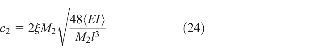
Figure 1 shows the structure of a typical composite rotor-bearing system consisting of composite shaft tubes, sliding bearings, and concentrated mass discs. The sliding bearings, which are located at both ends of the composite rotor, are the same. The geometric centers of these bearings at the right and left ends are designated O1 and O3, respectively, and the oil film thickness is h. The left-end bearing has a loose clearance of δ. O2 is the geometric center of the disk, O2’ is the center of mass of the disk, the eccentricity is b, and the damping coefficient is c2.

Mechanical model of the composite rotor-bearing system.
Let (x1,y1) be the displacement of the axle neck at the non-loose end, let (x2,y2) be the displacement of the geometric center of the disk, let (x3,y3) be the displacement of the axle neck at the loose end, let y4 be the displacement of the support in the y direction, and let ω be the rotational speed. The dynamic equations for the 7-DOF model of the composite rotor-bearing system can be expressed26,27,28 as shown below.

Here, c1, c2, and c3 are the damping coefficients of bearing O1, the composite shaft, and bearing O3, respectively. M1, M2, M3, and M4 are the equivalent lumped masses of bearing O1, the disk, bearing O3, and the loose pedestal, respectively. The equivalent lumped masses can be calculated using the following formula:

In the formula above, m1, m2, m3, m4, and mr are the actual masses of bearing O1, the disk, bearing O3, the loose pedestal, and the composite shaft tube, respectively.
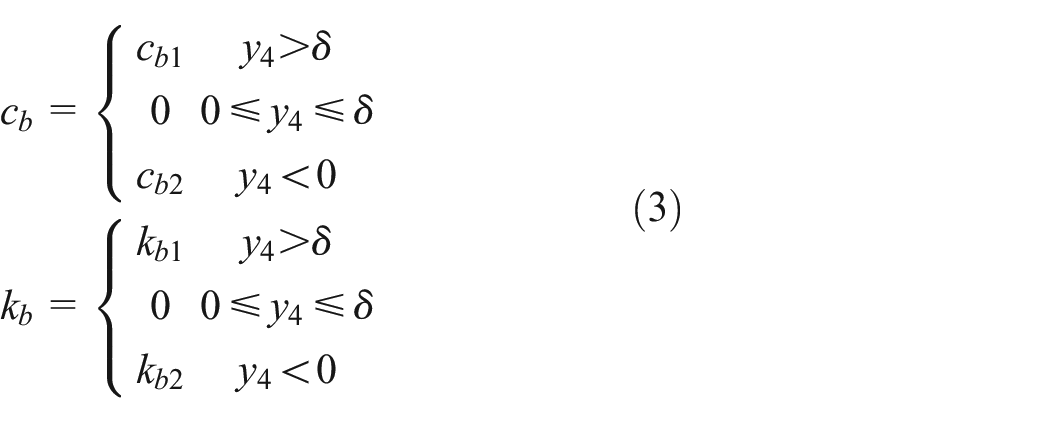
Fx and Fy are the nonlinear oil film force components acting in the x and y directions, respectively. k is the stiffness of the composite shaft tube. cb and kb are the damping and stiffness coefficients of the loose pedestal relative to the ground, respectively. The piecewise nonlinear stiffness damping model of the loose bearing is given as follows: 3
To enable further analysis, a dimensionless equation of the following form was used:
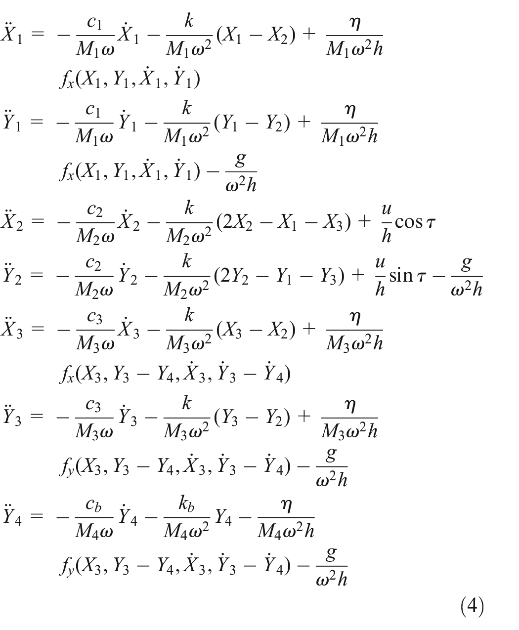
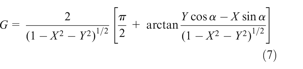
In the equation above, the dimensionless transformations are τ=ωt, Xi=xi/h, and Yi=yi/h. η is the Sommerfeld coefficient of the oil film force. 4 In addition, fx and fy are the dimensionless nonlinear oil film forces. The relationship between these nonlinear oil film forces fx and fy is: 4

where


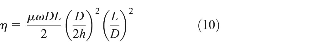
where μ is the viscosity coefficient of the oil film, D is the plain bearing diameter, and L is the bearing length.
Equivalent coefficient of the composite shaft
In equation (3), k and c1 represent the equivalent flexural stiffness and the equivalent damping coefficient of the composite shaft, respectively, which will both be calculated using layer-wise theory in this paper. The thickness dimension of one fiber-reinforced composite layer is much smaller than the total wall thickness of the composite shaft tube. Each layer in the composite shaft tube is considered to be in a state of plane stress, as shown in Figure 2.

Coordinate system of laminated composite.
Equivalent flexural stiffness of the composite shaft
CFRP is an orthotropic material. In the case of linear elasticity, the constitutive relationship of a single layer in the material local coordinate system (1, 2, 3) is shown as follows:

where

To enable the mechanical analysis of the composite rotor, it is necessary to perform an off-axis transformation according to the constitutive relationship and the fiber orientation angle of the layer. The constitutive relationship in the global coordinate system is: 29

Here,

The axial modulus of the single composite layer can be calculated using the following formula:

By combining this modulus with the layer-wise theory, 20 the equivalent flexural stiffness of the composite shaft tube can be obtained as follows:
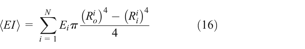
Because the composite shaft tube is a typical thin-walled structure, the influence of the shear strain is small and can be ignored when bending deformation occurs. The Euler–Bernoulli beam theory is therefore used to calculate the equivalent flexural stiffness coefficient k of the composite shaft:

In equation (17), l is the length of the composite shaft.
Equivalent damping coefficient of the composite shaft
Previous research on the damping loss factor of composite shafts 30 showed that composite shafts also have orthotropic properties in terms of bending damping. The specific damping capacity (SDC) matrix can be used to describe each composite layer. The SDC matrix consists of elements that represent the energy dissipation properties of the composite layer in three main directions, and is shown as follows:

In equation (18), Ψ11 is the damping loss factor in the fiber direction, Ψ22 is the damping loss factor in the vertical direction of the fiber, and Ψ12 is the damping loss factor in the shearing direction. When the fiber orientation angle of the ith layer is θi, the SDC matrix of the ith layer is given by:

where

According to the concept of energy dissipation, the damping loss factor can be expressed as the ratio of the strain energy dissipation to the total strain energy in each vibration period. The equations for these expressions are given as follows:

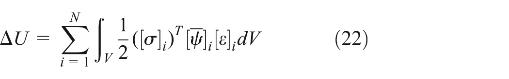

where ΔU is the strain energy dissipation, U is the total strain energy, N is the total number of composite layers, and V is the volume of the composite shaft tube. In addition, [σ] i =[σxσyτxy] T and [ε] i =[εxεyγxy] T . Therefore, the equivalent damping coefficient of the composite shaft can be calculated using the following equation, based on Euler–Bernoulli beam theory:
Analysis of Nonlinear Dynamic Characteristics
The geometric parameters of the composite rotor-bearing system studied in this paper are listed in Table 1, and the properties of the CFRP material are given in Table 2. Although the unbalanced mass of the rotor has a major impact on the dynamic characteristics of the system, it is not the research focus of this paper. Therefore, the unbalanced magnitude under all working conditions remains the same.
Geometrical parameters of the composite rotor-bearing system. 31
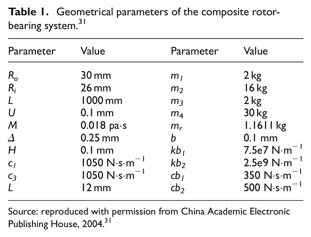
Source: reproduced with permission from China Academic Electronic Publishing House, 2004. 31
Material parameters of the composite rotor. 30

Source: reproduced with permission from World Scientific, 2004. 30
In Table 1 above, the parameters represent the following:
Ro, Ri: outer and inner radii of the composite shaft, respectively. l: length of the composite shaft.
u: bearing clearance. μ: viscosity coefficient of the oil film. δ: maximum loosening clearance. h: oil film thickness. L: bearing length. c1, c3: damping coefficients of bearings O1 and O3, respectively. m1, m3: masses of bearings O1 and O3, respectively.
m2: mass of the disk. m4: mass of pedestal looseness. b: unbalanced magnitude of the disk. kb1, kb2: loose pedestal stiffnesses relative to the ground. cb1, cb2: loose pedestal damping coefficients relative to the ground.
The stiffness and damping of the composite shaft tube will vary with the laminate parameters because of the anisotropy of the CFRP material. To perform a comprehensive analysis of the dynamic characteristics of a composite rotor-bearing system with a pedestal looseness fault, it is essential to investigate the diverse range of dynamic behavior of the rotor system with various laminate parameters. Typically, the composite shaft tube is fabricated using filament winding technology, where the minimum fiber winding angle is ±15°. The smaller orientation angle is beneficial in improving the bending stiffness of the composite shaft, while the ±45° layers maximize the damping ratio.30,32. Therefore, in this paper, ±15°, which has the greatest effect on stiffness enhancement, and ±45°, which makes the greatest contribution to damping, are selected as the typical fiber orientation angles for design of the laminate schemes. The laminate schemes when using the same number of layers but different orientation angles are presented in Table 3. According to the method given in Section 2.2, the stiffness and damping parameters of the composite shafts were calculated.
Laminate schemes and parameters.

The Runge–Kutta numerical integration method was used in this work to solve the differential equations. The integration step was selected to be τ/512. Here, τ is the dimensionless period of the system motion, and the solution error was set to 1×10⁻⁶. The steady-state numerical solutions for the system were obtained via an iterative approach, and the transient solutions were discarded. Collection of the steady-state solutions at different rotational speeds and for different laminate schemes allows the nonlinear dynamic characteristics to be analyzed and discussed. The flowchart and the solution process are illustrated in Figure 3.

Flowchart and solution process for the nonlinear dynamic characteristics analysis.
Time-domain characteristics of composite rotor-bearing system
The bifurcation diagram of Y3 at the loose end of the composite rotor-bearing system was obtained by calculating the motion equation for the B1 laminate scheme within the rotational speed range from 200 to 2000 rad/s. Figure 4 shows that the system exhibits various motion states, including periodic, approximately periodic, and chaotic, as the rotational speed increases. In the speed range from 200 to 600 rad/s, the composite rotor’s response was a single-cycle stable periodic motion. When the rotational speed was 600 to 670 rad/s, a period-2 frequency division motion occurred. In the speed range from 670 to 700 rad/s, the system passed into chaotic motion. At the rotational speed of 700 rad/s, the system left the chaotic motion region and entered a single-cycle motion region again. As the rotational speed continued to increase, the system entered chaotic motion again at 810 rad/s.
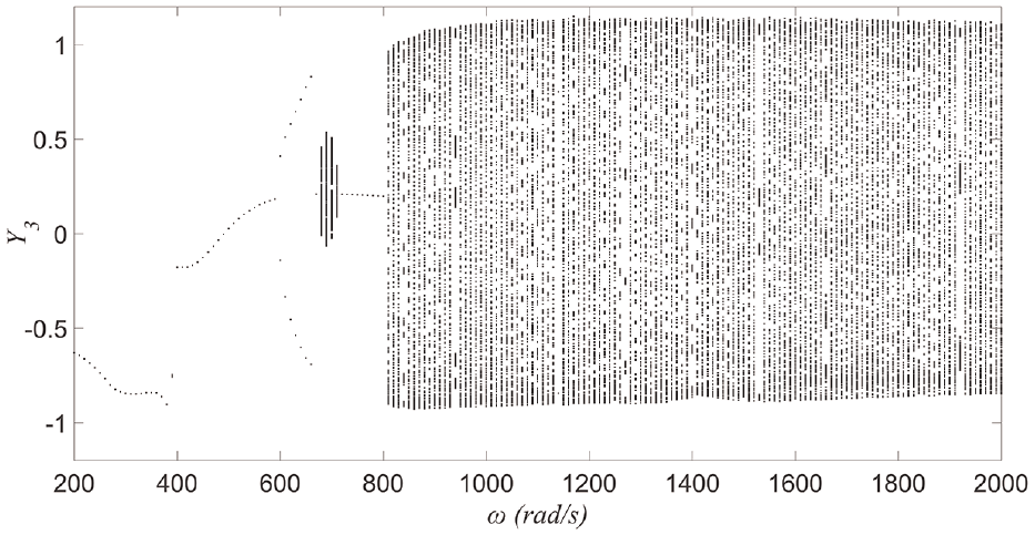
Bifurcation diagram of composite rotor-bearing system in the Y3 direction of scheme B1.
To show the typical dynamic response characteristics of the system and enable discussion of the causes of chaotic motion, the response diagrams for the two ends of the composite rotor-bearing system when ω=620 rad/s and 1000 rad/s were analyzed, as shown in Figures 5 to 8.

Response of the end of the composite rotor system without looseness when ω=620 rad/s: (a) Amplitude curve in the Y1 direction, (b) Motion trajectories of O1, (c) Phase diagram in the Y1 direction and (d) Poincaré map in the Y1 direction.

Response of the end of the composite rotor system with looseness when ω=620 rad/s: (a) Amplitude curve in the Y3 direction, (b) Motion trajectories of O3, (c) Phase diagram in the Y3 direction and (d) Poincaré map in the Y3 direction.
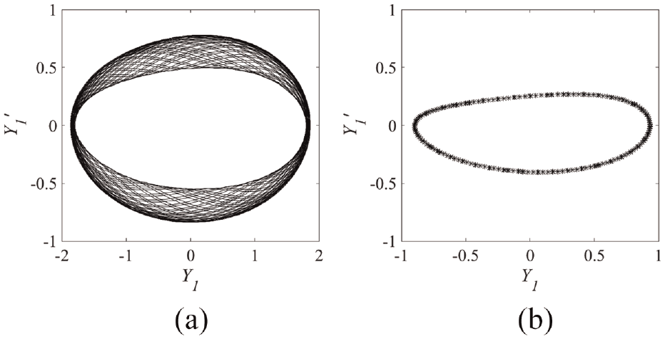
Response of the end of the composite rotor system without looseness when ω=1000 rad/s: (a) Phase diagram in the Y1 direction and (b) Poincaré map in the Y1 direction.

Response of the end of the composite rotor system with looseness when ω=1000 rad/s: (a) Phase diagram in the Y3 direction and (b) Poincaré map in the Y3 direction.
When ω=620 rad/s, the Poincaré maps of both the non-loosening end O1 and the loose end O3 consisted of two points, as demonstrated in Fig. 5(d) and Fig. 6(d), respectively. This suggests that the system is undergoing period-2 movement. This period-2 motion is caused by the oil film whirl. Comparison of the motion trajectories, the amplitudes, and the phase diagrams in the Y1 and Y3 directions shows that the loose and non-loosening ends move synchronously. This occurs because at this speed, the centrifugal force caused by the mass imbalance is less than the gravity of the mass of the pedestal looseness during rotation, and thus the stiffness and damping of the loose pedestal damping relative to the ground remain unchanged. In addition, the system is not influenced by the pedestal looseness fault. At this rotational speed, the nonlinear oil film force of the bearing is the main factor causing the bifurcation instability of the system.
When ω=1000 rad/s, the Poincaré map of the non-loosening end (as shown in Fig. 7(b)) is a closed curve, which indicates that the non-loosening end is in a state of quasi-periodic motion. With increasing rotational speed, the oil film oscillates and then becomes unstable. The Poincaré section of the loose end (as shown in Fig. 8(b)) is a cluster of dense points, which indicates that the loose end is in a state of chaotic motion. As the rotational speed increases, the centrifugal force that results from the imbalance becomes greater than the gravitational force of the mass of the loose pedestal during the rotation. This causes the stiffness and damping characteristics of the loose pedestal to become piece-wise nonlinear, while also causing the oil film to be unstable and to be oscillating. Nonlinear factors contribute to the sensitivity of the vibration trajectory to the initial position, which results in noncoincidence of the motion trajectories in each cycle. As a result, the loose end experiences chaotic motion states caused by the oscillation of the oil film and the pedestal looseness.
Frequency-domain characteristics of the composite rotor-bearing system
To analyze the frequency domain characteristics of the composite rotor system at various rotational speeds, a Fourier transformation was performed on the time-domain curve of the vertical vibration displacement Y3 of the rotor’s loose end O3. The range of this analysis was from 200 rad/s≤ω≤2000 rad/s, and the resulting spectrum cascade of the amplitude-frequency curve is shown in Figure 9. The rotational frequency is defined as fr and the first-order natural frequency of the composite rotor system is fn. When 200 rad/s≤ω<600 rad/s, the composite rotor response is a synchronous positive precession. In addition, the frequency fr and its harmonics, e.g., 2fr and 3fr, appear, excited by the imbalance of the rotor system. When the speed reaches 600 rad/s, the oil film whirl begins to become violent, where the whirl frequency of the oil film is approximately half of the rotational frequency fr. Therefore, the frequency fr/2 component begins to appear in the amplitude-frequency curve. Simultaneously, the frequency of the first-order oil film whirl is approximately 47.75 Hz. When the rotational speed exceeds 810 rad/s, the vibration response of the composite rotor system becomes more complex, with fn, 2fn, 3fn and other multiples, including fr−4fn, fr−3fn, and fr−2fn, also appear. This occurs because this speed range is close to the oil film oscillation speed; the vibration becomes more severe, which is then more likely to cause the bearing support to loosen. The results of the frequency-domain analysis indicate that multiple frequencies are more pronounced at the higher rotational speeds when compared with the lower speeds, thus indicating the strengthening of the nonlinearity and instability in the case of pedestal looseness.

Spectrum cascade of the end with looseness about Y3.
For a composite shaft tube with a fixed laminate scheme, we use a homogenization method to obtain the equivalent stiffness and damping coefficients, thus enabling the dynamic equations for the anisotropic rotor-bearing system to be solved using the same method that was used for isotropic rotors. Without changing the laminate parameters, the time-domain and frequency-domain characteristics of the composite rotor are consistent with those of the typical Jeffcott rotor.4,5,26 The results verify the correctness of the nonlinear dynamic model and the numerical solution method presented in this paper.
The Effect of the Laminate Parameters on Rotor Stability
To investigate the effect of the laminate parameters on the composite rotor’s stability, the nonlinear dynamic equations for the composite rotors with the different laminate schemes were solved and the results are listed in Table 4. The bifurcation diagrams for the loose end Y3 of schemes B2 to B4 are presented in Figures 10 to 12.
Motion state of the composite rotor-bearing system.

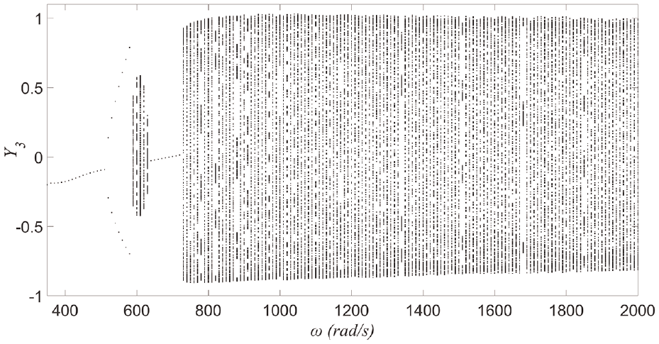
Bifurcation diagram of the rotor system in the Y3 direction of scheme B2.

Bifurcation diagram of the rotor system in the Y3 direction of scheme B3.

Bifurcation diagram of the rotor system in the Y3 direction of scheme B4.
When the rotational speed of the composite rotor-bearing system increases, the system will then experience different motion states, and the details of these states are presented in Table 4. The oil film instability speed and the loosening instability speed were extracted to perform a comparative analysis, with results as shown in Figure 13.

Influence of the laminate parameters on the instability speed.
From the analysis of the oil film instability, it was observed that the unstable oil film whirl speed was higher for composite shaft tubes with higher stiffness or damping ratios. In contrast, for composite shaft tubes with intermediate stiffness and damping ratios, the unstable rotational speed was lower. The oil film instability is caused by vibrations induced by the bearing oil film force, and the oil film force is closely related to the bearing neck displacement. For a composite shaft tube with higher bending stiffness, the displacement amplitude of the bearing neck caused by the same unbalanced force of the rotor is smaller. In the case of a composite shaft tube with greater internal damping, the vibrations caused by the unbalanced force decrease more rapidly, and this results in a smaller bearing neck displacement. This reduced displacement leads to a reduction in the tangential instability force of the oil film. When the tangential instability force is smaller than the bearing damping force, then oil film instability is less likely to occur as a result.
The bearing loosening instability speed comparison indicated that the loosening instability of the composite rotor-bearing system was mainly influenced by the stiffness of the composite shaft tube. When the bending stiffness of the composite shaft tube increases, the unstable rotational speed caused by the looseness also increases. This occurs because a rotor with higher stiffness is subjected to smaller bending deflections under the same imbalance and rotational speed conditions, which will result in lower imbalance forces acting on the bearing neck. When the unbalanced force is lower than the gravity force of the pedestal looseness mass, loosening instability will not then occur. However, under the current unbalanced conditions, the loosening instability occurs within the supercritical speed range, and internal damping of the composite shaft is unable to reduce the shaft vibrations. This is the reason why the composite shaft’s internal damping has little effect on the loosening instability speed.
A smaller orientation angle is beneficial in improving the bending stiffness of the composite shaft, but the ±45° layers maximize the damping ratio. When designing the dynamic performance of the composite rotor-bearing system, it is recommended that the ratios of the small orientation angles or the ±45° layers are maximized to improve the oil film instability speed of the system. Additionally, increasing the ratio of the small orientation angle layers can help to prevent bearing loosening instability.
Conclusion
This study has focused on analysis of the nonlinear vibration characteristics of the composite rotor-bearing system and how its stability is affected by the laminate parameters. The main conclusions drawn are presented as follows:
(1) Based on the parameters used in this study, the composite rotor-bearing system will experience periodic, almost periodic, and chaotic motion states as the rotational speed increases. It was observed that oil film instability occurs before the loosening instability.
(2) In the full speed domain, the rotational frequency fr may have frequency doubling components because of the unbalanced mass. When oil film instability occurs, half-frequency components of fr can be observed. Following the loosening instability, the frequency components of the system become more complex, and the components in this case include a combination of the rotational frequency fr and the natural frequency fn.
(3) To improve the oil film instability speed of the composite rotor system, it is important to maximize the ratios of the small orientation angle layers or the ±45° layers during design of the dynamic performance of the rotor. The rotational speed of the loosening instability is primarily dependent on the composite shaft tube’s stiffness, and increasing the ratio for the small orientation angle layers in the shaft tube leads to a higher rotational speed of loosening instability.
Footnotes
Handling Editor: Chenhui Liang
Declaration of conflicting interests
The author(s) declared no potential conflicts of interest with respect to the research, authorship, and/or publication of this article.
Funding
The author(s) disclosed receipt of the following financial support for the research, authorship, and/or publication of this article: This work was supported by the National Natural Science Foundation of China (No. 52105095), the Science and Technology Research Project of Hubei Provincial Department of Education (No. B2021205), and the Xiangyang Science and Technology Project (No. 2022ABH006135).
Data Availability Statement
Some or all data, models, or code that support the findings of this study are available from the corresponding author upon reasonable request.