
Abstract
Railway Balise is widely used in the Balise-based train control system to provide accurate location information for the safe operation of trains. In order to evaluate and analyze the functionality and interface test of a new designed Balise more rigorously and accurately, this paper build a magnetic field-circuit coupling model to quantify the internal physical function and external interface performance of the Balise. Based on the electromagnetic field theory, the down-link and up-link magnetic field models were set up which describes the relationship between the Balise and the test antenna. Then based on the equivalent circuit model, the energy conversion circuit model and the data transmission circuit model were derived, and the complete coupling model is established for functionality and interface simulation tests. Moreover, the physical behavior and interface characteristic of Balise in different situations are validated and analyzed, followed by the analysis of magnetic field conformity, I/O characteristics, impedance, start-up behavior, and up-link signal characteristics. The results show the start-up time of the Balise functionality test decreases with increasing down-link magnetic field. Furthermore, Balise impedance can be used as a new dynamic detection parameter of the Balise. Finally, the down-link magnetic field will slightly affect the uplink signal characteristics.
Keywords
Introduction
In recent years, Balise is used to provide accurate location information for the safe operation of trains, and plays an indispensable role in the Balise-based train control system. 1 As the information source of train movement authorization, the key issue and challenge facing Balise is that the performance of the Balise is usually dynamic changes, which is caused by the joint influence of multiple nonstationary factors. 2 The performance prediction, analysis, and test of Balise has always been an important topic for Balise Transmission System (BTS) used in the Balise-based train control system.3,4
The performance of the Balise is mainly analyzed in two forms: laboratory test and high-speed comprehensive inspection train dynamic test.5,6 Among these forms, the laboratory test directly determines the dynamic performance of the final working Balise, which is particularly important for the position information transmission of the Balise. According to the test specification of BTS (TB/T 3544-2018), the laboratory test of a Balise is divided into functionality test and interface test. Functionality test usually refers to the internal performance of the Balise, while interface test refers to the external performance of the Balise. The working performance of a Balise depends on the Balise, but it cannot be obtained simply by analyzing the physical circuit of the Balise. It is also necessary to analyze the complex coupling relationship between the train and the Balise. This relationship must be analyzed through a scientific, reasonable, and accurate method, which requires not only information about the physical circuit of the Balise but also the interface of the BTS. Moreover, the test time of laboratory physical experiment method is usually unacceptable in the optimal design of a Balise. Thus, a high precision simulation test model for a Balise that considers the coupling relationship between magnetic field and circuit must be proposed.
Some methods and models for analyzing the performance of the Balise have been proposed, such as electromagnetic simulation method, discrete event simulation framework-based model, inductive coupling model, equivalent circuit model, and equivalent current model. The electromagnetic simulation method describes the data transmission process of the Balise through finite element method (FEM), with the aim of clearly understanding the magnetic field distribution of the Balise and the effect of the electromagnetic pulse on the magnetic field.7,8 In addition, the antenna parameter of the FEM-based model can be used to study the electromagnetic susceptibility (EMS) of the Balise information transmission process. 9 The discrete event simulation framework-based model is established by mapping the inductive communication system of the Balise into the far-field communication modeling. This model aims to quantify the effect of communication quality degradation on the efficiency of railway operation and obtain performance indicators of the physical layer.10,11 An inductive coupling model is used to analyze the dynamic transmission performance based on the electromagnetic field theory, and some mathematic equations are derived to describe the performance of the Balise over its entire transmission link.12,13 The equivalent circuit models are proposed to analyze the mutual inductance and complex environmental adaptability that first utilize the equivalent circuit for inductive process and is promising for various environmental conditions.14,15 The equivalent current model requires a large number of black box laboratory test data to study the input-output characteristic of a Balise. 16
In summary, few studies on the performance of the Balise accurately quantified the field-circuit coupling relationship, barely considering the influence of various dynamic conditions on the functionality and interface performance. The completeness of the model’s key physical elements and their coupling effects is still in high demand. Due to the diversity and complexity of structure, lacking thorough consideration of above-mentioned interrelationship and performance analysis during the design and test process of a new Balise, would impede the improvement of the development efficiency of the Balise. Authors proposed an equivalent impedance model to analyze the down-link transmission quality of the BTS, where the field-circuit coupling model was used to describe the interface performance of the Balise. 17 However, this model still fails to comprehensively and accurately describe the dynamic characteristics and physical behavior of the Balise, such as the fluctuation of functionality or interface performance caused by nonstationary factors.
Consequently, to evaluate and analyze the functionality and interface test of a new designed Balise more rigorously and accurately, this paper focuses on the magnetic field-circuit coupling model. A new simulation test model for Balise is proposed by coupling a down-link magnetic field model, up-link magnetic field model, energy conversion circuit model, and data transmission circuit model.
The rest of this paper is organized as follows. Section “Operating principle of Balise” formally describes the operating principle and laboratory test items of the Balise. Section “Model development” illustrates the proposed model. Section “Experiments and analysis” presents the experiments and result analyses, and the concluding remarks are given in Section “Conclusions.”
Operating principle of Balise
The Balise operating is accomplished by the down-link energy and up-link data transmissions shown in Figure 1. When a train passes, the Balise is activated by the train and transmits the location information to the Balise Transmission Module (BTM) on the train. Then, the telegram is extracted and input to a vital computer. Meanwhile, the vital computer calculates the speed profile from the telegram information to realize real-time train speed control. During ground-to-train transmission, the Balise physical system converts the received energy to make it switch from a dormant state to a working state. The telegrams stored in the Balise are modulated as the up-link signal and transmit to the BTM antenna.

Operating principle of Balise.
The Balise physical system does not contain any power source. Instead, the energy employed to power the Balise is the energy of the electromagnetic signal sent by the BTM. Meanwhile, the Balise heavily depend on the up-link transmission process to output respond. Therefore, it is necessary to use all the above transmission links as part of the operation process of the Balise and learn their characteristics for Balise testing and analysis. This can improve the test and analysis accuracy of the model compared to the univariate Balise physical system.
Model development
In this section, a framework for the magnetic field-circuit model of the Balise is built. Then the magnetic field model applied for the energy and information transmission of the Balise is explained. Finally, the equivalent circuit model of the Balise physical system is developed in detail.
Modeling framework
As mentioned in section “Operating principle of Balise,” the analysis ability of a Balise model is normally poor under nonstationary factors. Therefore, accurately quantification of the coupling relationship between the BTM antenna and the Balise should be able to systematically handle the random nature in the energy and information transmission process of the Balise. In this research, therefore, we propose a magnetic field-circuit model framework for accurately quantification of the Balise with energy and information transmission processes. The key new idea in this framework is a field-circuit coupling method, which is the first attempt to quantify the internal physical function and external interface performance of the Balise.
The proposed framework is composed of four sequentially executed models, as shown in Figure 2. The first step is to establish the magnetic field model of down-link energy transmission process. There are two main tasks in the first step: (i) distribution of the magnetic field generated by a current-carrying antenna and (ii) induced voltage on the receiving antenna. The second step of our approach is to employ a universal equivalent circuit model to simulate the energy conversion process of the Balise physical system. In the proposed framework, the energy conversion circuit model defines the nonlinear relationship between the input non-stationary time-varying induced voltage and the output voltage response. The third step is to calculate the output current response from a special data transmission circuit model. The fourth step is to establish the uplink data transmission process based on the same magnetic field model as the first step. After using our four-step approach, the physical function and interface characteristics of the Balise can be obtained from the model analysis process. The first and fourth steps use the same magnetic field model, which will be described in the following section of the magnetic field model, while the second and third steps will be explained in the following section of the equivalent circuit model.

A framework for the magnetic field-circuit coupling model.
Magnetic field model
Magnetic field generated by a current-carrying antenna
Figure 3 shows the down-link magnetic field model of a Balise in space rectangular coordinate system, and the procedure to compute the magnetic field from a current-carrying antenna is also given. The on-board sending antenna is located at

Down-link magnetic field model of a Balise: (a) dimension and position of the antenna and point P, (b) geometric parameters for x-directional segmented currents of the sending antenna, and (c) geometric parameters for y-directional segmented currents of the sending antenna.
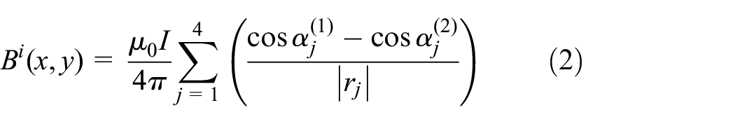
In Figure 3(a), the current that flows in the sending antenna can be described by a path composed of four segmented lines. Thus, the magnetic field at a point

where
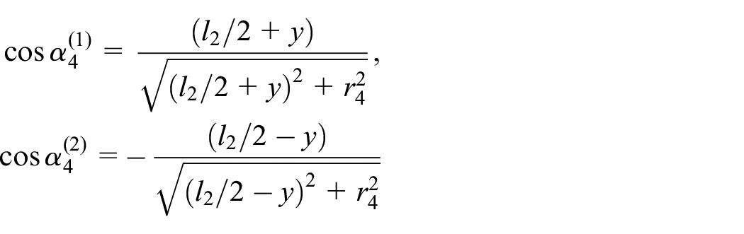
In Figure 3(b) and (c), we define geometrical parameters used to represent the magnetic field generated by x-directional and y-directional segmented currents, respectively. Meanwhile,
where


Due to the angle between
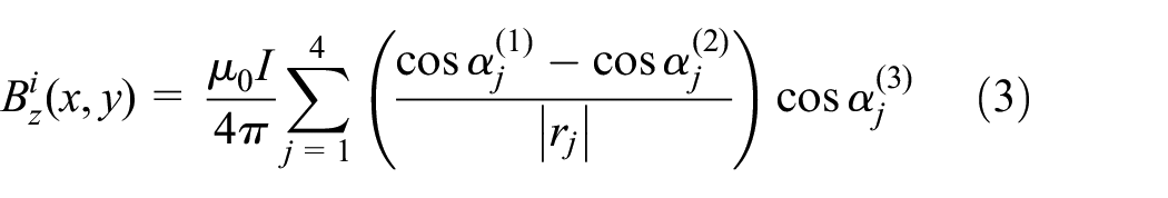
where


Induced voltage on the receiving antenna
The total magnetic flux passing through the receiving antenna located at

where

Hence, the mutual inductance between the sending antenna flowing the current

From (6), the induced voltage on the receiving antenna can be derived according to the Faraday law of electromagnetic induction. During a train passes, the induced electromotive force caused by the time-varying current is much larger than the motion electromotive force caused by the translation of the BTM antenna. 12 Hence, the induced voltage on the Balise receiving antenna is calculated as

where Qs is the quality factor of the Balise receiving antenna.
To simplify the analysis, the current that flows in the Balise sending antenna is defined as

where
According to the Lorentz Reciprocity Theorem, the induced voltage on the BTM receiving antenna of the up-link can be expressed as

where Qr is the quality factor of the BTM receiving antenna.
The output voltage of the down-link is the input of the energy conversion circuit model, which will be used in the following section. In addition, the input current of the uplink based on the data transmission circuit model will also be illustrated in the following section.
Equivalent circuit model
Energy conversion circuit model
As a specific passive Radio Frequency Identification (RFID) sensor in railway, the energy conversion circuit model of Balise usually include antenna, impedance matching circuit, rectifier, filter, regulator, energy storage device, or loads.20,21 As shown in Figure 4, the antenna is commonly modeled by a Thevenin equivalent voltage source

Energy conversion circuit model of Balise.
In Figure 4, the matching circuit can be tuned at low frequency
For analysis simplification, the circuits of rectifier, filter, regulator, and loads, circled by dotted line in Figure 4, are replaced by an equivalent resistance

where
According to Kirchhoff’s Voltage Law (KVL), the input voltage of rectifier circuit can be derived.

where
Then, the power consumed by
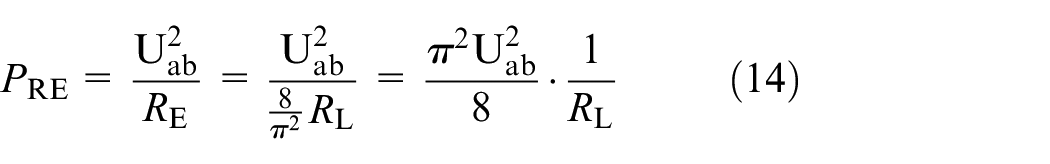
Where
Actually, the power calculated by (14) is consumed by

The input voltage of the regulator can be used as the direct current input resource of the following data transmission circuit model. According to (15), it is proved that the power supply of the data transmission circuit model is not only related to the impedance parameters of the energy conversion circuit, but also to the output voltage of the down-link magnetic field model.
Data transmission circuit model
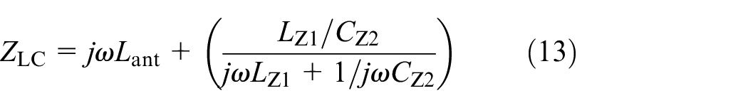
Figure 5 shows an equivalent circuit model of the data transmission module of the Balise derived by the Voltage Controlled Oscillator (VCO) principle. The oscillator uses an inductance-capacitance (LC) tank resonator and a capacitive cross-coupled pair (Q1, Q2) to generate negative resistance to compensate for the resistive LC tank loss.
25
The bias voltage

Data transmission circuit model of Balise.
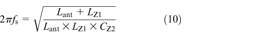
As a capacitor switched dual frequency LC VCO, 26 the output oscillation frequency of the Balise can be expressed as

In (16),


Where the operator “//” represents the series calculation of capacitance,
The output current of the up-link sending antenna can be obtained by the following equation.

where


As mentioned above, the variations of supply voltage (
Experiments and analysis
To verify and establish the models in Section “Model development” and obtain the model parameters for simulation, several experiments have been implemented, including I/O characteristics, Balise impedance, start-up behavior for the internal functionality test and magnetic field conformity, Up-link Signal Characteristics for the external interface test.
Experimental conditions
To study the magnetic field-circuit coupling model of railway Balise, the laboratory test set-ups recommended by the test specification of Balise transmission system (TB/T 3544-2018) were used for comparative verification. 5 Laboratory tests of the Balise was implemented with the laboratory test environment as shown in Figure 6.

Laboratory test environment of the Balise.
Due to different functionality and interface test items use the various test set-ups, Figure 6 only gives the main laboratory test tools and instruments for I/O characteristics test. The detailed equipment test connection diagram of different test items can find in the test specification of Balise transmission system.
Model parameters
For the magnetic field-circuit coupling model of the Balise, the magnetic field models were simulated by MATLAB, and the circuit models were simulated by Cadence PSpice. The coupling parameters between the magnetic field model and the circuit model can be transmitted by the collaborative simulation environment (SLPS) interface. The magnetic field model parameters for energy transmission and data transmission links are shown in Table 1. The mainly circuit model parameters of a commercial Balise are listed in Table 2.
Simulation parameters for magnetic-field model.

Only used for magnetic field conformity test.
Simulation parameters for circuit model.

Induction voltage of Balise energy reception antenna.
Model verification
According to the model parameters described above, several model validation experiments have been implemented with the experimental equipment shown in Figure 6. A reference loop (27 MHz impendence: 2.5 + 2.7j Ω, 4.23 MHz impendence: 0.5 + 0.2j Ω) was used to receive tele-powering signal or send up-link signal. A test antenna loop (200 mm × 200 mm) was used to send tele-powering signal. A test antenna loop (40 mm × 40 mm) was used to receive up-link signal. Two power meters (Frequency range: 100 kHz–6 GHz) were used to measure the power values of the reference loop and the test antenna.
Verification of magnetic field conformity
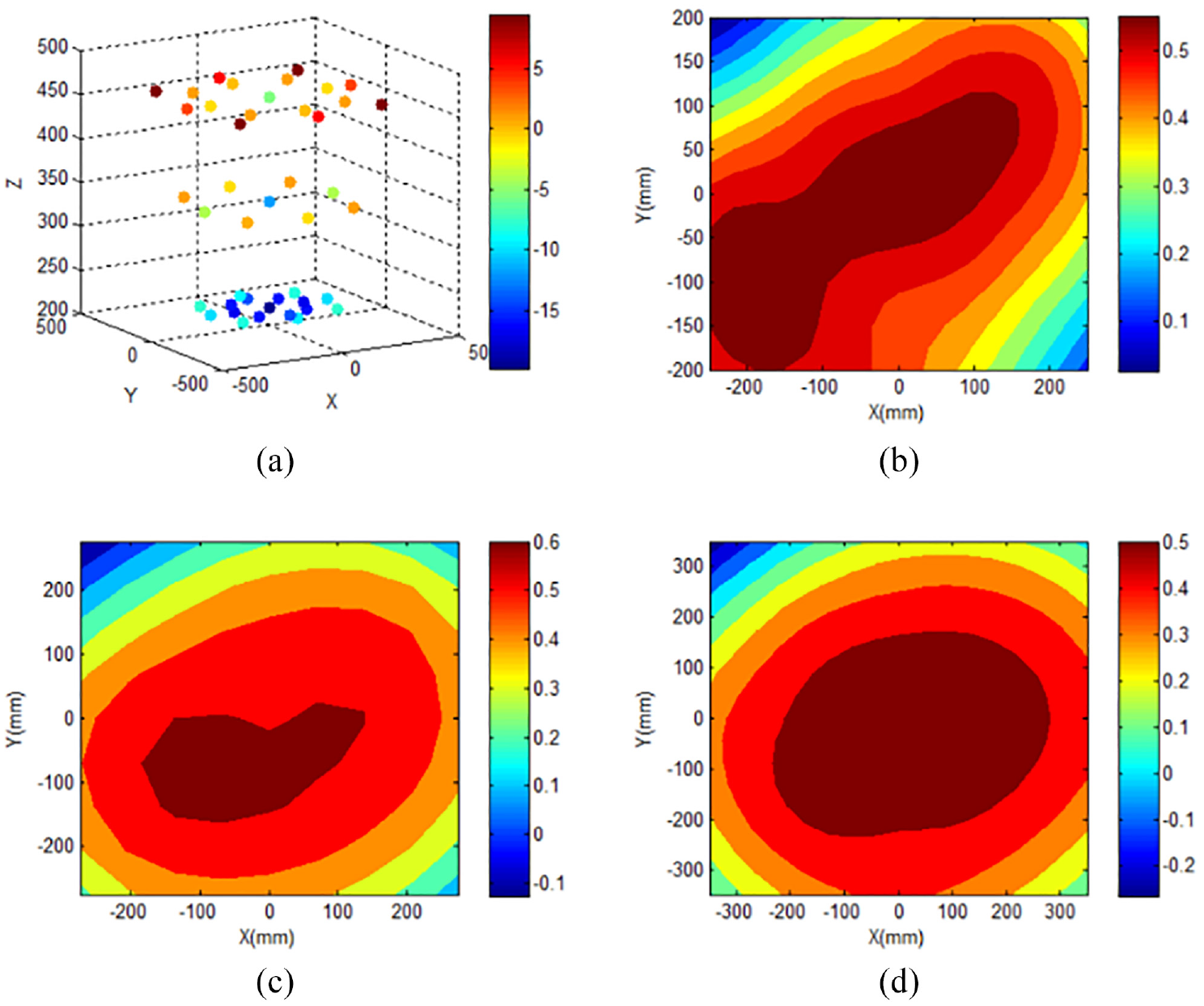
According to the model parameters described above, the magnetic field model of the Balise was verified by conducting several experiments. Firstly, the experimental results for the up-link signal magnetic field measured at an up-link signal current 37 mA through the reference loop are compared with the simulation results in Figure 7. The up-link signal magnetic field is obtained from 43 measurement points recommended by the test specification of Balise transmission system. The coordinate (x, y, z) is the spatial position of the reference loop relative to the test antenna loop. The comparison of the results revealed fairly good agreement between the simulated results and the experimental data. The maximum error of the simulated magnetic field power, which was 1.5 dB, was observed at the measurement point (x = −300 mm, y = −300 mm, z = 460 mm). When z was equal to 220, 340, 460 mm, the average error of simulation measurement points was 0.29, 0.65, 0.87 dB respectively. The simulation values of the up-link signal magnetic field measurement points are larger than the experimental values, and the simulation error increases with the distance between the measurement point and the signal source. The slight mismatch was observed at the distance far away from the signal source, potentially due to the accuracy of the magnetic field model.

Magnetic field distribution and simulation error of up-link signal: (a) distribution of the experimental results; contour map of the simulation error at: (b) z = 220 mm, (c) z = 340 mm, and (d) z = 460 mm.
Second, the simulation results of tele-powering signal magnetic field are verified by magnetic field conformity experiments and the reference loop need obtain a flux level of 7.7 nVs. The measure power value is proportional to the square of the current through the reference loop, and this ratio is 0.0025, which is obtained by experimental fitting. As shown in Figure 8, the simulation results are consistent with the experimental results. The maximum error and average error of the simulation measurement point were 0.59 and 0.41 dB, respectively. Magnetic field model is more accurate for tele-powering signal simulation than up-link signal simulation.
Magnetic field distribution and simulation error of tele-powering signal: (a) distribution of the experimental results; contour map of the simulation error at: (b) z = 220 mm, (c) z = 340 mm, and (d) z = 460 mm.
Moreover, the reference loop is replaced by a commercial Balise for magnetic field conformity test, and the absolute difference between the reference loop and the real Balise, the reference loop and the simulation Balise are compared as shown in Table 3.
Comparison between the experimental and the simulated Balise.
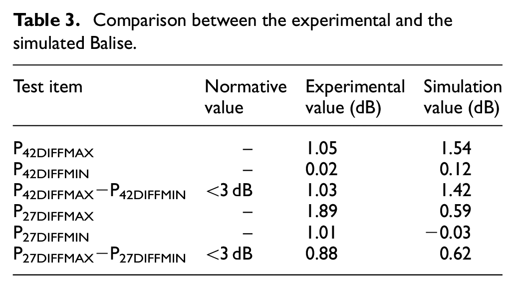
In the table, the value P27DIFF reflects the absolute difference of tele-powering signal magnetic field conformity, and the value P42DIFF reflects the absolute difference of up-link signal magnetic field conformity. As shown in Table 3, the experimental and simulation values meet the requirements of the magnetic field consistency specification of the transponder, and the magnetic field model is verified of compliance with the mandatory requirements in the test specification of Balise transmission system.
Verification of I/O characteristics
Three commercial Balises were used as examples to verify the I/O characteristics of the magnetics field-circuit coupling model. The experimental and simulation results of I/O characteristics are compared in Figure 9. The upper and lower limits are mainly related to the intrinsic cross-talk protection and detection of the Balise respectively.

Comparison between the experimental and the simulated I/O characteristics.
In Figure 9, Balise 1 and Balise 2 are Balise produced in different batches from the same manufacturer, while Balise 3 is provided by different manufacturers, and the simulation Balise is built by the magnetic field-circuit coupling model. Compared with the flux in the saturated region of different Balise response curves, the received magnetic flux of each type of Balise enters the saturated region after reaching 6.92 nVs. When the magnetic flux in the saturated region increases by 1 dB, the response of the Balise decreases by less than 0.1 dB. Compared with Balise 1, the deviations of the output current in the saturation region of the response curve of Balise 2, Balise 3, and the simulated Balise are −2, −15, and +42 mA, respectively.
From Figure 9, different design circuits and circuit parameters can produce different Input-to-output transfer characteristics for Balise. However, the response curves of all tested real Balise and simulated Balise are within the upper and lower limits specified in the non-shadow area in the figure, which is verified of compliance with the mandatory requirements of I/O characteristics in TB/T 3544-2018.
Simulation test analysis
To further verify and analysis the proposed model, several functionality and interface test cases were further studied below. The Balise impedance, as a test item of internal functional characteristics, was also used to analyze the transmission characteristics of the down-link interface. The start-up behavior test was used to analyze the internal function of the Balise, and the up-link signal characteristics test were used to analyze the transmission characteristics of the up-link interface.
Balise impedance test analysis
Several simulation cases have been implemented with model parameters in Tables 1 and 2 to analyze the test specification compliance and dynamic position effects of Balise impedance, including the Balise impedance at the Tele-powering magnetic fluxes of unsaturated region, saturated region, and test region, and the Balise impedance with different relative position. The representative simulation results are shown in Table 4. The comparison results of dynamic position effect based on equivalent impedance model and magnetic field-circuit coupling model are shown in Figure 10.
Simulation results of Balise impedance.


Comparison results of dynamic position effects: (a) equivalent impedance model and (b) magnetic field circuit coupling model.
The simulation results conducted in the test specification compliance are discussed and analyzed here to better analyze the impedance non-constant caused by tele-powering magnetic flux inconsistency, as shown in Table 4. In specification test region, all the simulation values at the Tele-powering magnetic fluxes of 110, 115, and 130 nVs shows the compliance of the proposed model with the impedance requirements of the test specification. The saturated region and specification test region show that the Balise impedance slightly positively correlates with the Tele-powering magnetic flux, because within a certain magnetic flux range, a higher magnetic flux increases the induced voltage of the Balise and generates a higher current in the energy reception antenna, which enhances the influence on the activation antenna and forms a higher Balise impedance. In addition, the unsaturated region shows a slight fluctuation of Balise impedance, which is not conducive to the significance analysis of dynamic position effect. The Balise impedance analysis should be recommended in the saturated region.
Comparative analysis of Figure 10(a) and (b) shows the maximum Balise impedance decreased due to increase of absolute horizontal distance and relative height, while the envelope of Balise impedance in saturated region appears to be affected by the dynamic position. In addition, the simulation conclusion of dynamic position effect based on the magnetic field-circuit coupling model are consistent with the previous work based on the equivalent impedance model. 17 Compared with the equivalent impedance model, the magnetic field-circuit coupling model increases the envelope width of saturated region from 0.24 to 0.4 m when h = 0.22 m, by 67%, and the analysis height of saturated region from 0.248 to 0.314 m when X = 0 m, by 27%. It proves that the proposed coupling model for simulating the dynamic position effect is feasible and acceptable in the Balise impedance analysis.
Start-up behavior test analysis
The start-up behavior of the simulation Balise based on the magnetic field-circuit coupling model under different magnetic fluxes was measured. The corresponding start-up time, output current, and input current were obtained as shown in Figure 11. The start-up time is a test item required by the internal functionality test, and the input current and output current obtained by simulation model can also be used to analyze the internal behavior of the simulation Balise.

Start-up behavior of the simulation Balise.
The results show that the start-up time of the simulation Balise decreases with increasing magnetic flux. The start-up time of the simulation Balise at
Up-link signal characteristics test analysis
Based on the proposed model and parameters described above, the up-link signal characteristics of Balise at the received magnetic flux of 19.51 nVs has been analyzed. The zero-crossing detection method is used to demodulate 1500 bits uplink signal. The duration of the modulated bits of upper-side frequency and lower-side frequency is 44.24 us. The center frequency and frequency offset test time window are selected as 50 bits, and the fixed sliding window in the amplitude jitter stability region is 300 bits. The numerical simulation results of test specification compliance are shown in Table 5.
Test specification compliance simulation results of up-link signal characteristics.
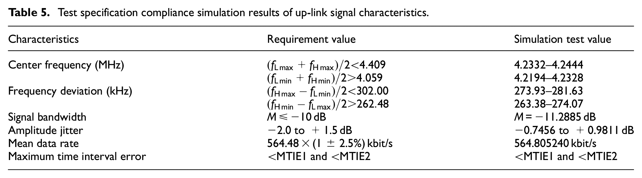
In Table 5, all the up-link signal characteristics of the simulation Balise compliance with the requirements of the test specification, and the simulation results of MTIE, center frequency, frequency deviation, and amplitude jitter are interval fluctuations, not constants. This is consistent with the actual situation, and shows that the simulation Balise model with physical circuit model is correct and can effectively reflect the physical characteristics of the Balise. To analyze the interval fluctuation results of uplink signal characteristics, the comparative analyses with the up-link signal characteristics at the received magnetic flux of 5.5 nVs have been made. The comparison of the interval fluctuation results is shown in Figures 12 to 14.

Simulation test results of: (a) MTIE1 and (b) MTIE2.
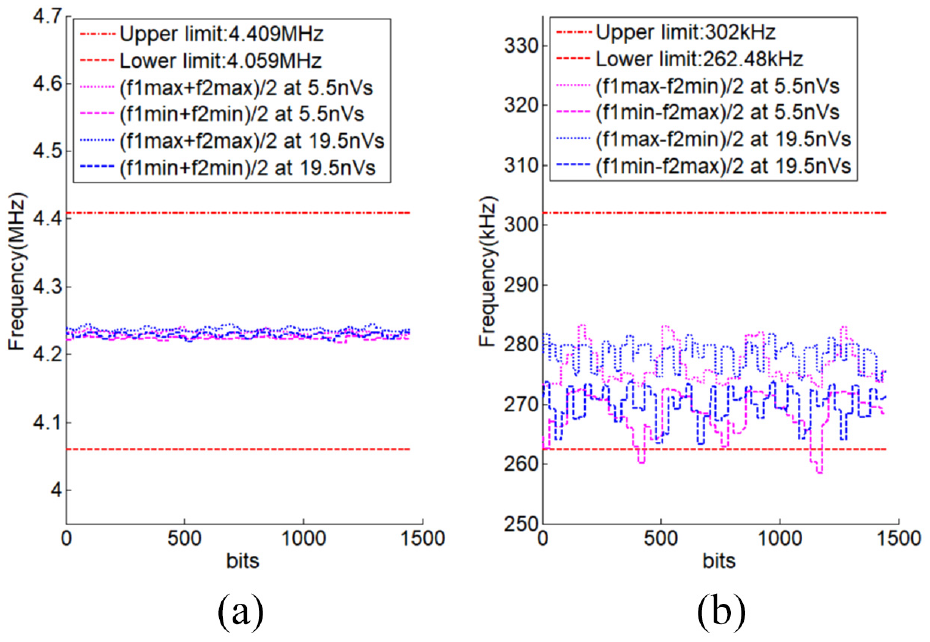
Simulation test results of: (a) center frequency and (b) frequency deviation.

Simulation test results of amplitude jitter.
In Figure 12, the MTIE1 curve is steeper than the MTIE2 curve, which is attributed to the increase of the number of bits and proportionally increases the time interval error between the actual test data rate and the ideal data rate. In addition, the average values of MTIE1 and MTIE2 in the saturated region are slightly smaller than those in the unsaturated region when the receiving magnetic flux is 19.5 and 5.5 nVs, respectively. The standard deviations of MTIE1 and MTIE2 in the saturated region are 1.1e-7 and 9.3e-8, respectively, which are slightly less than 1.9e-7 and 9.7e-7 in unsaturated zone. Thus, the up-link signal in the saturated region has better frequency characteristics and lower amplitude jitter than that in the unsaturated region at the same model parameters, as shown in Figures 13 and 14.
According to the center frequency curve in Figure 13(a), the average values of
Conclusions
For the scientific and accurate modeling and analysis of the performance of a new designed Balise, a more realistic and effective model coupling the magnetic field and equivalent circuit was developed. Several experiments were conducted to verify the model. Several functionality and interface tests of Balise were studied with main conclusions summarized below.
Compared with the equivalent impedance model, the proposed model more realistically and comprehensively describes the interface coupling effects and internal physical characteristics of the Balise, which can make the new product performance analysis more convenient to better carry out the optimal design.
The functionality test results of the Balise are not only related to the electrical parameters of the physical circuit model, but also to the inducted voltage of the down-link magnetic field. Thus, it is more credible to verify the physical function availability of the Balise under different magnetic field conditions.
The Balise impedance test of down-link interface under different magnetic field conditions can obtain more dynamic characteristics of the Balise, which can provide a new detection parameter for the comprehensive inspection train. The characteristics of the up-link interface are slightly affected by the down-link magnetic field. Therefore, when analyzing the physical characteristics of the Balise based on the up-link signal characteristics, the influence of the down-link magnetic field on the up-link interface should also be considered.
Based on this model, the obtained parameters of all simulation tests, including magnetic field distribution, I/O characteristics, impedance, start-up behavior, and signal characteristics, can provide data support for optimal design and digital management of the Balise. For dynamic test applications, there are still some further studies to be done, including the construction of more efficient hybrid model based on real data and improvement of the analysis method.
Footnotes
Handling Editor: Chenhui Liang
Declaration of conflicting interests
The author(s) declared no potential conflicts of interest with respect to the research, authorship, and/or publication of this article.
Funding
The author(s) disclosed receipt of the following financial support for the research, authorship, and/or publication of this article: This research was supported by the National Natural Science Foundation of China (52102472, U2268206, T2222015), Fundamental Research Funds for the Central Universities (2022JBMC006).