
Abstract
This paper presents a novel approach to building a vertical wall-climbing robot using the vacuum method and the internal contact model. By leveraging advanced 3D printing technology, the proposed robot model addresses three key challenges encountered in previous studies: achieving high traction force for smooth and efficient movement, ensuring low roughness and fast shifting capability, and minimizing production costs for mass deployment. The vacuum suction method employs an air compressor to generate suction force, enabling the robot to ascend walls vertically. This process significantly increases airflow velocity, creating a low-pressure area that enhances adhesion to the surface. The utilization of 3D printing technology allows for the creation of the robot’s bodywork and essential components, facilitating adjustments in the mechanical system design. The developed robot is well-suited for inspecting and maintaining hazardous areas in tall buildings and conducting surveillance in factory settings. Moreover, it proves valuable for cleaning and monitoring slippery surfaces with minimal roughness. The research findings demonstrate that incorporating 3D printing technology in the design and construction of wall-climbing robots has successfully achieved the desired speed and grip capabilities.
Keywords
Introduction
Large structures are being built taller and taller as the construction industry rapidly develops, particularly in major cities around the world. Maintaining these structures requires a significant number of personnel to clean, monitor, and ensure that everything is functioning properly.1,2 However, many of the areas that need monitoring are located in dangerous, high-elevation or hard-to-reach corners that are inaccessible to humans. To address these challenges, researchers have proposed various solutions such as spider robots, snake robots, and wall-climbing robots. As a result, wall-climbing robots, like the robot car that runs on walls, have become a topic of great interest in construction monitoring research.3,4 Wall-climbing robots are among the advanced robotic technologies that emerged in the 1960s as shown in Figure 1.

The development history of the wall-climbing robot and the research orientation of the manuscript.
This group of robots is capable of climbing and moving on vertical or horizontal surfaces, and they can perform various tasks under human control. As a result, this group of robots has garnered significant attention from researchers in the field of robotics. Wall-climbing robots have expanded and been categorized into different groups, such as negative pressure suction robots, magnetic adhesion robots, rotor-based robots, and bio-inspired wall-climbing robots, which have emerged in recent years.
- The robot car concept is extremely useful in monitoring and tracking changes in hazardous parts of the building. However, researching, engineering, and manufacturing mobile robots capable of climbing and hanging on walls and ceilings is difficult since the robot must be able to grip when it encounters walls with low surface roughness, excessive slip, fissures, or gaps between wall regions. Many prior studies suggest that in order to tackle this challenge, the movement and adhesive capabilities of the robot on the wall must be determined. Many studies have addressed different types of robot vehicle movement. For example, Kim et al., 5 Bach et al., 6 and Tavakoli et al. 7 have studied and developed a robot that moves on the wall utilizing cables in conjunction with a variety of methods to assure suction and adhesion forces in slick and slippery working situations. Furthermore, the preceding studies take into account the model’s compactness while functioning, as well as its ability to clean the environment up to 88.9%. 5 According to the findings of the preceding investigations, the advantages of the vehicle robot model are that it can perform some necessary functions, and the robots can remain securely in specific environments. However, the drawback of these studies is that when the suction force is not high, the model’s capacity is usually less than 45 N.6,7 As a result, these models cannot be used in situations with heights greater than 20 m. Furthermore, the vehicle’s capacity to work in slick working settings with limited adhesion has not been completely evaluated.
- The mechanical drive system is a significant and decisive aspect in the success of the vertical wall climbing robot car model. Following the results of Hu et al., 8 crawler transmission is used in wall climbing robot research. The robot model from the study can move on a cylindrical wall with a radius of curvature of 3 m and resist a load of 75 kg using this motion transmitter. This could be the model that can carry a heavy load at the moment. The downside of the chain transmission used in this study is that it is ineffective when the robot travels because the movement speed is low, and the adhesion of the robot car to the wall is insufficient for slick environments like glass or marble. Furthermore, the mechanical chain drive system is noisy and cannot move up high walls. As a result, the model from this study’s efficacy cannot fulfill the needs and operating conditions. These findings are consistent with those of Nishi, 9 Guo et al., 10 Fu et al., 11 and Ma et al. 12 for robot models that use chain transmission as the motion transmission mechanism.
- It is probable that the reason most trials have failed is that the bonding process between the robot car and the surface has not satisfied the requirements specified. Various options have been used, including suction cup crawler adhesion,8–15 magnetic adhesion,16–19 and suction cup adhesion16,18,20,21 as shown in Figure 2. Furthermore, we utilized a dry adhesive approach to develop a wall-climbing robot that can move at a speed of 13.3 m/s and steer stably at a narrower angle of 55° for 5 s, as reported by Liu et al. 22 and Xu et al. 23 However, the wall-climbing robot developed in this study has a highly complex structure and a high production cost, making it unsuitable for completing the prescribed duties unless sufficient funding is available. According to Yi et al., 24 a vacuum approach was used to develop a robot system. However, if the suction force is insufficient, the robot system may not be able to function effectively in high and smooth environments, and the results may not meet the problem’s requirements.

Some cleaning and monitoring methods for high-rise buildings.
The motion transmission system in wall-climbing robot models is crucial and the most important component in the model. Several motion transmission systems have been studied, including (as shown in Figure 3): chain transmission system, belt transmission system, cable transmission system, suction-based system, vacuum-based system, etc. However, robots often face numerous challenges during assembly due to the intricate process of precisely fabricating the components. Advanced manufacturing technologies and rapid prototyping techniques have brought about highly advantageous solutions for the fabrication process of wall-climbing robot models, offering both accuracy and cost-effectiveness.

Some models of vehicle mechanical motion transmission on vertical wall.
Currently, 3D printing technology is making significant contributions to various professions, especially mechanical engineering.25–27 Instead of printing an image, 3D printing is used to produce 3D objects that can be handled, seen, and held. This technology allows us to turn seemingly complex design ideas into simple tasks that can be successfully completed by everyone.28–30 In 3D printing, the details of an object are printed layer by layer, and these layers are then bonded together using additives, temperature, or light. The ink used to create the product is the material itself. This technology has revolutionized the restoration, manufacture, and improvement of objects ranging from simple to sophisticated models, not only in Vietnam but all around the world. With the technique shown in Figure 2, 3D printing technology has a wide range of applications in almost all industries and assists businesses in swiftly and efficiently bringing their ideas and projects to life. The use of 3D printing technology for manufacturing mechanical parts is widely adopted in various industries, such as automotive, aviation, and military, as depicted in Figure 4.

3D printing process in real life.
This study proposes the use of 3D printing technology by PLA (Polylactic Acid) to design, model, and build a vehicle robot with a simple structure and low manufacturing costs to serve in monitoring and cleaning human substitutes in dangerous high altitude positions. Because PLA is one of the popular 3D printing filaments in the FDM (Fused Deposition Modeling) market. This type of filament has a relatively low cost, is easy to print with, and comes in a wide range of vibrant colors. PLA offers several advantages over other petroleum-based plastics, such as ABS (Acrylonitrile Butadiene Styrene) or PVA (Polyvinyl Alcohol). This manuscript addresses the shortcomings of prior studies as the robot car model is capable of moving vertically at high speed using the vacuum approach. Furthermore, the robot’s high stickiness is beneficial because it can be used in various dynamic settings. The findings of this study suggest that daily deployment of robots can significantly reduce the cost of monitoring and cleaning tall buildings while fully eliminating the risk to the worker in hazardous situations.
Theoretical basis
Using Bernoulli’s equation for continuous gas flow
Surveying the airflow moving inside a closed air duct, the Bernoulli process for the flow of air moving between two shear surfaces is expressed as equation (1)31–33 :

Where: p– Static pressure [N/m2];

However, in practice when the robot climbs the wall usually the straws do not have much deviation in the height of the two points, equation (2) is rewritten by equation (3):

Because velocity v and pressure p are inversely related, the quicker the velocity increases, the lower the pressure in the tube, ensuring that the right side of equation (3) is always constant. As a result, we can see that an air suction machine is required to create a vacuum in order to keep the pressure column in him equally absorbed when the robot changes height, moves rapidly, and travels in a slippery terrain with minimal grip.
Data and design requirements
The design material chosen for this study was created entirely using 3D printing technology and the additive printing method.34–36 This method allows items to have the appropriate hardness after printing to withstand the compressed air pressure of gases and prevent distortion when the model is hoisted. Additionally, the material used in 3D printing technology is basic, easy to find, simple to process, and, most importantly, low-cost. To meet these criteria, researchers used 3D printing technology with 10% hollowness to create a robot car model that runs on a vertical wall using vacuum. Table 1 and Figure 5 show the material characteristics and qualities after using 3D printing technology.
Specifications of 3D printed plastic.


Some parts of a 3D-printed robot car model.
Traditional transmission of movement of wall climbing robots from research
Standard Wheels
Standard wheels are typically circular and come in predefined sizes. They rotate around the axle and can be steered in different directions. Figure 6 shows the design and function of different types of standard wheels. Figure 6(a) is a fixed wheel with only one degree of freedom, while Figure 6(b) to (d) have two degrees of freedom and act as rudders to adjust the direction of the robot’s movement. The selection of a particular wheel model depends on the direction of the investigation and how the robot car is driven. The steering shaft and wheel axle are always perpendicular to each other and lie in the same plane, as shown in Figure 6(b). Figure 6(c) shows a lateral offset wheel, in which the steering shaft is not in the wheel plane but is perpendicular to the wheel axle in the same plane. Figure 6(d) shows a castor wheel with a steering shaft that is not in the same plane as the wheel shaft. This type of wheel is more suitable for cases of rear steering, as it allows for more sensitive direction changes and can redirect the robot more quickly.

Standard wheel forms commonly used for models: (a) fixed, (b) steered, (c) lateral offset, and (d) castor wheel.
Omnidirectional wheels
Figure 7 shows the different possibilities that were used to construct the wheel model for this study. When a standard fixed wheel moves, it can only move in one direction and cannot change direction, whereas omnidirectional wheels can change direction without requiring a steering system, even when fixed. This is due to the small wheels on the rims. The aim of this study is to control vehicle models moving on a range of terrains with varying adhesions, so the wheels must always be omnidirectional. The wheels that were designed for this study are shown in Figure 8.

Some wheel models used.

Representation of omnidirectional wheel styles.
Analysis and selection of the guide system for wall climbing robots
The typical robot vehicle model has four wheels, with two active wheels at the rear and two steering wheels at the front. The model is illustrated in Figure 7, while the wheel movement control diagram is presented in Figure 9a–f. These figures are used to evaluate and select the optimal lead wheel system for wall-climbing robots, as per the scope of this study.
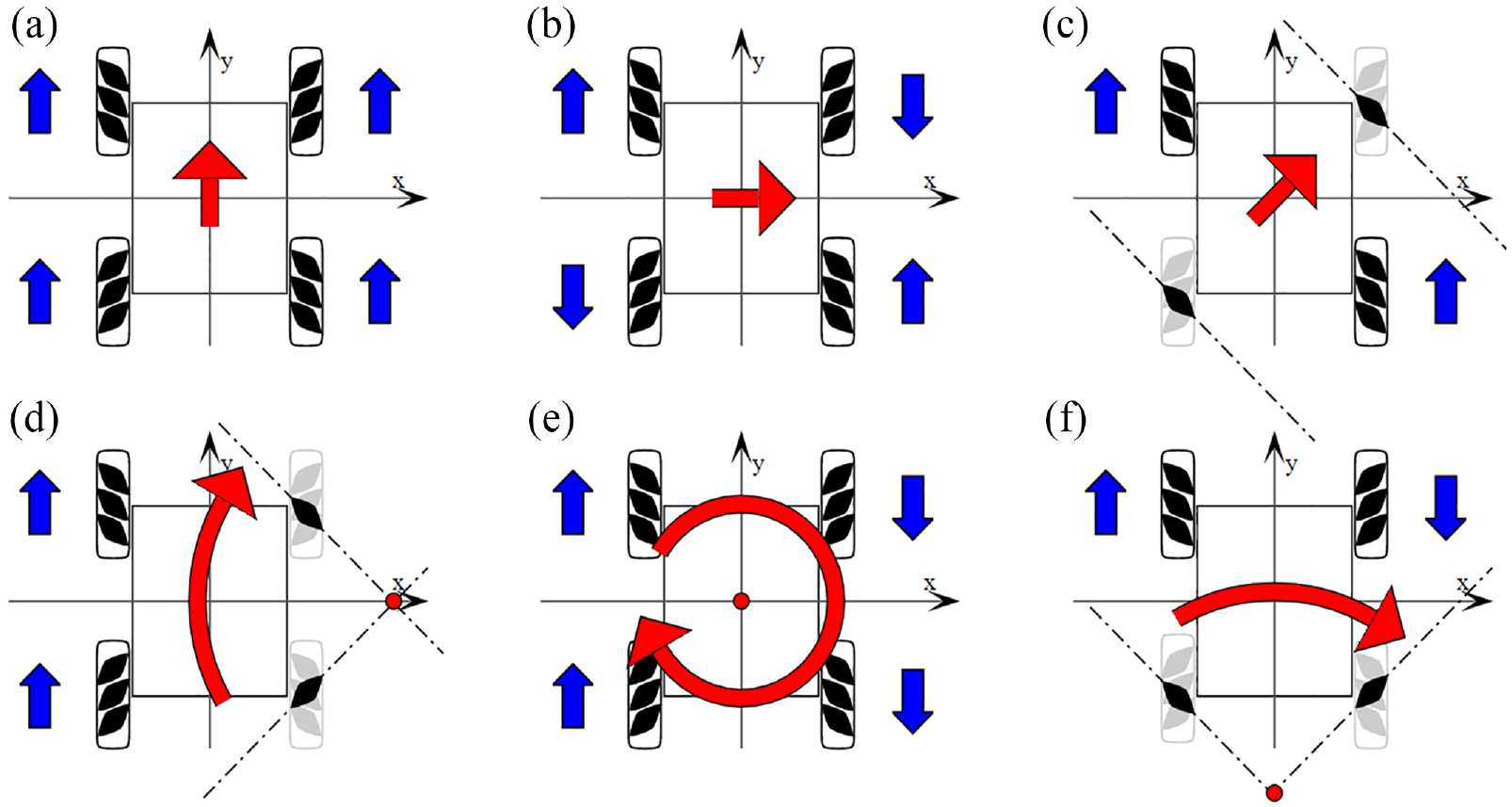
Assumption of a conductive wheel system for a vehicle robot.
With this design assumption, the design can evaluate and select a suitable guiding system for the wall-climbing robot. Figure 10 illustrates the force modeling and evaluation while the robot is climbing a wall, where P represents the force of the car in the vertical state, K is the air barrier, which depends on the height at which the robot operates, Pf is the rolling bumper of the car on the wall, N represents the jet of the wall acting on the car during operation, Fh is the suction force of the vacuum system, and Fb is the grip of the wheel on the wall.

Wall climbing force analysis model.
The equilibrium equation is obtained when the car is capable of staying on a vertical wall, which satisfies equation as shown in equation (4):

According to the force balance equations system in equation (4), increasing either the coefficient of friction or the attraction value would allow for a larger payload in the robot vehicle design. In other words, by increasing one or both of these parameters, the robot would be able to carry more weight. The goal of this section is to select a drive wheel system capable of propelling the robot vehicle. Therefore, the coefficient of friction will be considered during actual operation. The coefficient of friction is known to be influenced by the surface material, surface smoothness, and contact time, but not affected by the contact area, contact pressure, and relative velocity of motion between the two surfaces since this model employs vacuum suction. Additionally, vertical wall climbing robots require a flexible and fast steering system that can quickly change direction, unlike conventional cars. It should be noted that the robot needs to hold steady in position and make quick turns to reach corners and edges of the wall. Based on this research, the author chooses a two-wheel active steering system located at the rear and two rudders located at the front, as illustrated in Figure 11.

Wall climbing robot wheel layout diagram.
Choosing an actuator for the wheel axle
If a vertical wall climbing robot needs to stop suddenly, its inertia can cause the entire weight of the robot to fall. Therefore, the robot needs to be able to apply brakes to prevent a sudden fall. To address this issue, the paper proposes two solutions: first, using the controller to stabilize the position of the drive motor; and second, using a screwdriver for driving. To simplify the model and reduce experimental costs, the study employs a screw wheel transmission, which has a high gear ratio and excellent self-braking ability, as shown in Figure 12.

Screw transmission.
With the selection of screw wheel transmission for the robot wheel axle, the manuscript has developed a preliminary design model for the robot body as shown in Figure 13:

Robot car model from the study.
Proposed model from the manuscript
Computational model for wall-climbing robot vehicles
From model as shown in Figure 14, we have:

Wall climbing zone force analysis diagram.
P is the force, K is the air barrier, Pf is a rolling bumper, N is a jet, Mtd is the name of the motor that drives the wheel axle, Ml is the torque produced by rolling friction, Fh is a suction device, Fb≈Fms are the forces of adhesion and approximately equal to the frictional force.
The system of force balance equations as in equation (5) is derived from the model shown in Figure 14:
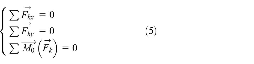
Calculating the system of equation (5) we get the result as equation (6)


During the design calculation, the parameters that are known include:
The gravitational acceleration is g = 9.8 [m/s2], the expected robot mass is m = 2 [kg], the sliding coefficient of friction is μ = 0.75, and the rolling coefficient of friction is f = 0.015. By substituting these parameters into equation (6), we obtain:

For the car to overcome drag and move:

Gravity applied to the vehicle:

Rolling Resistance:

With f as the rolling resistance coefficient, the study will look at the surface of the road and concrete in smooth, dry and clean conditions, corresponding to f = 0.012
Air resistance:

Where: c.ρ = 0.15 is the air resistance coefficient, D = 0.1 × 0.3 = 3.10−2m2 is the frontal bumper area, v is speed with v = 3 [km/h] =0.833 [m/s]. So we have the total drag calculated as the sum (9,10,1 1): =>

Attachment Force:

Where: Z is the force acting on the car; φ is the number of clings. Considering concrete, asphalt, glass, granite in a clean and dry state, we have a cling factor: φ = 0.7
Conditions for the car to overcome resistance and move:

Power supply to a 10 V motor
The wheel motor has
So tangential traction can give the car

Thus qualified:
In case the car moves slowly until it stops completely

That

In case the car moves quickly and evenly
If the Fk force is increased
This means:

Transmission efficiency:

Where: ηkn is the capacity of the mobile shaft coupling; ηot is the power of a pair of sliding drives; ηBV is the power of a pair of self-braking screw transmissions. Choosing the speed of wheel rotation, the study expected the robot design to climb the wall at a speed of about 0.833 [m/s]. This is the velocity of the robot body and also the velocity of the wheel. So V = 0.833 [m/s]. From the engine parameters F, V, η we calculate the engine power as:

Calculate the number of revolutions and torque for the engine to reach a speed of V = 0.05 [m/s]. The angular velocity of the wheel is expressed as equation (21):

Wheel revolutions:

The gear ratio for the screw transmission is:

Calculation of engine revolutions:

Calculation of torque of the motor shaft:

Design model
After performing calculations, the study formed a design model as shown in Figure 15. The design results, after assembling the suction parts and mechanisms, are as follows:

Chassis after installing the suction mechanism.
Simulation results
To simulate the operation of the vacuum mechanism while the robot is stationary against a vertical wall, we use the simulation to calculate the airflow velocity in the air chamber, the airflow rate, the pressure of the airflow acting on the chassis, and the flow of air around the chassis. The following theoretical data is provided for the simulation: Propeller revolutions: n = 22,000 [v/ph] Atmospheric pressure: Pa = 1 bar at 250C
Simulation of the velocity of the airflow when operating on a vertical wall
The results in Figure 16 reveal that the external airflow acting on the robot car during operation consists of the following:
− The airflow outside the car enters the chassis from the surroundings. In variable altitude contexts, the model proposed in this study is more stable compared to others. As the tire model is entirely developed through 3D printing technology, the airflow direction from the outside smoothly creeps into the distance between the chassis and the wall, enabling the airflow to pass through the areas and change its area smoothly without generating turbulent flow.
− Outside the car, there is no gas flow reaching the maximum velocity. The gas flow mainly moves at a velocity range of v = 0.018 [m/s] to v = 89.33 [m/s]. The highest velocities recorded outside were at the edge of the frame between v = 89.33 [m/s] to v = 178.6 [m/s]. Despite this velocity acting on the car model, it still ensures a safe working mode.

Results of airflow simulation seen from outside the frame.
The airflow burner inside the chassis acting on the vertical wall shown in Figure 17 can be described as follows:
− The airflow from the outside of the chassis gradually becomes more turbulent as it approaches the fan, and primarily flows along the chassis toward the output. Due to the vacuum environment in which the research model operates, the airflow exerts pressure on the frame. The gas flow velocity quickly reaches its maximum near the surface.
− Airflow velocities vary from approximately v = 178 [m/s] to v = 267.9 [m/s] for most of the pathway, and sometimes peak at vmax = 357.2 [m/s] near the surface.

Results of airflow simulation inside the chassis.
The results of the simulation of airflow when the car moves on the wall are shown in Figure 18, with the following observations:
− The airflow reaches a high speed when it impacts perpendicular to the back of the chassis, primarily in a cascading flow with the speed gradually increasing from the second half of the chassis. This may be the primary reason why the robot loses its suction and falls off the wall during operation. In particular, the maximum velocity of the gas flow is approximately v ≈ 357.2 [m/s], and the smallest speed of the gas flow is about v ≈ 0.0736 [m/s].
− The highest velocity is due to the action of the suction mechanism, which creates a rapid displacement of the airflow from bottom to top and from front to back. Therefore, this is an advantage when designing a robot car model using the vacuum method. It allows the car model to move quickly during operation while having the ability to change direction continuously. Figure 18 shows the simulation of the robot’s airflow seen from the bottom up

Simulate fluid flow when the vehicle is moving.
The evaluation model as shown in Figure 19 includes:
− The airflow velocity begins to increase at the edge of the robot, when the suction force of the suction mechanism is greatly affected and the airflow gradually increases until the propeller. Upon entering the robot frame, the flow gradually changes from stratospheric to tangled flow, peaking at the tangled node near the suction mechanism.
− Airflow velocities vary rapidly from about v = 178.6 [m/s] to v = 279.9 [m/s] for most of the road where the robot operates. This velocity range is quite stable and similar for different environments, sometimes reaching a maximum velocity vmax = 357.2 [m/s] near the outlet surface.

Simulation of the robot’s airflow seen from the bottom up.
Pressure simulation of robot vehicles
Pressure inside and outside the frame as the robot moves
The pressure simulation results of the vehicle robot model are shown in Figure 20. The results must show the pressure difference in and out of the air chamber affecting the ability to adhere to the robot frame, as well as whether the pressure affects the vehicle model’s shell and the process of the frame clinging to the wall.

Pressure model of a robotic chassis: (a) pressure difference inside and outside the robotic frame and (b) pressure inside the robotic frame.
From the results from Figure 20 it shows:
− The pressure outside the frame is higher than the pressure inside the frame. From this pressure difference, the largest point of the out-of-frame pressure difference with in the frame falls around P ≈ 83,000 Pa, the smallest point of the out-of-frame pressure difference with in the frame falls around P ≈ 41,500 Pa.
− The part near the rear robot body where the pressure falls is about P ≈ 80.655 Pa, which is much different from the part toward the rear of the robot body, proves that the rear of the car has a tangled flow, which helps push the robot forward
Simulate the pressure distribution on the chassis
− The pressure applied to the frame mainly falls between P = 84.810 Pa to P = 101,400 Pa located on the front and hip of the frame. Many of the pressure frame plane serial positions are smaller than the frame surfaces, ranging from P = −64.610 Pa to P = −68.210 Pa as shown in Figure 21
− The smaller pressures noted are located in the positions behind the frame surface, falling between P = −64.610 Pa to P = 68.210 Pa. In general, the pressure applied is relatively uniform on the surface in front of the robotic frame, gradually decreasing toward the back of the frame as shown in Figure 22.

Results of simulation of the frame pressure subjected to the upper side.

Simulation of the frame pressure subjected to the underside of the frame.
Simulate the durability of the frame when the suction motor pressure acts on the robot frame while moving. When the robot is in operation, the pressure of the suction mechanism and the airflow impact the frame as the robot moves, requiring the frame to have a specific level of durability.
Conclusion
− This study presents a design and construction plan for a vertical wall-climbing robot that utilizes a vacuum approach and an internal contact model. If you are interested in investing in and developing a practical solution for everyday life, consider the wall-climbing robot model. The use of wall-climbing robots offers significant economic benefits as it addresses the current labor shortage and eliminates hazardous tasks. The proposed vehicle robot model in this study incorporates advanced 3D printing technology to tackle three key unresolved issues from previous research: achieving a high suction grip for smooth movement on complex surfaces, implementing a fast transfer model with low surface roughness and high migration speed, and ensuring low production costs suitable for mass production.
− The vacuum approach involves the robot vehicle utilizing a vacuum system to draw in air from an air compressor, creating suction force against the wall, enabling the car to travel vertically. By increasing the airflow velocity, the pressure decreases, creating a low-pressure area that provides effective suction capability for the car to adhere to surfaces. 3D printing technology was utilized to fabricate the body and various essential components of the robot car model, allowing for ease of modifications in the mechanical system’s design. The robot cars developed in this study can be employed for inspection and maintenance of high-rise structures in hazardous areas, as well as monitoring factory premises. Additionally, the model is well-suited for cleaning and monitoring smooth environments with minimal surface roughness. The research findings demonstrate that 3D printed robots can be designed and constructed to fulfill the speed and gripping requirements of wall-climbing robots.
Footnotes
Handling Editor: Chenhui Liang
Author contributions
Viet-Hung. Pham: Conceptualization, Methodology, Software, Field study. Hoa-Cuc. Nguyen: Data curation, Writing-Original draft preparation. Bich-Ngoc. Mach: Visualization, Investigation, Writing-Reviewing and Editing. Ngoc-Duong. Nguyen: Software, Validation., Field study. Thanh Q Nguyen: Conceptualization, Methodology, Software, Field study.
Declaration of conflicting interests
The author(s) declared the following potential conflicts of interest with respect to the research, authorship, and/or publication of this article: This is to certify that to the best of authors knowledge, the content of this manuscript is original. The paper has not been submitted elsewhere nor has been published anywhere.
Authors confirm that the intellectual content of this paper is the original product of our work and all the assistance or funds from other sources have been acknowledged.
Funding
The author(s) disclosed receipt of the following financial support for the research, authorship, and/or publication of this article: This research is funded by Thu Dau Mot University, Binh Duong Province, Vietnam under grant number DT.22.1.007. This research was supported by AI to correct English mistakes, check grammar, and suggest new words because we come from countries where English is not a native language. However, the entire content of the research was developed by the research team.