
Abstract
The brake disc spindle of the electromechanical braking system will be accompanied by vibration unbalanced fault during the rotation operation, which will affect the braking performance of the brake system. In view of this phenomenon, based on the ensemble empirical mode decomposition algorithm and related energy operation theory, an offline purification program for the unbalanced axial trajectory of the spindle of electromechanical braking system are designed. Meanwhile, an online braking control feedback procedure for the axial trajectory are designed based on Cspace controller. Based on the designed program and braking theory, an experimental bench of the electro-mechanical braking system was set up, and experiments were conducted on the purification of the axial trajectory and the braking of the fault feedback respectively. The results show that the EEMD algorithm and the related energy operation theory can purify the unbalanced axial trajectory of the brake discs of the braking system and draw an ideal axial trajectory fault map; meanwhile, the experimental data of the fault feedback braking shows that the time required from the unbalanced fault monitoring to the completion of the braking process of the braking system is 1.278 s, which can effectively achieve the purpose of emergency braking in case of sudden failure. Through research, a new idea is provided for the development of electro-mechanical braking system fault detection and feedback.
Keywords
Introduction
Electro-mechanical braking system technology was first proposed in the field of aviation, and has since been studied more extensively in the automotive field, with the advantages of simple structure, small size, fast response time, and high control accuracy. The principle of electro-mechanical braking system is to convert the electrical signal directly into braking force output through the motor and reduction mechanism, eliminating the need for braking pipes in the whole system. It realizes the full electrification of the friction brake, completely free from the dependence on the braking medium, and completes the transformation from compressed air or hydraulic drive to electric drive. Compared to traditional air or hydraulic braking systems, the advantages of electro-mechanical braking systems include light weighting of the system, improved system control performance, reduced failure points and improved maintenance, improved energy efficiency and intelligence. Currently, new advanced aircraft such as the US Global Hawk UAV, F16 fighter jet, and Boeing 787 are all officially using electro-mechanical braking systems, and the widespread use of electro-mechanical braking systems on the next generation of aircraft has become a definite situation. Electro-mechanical braking systems are used in all types of transport and mining machinery. In transportation, there is a Chinese car brake Haitai company will electro-mechanical braking system used in urban rail transportation equipment. In mining machinery, electro-mechanical braking systems have been used in place of hydraulic disc brakes in the field of mine hoists. 1 Based on safety considerations, the use of electro-mechanical braking systems is inevitable without fault diagnosis, so the fault analysis of electro-mechanical braking systems cannot be ignored.
The brake disc spindle is the main component of the overall electro-mechanical braking system and is responsible for the subsequent braking process of the braking system. The shape of the trajectory can be used to visually represent the fault characteristics, and then timely feedback control can be taken to avoid the fault. Akhtar et al. 2 have studied the problem of high vibration on a gas turbine using Porter diagrams, axis trajectory diagrams, and axis centerline diagrams. Axial trajectory diagrams and shaft centerline diagrams examined rotor behavior, compared machines suffering from high vibration problems with normal machines, and identified resonance as the root cause of high vibration in gas turbines. Mingjun et al. 3 proposed a sparse algorithm to purify the simulated shaft trajectories affected by Gaussian white noise to verify the reliability of the algorithm in view of the characteristics of rotor shaft trajectories with clutter after synthesis. Zhang et al. 4 identified and classified the shaft trajectories of magnetic levitation bearing and rotor systems, and also used the Hu moment invariant algorithm to extract feature vectors from the shaft trajectories to identify faults, and through experimental The study concludes that it has higher accuracy and robustness in small sample classification. Belhocine et al.5–9 have conducted extensive research on the brake disc friction problem of mechanical parking disc brakes, making a predictive assessment of the braking performance of the braking system through finite element models, as well as a thermo-mechanical coupling analysis of the brake disc, seeking to provide an excellent rotor design to ensure good braking performance of the vehicle. These studies have shown that axial trajectories can effectively reflect the characteristics of rotor system failures, but the axial trajectory signal is inevitably contaminated with noise in the real world, so how to effectively collect and purify the axial trajectories of electro-mechanical braking system spindles becomes a problem that cannot be ignored.
Usually, when filtering noisy signals, we are able to use a reasonable analysis algorithm for this part of the data processing. Ensemble empirical modal decomposition (EEMD) is a new vibration data analysis method that addresses the shortcomings of the EMD method and allows the addition of white noise of the same amplitude to suppress the noise of the EMD decomposed signal, thus obtaining the correct vibration signal. Since its introduction, this method has been used by a large number of scholars in various fields. Jia et al. 10 used a new vibration noise analysis method for hob spindle wear analysis using ensemble empirical modal decomposition combined with gray scale theory. Zhang et al. 11 proposed to apply the EEMD algorithm to the field of laser ultrasound inspection by building a laser ultrasound simulation model and extracting the defect features to analyze the internal defects of steel products, which resulted in an error control within 3%. Xie et al. 12 proposed the combination of wavelet packet transform and EEMD for noise reduction of rolling bearing vibration signals and other non-smooth and non-linear signals, and the results shown that the method has better noise removal effect and can retain the integrity of the signal compared with the traditional combination of EMD and wavelet threshold denoising method. In general, EEMD can provide an effective noise reduction process for the signal, making the processed signal more characteristic of the original signal than the data obtained by other methods.13,14
This paper is built on the study of brake disc spindles with electro-mechanical brakes. In order to study the rotor imbalance fault in the brake disc spindle part of this platform while carrying out the rotation process, while using a laser displacement sensor and Cspace controller for signal acquisition work. The spindle axis trajectory is analyzed by collecting the displacement voltage signal during spindle rotation. Based on the hybrid programming technique of Labview and Matlab, 15 the Labview program with improved EEMD algorithm was used to filter the noise signals during data acquisition and obtain the axial trajectory with the characteristics of the original vibration signal for fault diagnosis and analysis.16,17 At the same time, Simulink software was utilized to design a fault feedback braking program, so that the braking system could autonomously perform emergency braking when there was an unbalanced fault in the brake disc spindle. This enables actual equipment equipped with electro-mechanical braking systems to be effectively safeguarded in the event of a sudden failure. At the same time, it provides a reliable reference for the development of fault feedback research.
Electro-mechanical braking system
Principle of electro-mechanical braking system
The electro-mechanical braking system is mainly composed of controller, driver, upper computer, power supply, torque motor, transmission mechanism, brake disc, brake shoe, and three-phase asynchronous motor as shown in Figure 1. Its braking principle is that the adjustable power supply provides a certain voltage to the torque motor, and the high speed and low torque motion is converted into low speed and high torque rotation motion through the deceleration and torsional device of the transmission mechanism. 18 Then the motion conversion device is driven to convert the rotating motion into translational motion, and finally, the brake force is stored through the disc spring compression so that the brake shoe reserves a certain gap with the brake disc for braking. When braking is needed in the process of braking rotation, the motor control system sends out control signals to give the torque motor power off instruction, and the compression force reserved in the disc spring is randomly converted into braking force to push the brake shoe to fit the brake disc to realize braking.

Schematic diagram of electro-mechanical braking system.
Three dimensional model of electro-mechanical braking system
According to the principle of electro-mechanical braking system, a three-dimensional model of the braking system is built as shown in Figure 2. 19 The three-phase asynchronous motor provides the rotational torque during operation, the electromagnetic clutch monitors the connection between the motor and the shaft and ensures that the rotational torque can be quickly withdrawn during braking, and the inertial flywheel provides sufficient centrifugal force to the brake disc. The brake is fitted to a slide rail to ensure that the braking gap is adjusted as required. At the same time, the braking process relies on the internal disc spring compression force for passive braking.

Model diagram of electro-mechanical braking system: (a) overall diagram of brake system and (b) internal brake structure diagram.
Electro-mechanical braking system test platform construction
In order to collect the axial trajectory during the vibration of the rotating spindle of the electro-mechanical brake system, the experimental setup is built according to the three-dimensional model of the electro-mechanical brake system as shown in Figure 3. Its structure mainly includes electro-mechanical brake, brake disc spindle, three-phase asynchronous motor, and control system parts. The sensor is a laser displacement sensor of BOJKE BL-100NMZ series, the data acquisition and control feedback are a Cspace controller, and the three-phase asynchronous motor inverter is a BEST FC300 series inverter.

Physical picture of electro-mechanical braking system.
The electro-mechanical brake consists of a torque motor, planetary gears, ball screws, a disc spring combiner, and a brake tile. The torque motor provides the rotational power for the electro-mechanical brake structure and the planetary gear reducer is mounted underneath the torque motor to reduce and increase the torque. The planetary gear reducer is connected to the ball screw by means of a coupling, and the disc spring is mounted in the brake housing to store the flat force converted by the ball screw nut for passive braking purposes. The work flow is that the three-phase asynchronous motor provides rotating power and drives the rotating brake parts through the clutch for rotating motion. When braking is required, the torque motor in the electro-mechanical brake component drives the ball screw vice to move flat through the planetary gear to achieve the contact braking between the brake pad and the brake disc. In order to avoid the electro-mechanical brake system in the braking process due to abnormal vibration caused by braking failure, the main components of the brake system (brake system spindle) need to be vibration detection and fault feedback braking.
Analysis of system spindle unbalance
There are numerous common rotating shaft faults, including rotor unbalance, rotor misalignment, rotor rubbing, oil film oscillation, and so on. After investigation, it is known that the axis center track can effectively display the vibration fault information of the rotating shaft in the process of rotation, which is a good vibration analysis method. This analysis method can effectively detect the rotor unbalance, rotor misalignment, rotor rubbing, bearing oil film oscillation, and other fault information. 20 And the rotor imbalance is a variety of rotating machinery often appears the fault, the reason is due to the rotor parts appear eccentric or parts damage, and the rotor imbalance will increase the additional load caused by the mechanical vibration, thereby shortening the mechanical life. Therefore, the following is the purification analysis of the spindle unbalanced fault of the studied electro-mechanical braking system, and the fault feedback braking system is built according to the characteristics of the spindle unbalanced fault.
Axial trajectory purification theory
Axial trajectory analysis provides an intuitive picture of the motion of the rotating axis of the resulting image, but in the real world, axial trajectory images often contain interfering information due to the inevitable mechanical equipment noise signals. How to filter the noise signal is a challenging task in the axis trajectory purification work. In terms of signal filtering, empirical mode decomposition (EMD) is used for axial trajectory purification by decomposing the original signal to obtain IMF components, and then using empirical knowledge to select some relevant IMF components for signal reconstruction, 21 so as to achieve the purpose of axial trajectory purification, so it has good phase preservation and has obvious advantages in axial trajectory applications, but when different IMF components have However, the empirical modal decomposition (EEMD) produces modal conflation when different IMF components have similar time scales; the ensemble empirical modal decomposition (EEMD) uses the underlying logic associated with the modal decomposition, but in order to solve the modal conflation phenomenon, it adds a noise signal to the original signal at the beginning of the calculation for auxiliary analysis, which has achieved good results.22,23 Therefore, the vibration axis trajectory signals collected during the spindle rotation of the system can be filtered and noise reduced using the ensemble modal decomposition.
The detailed operation steps and EEMD decomposition of ensemble Empirical Mode decomposition (EEMD) are as follows:
Input the original signal data
On the basis of the original signal, the white noise signal given in step 1 is superimposed to obtain the signal to be decomposed in the ith execution, namely:
After EEMD decomposition of
Check whether
The IMF modal components and the remaining terms of group M were added respectively, and the mean value was calculated to obtain the final IMF and remaining terms

EEMD decomposition diagram.
The original data will be decomposed into eight IMF components by the EEMD script, and then analyzed with the original data in the correlation and energy ratio program. Correlation coefficient can directly reflect the degree of correlation between data. Correlation coefficient can be obtained by calculating the correlation between each IMF component and the original data. 26 The specific calculation is shown in equation (1). The energy proportion represents the proportion of component energy in the original data energy, 27 which is calculated by formula (2) and can effectively reflect the amount of original data information contained in each IMF component.

Where, A is the IMF component data, B is the original data, and N is the data length.

Where, A is the IMF component data and M is the number of IMF components.
Fault feedback braking mechanism
Rotor unbalance refers to the rotor by the quality of materials, processing, assembly of a number of factors in the operation of the first level, the center of mass, and the center of rotation between a certain eccentric distance, so that the rotor in the studio to form a periodic centrifugal force interference, in the bearing on the dynamic load, thus causing the phenomenon of machine vibration. The uneven distribution of the mass of the rotating body along the center of rotation, which is the cause of the centrifugal forces, is therefore called unbalance, and the resulting machine vibrations or other problems arising during operation are called unbalance faults. In fact a well-balanced rotor cannot be “absolutely balanced,” there is always a small amount of unbalance, so there is always a rotor vibration signal in the spectrum of the speed frequency into, but not unbalanced vibration. Only when the imbalance exceeds a certain value does the centrifugal force only after a certain value has been exceeded does the centrifugal force cause significant machine vibration.
As the rotor unbalance force has a certain directionality, the vertical support stiffness of the bearing seat is greater than the horizontal direction, so the motion trajectory of the system spindle is elliptical. That is, the vibration displacement in the horizontal direction is 1.5–2 times larger than the vibration in the vertical direction under normal circumstances, and if this range is exceeded, there may be resonance problems. Therefore, it can be used as a control feedback node, and the design fault feedback braking flow chart is shown in Figure 5.
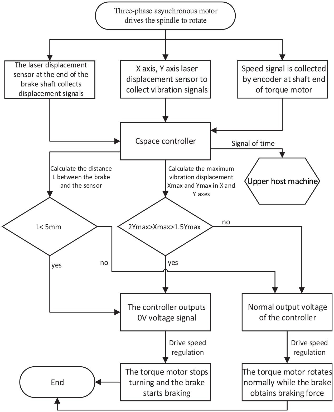
Flow chart of fault feedback braking.
The main workflow is: the vibration signal during the spindle rotation is collected by the laser displacement sensor into the Cspace controller, and the maximum vibration displacement in the radial vertical and horizontal directions of the spindle is calculated to determine whether the elliptical trajectory conditions are met, so as to send different voltage commands to the brake torque motor driver to achieve the purpose of emergency braking. To prevent the brake from braking back, a laser displacement sensor is installed at the brake pad shaft end to measure the brake lead to preventing the brake from bouncing back. At the same time, the brake lead time signal collected at the brake end is compared with the speed time signal collected by the encoder at the torque motor end to obtain a fault feedback brake performance.
Design of programming
Based on the theory of axial trajectory purification and the principle of fault feedback braking, an experimental study of the braking system is mandatory. As the Cspace controller is used for signal acquisition and control feedback, it has to be programmed first. The axial trajectory plotting and analysis is an offline analysis program, which is programmed using Labview software, the principle of which is that the Cspace controller collects data and imports it into the Labview program for analysis. The braking system fault feedback braking is an online control program, which is programmed in Matlab/Simulink. The principle is that the Cspace controller generates a control signal to achieve the fault feedback braking function by calculating the collected data through the intramural program.
Purification program design of axis locus
With the laser displacement sensor and the Cspace controller we are able to collect in real time the axial trajectory data of the rotating spindle of the electro-mechanical braking system under rotating conditions, which is transmitted to the PC for display and processing with a voltage of 0–5 V. In order to eliminate the effects of crossover signals generated by machine vibration noise during mechanical rotation, the collected signals are filtered using ensemble empirical modal decomposition (EEMD), and the signal components from the EEMD decomposition are filtered using the correlation principle and the components are checked for energy occupation to obtain a suitable data signal, and finally the reconstructed data are used to plot the axis trajectory and carry out fault Analysis.
The Labview program developed for spindle vibration axis trajectory purification includes the EEMD algorithm script, the correlation and energy share program and the axis trajectory plotting program, with the following workflow as shown in Figure 6.
(1) The information collected by the sensor is stored through the real-time data acquisition program, and then divided into X axis and Y axis data is distributed to the data writing module to generate Excel files.
(2) Organize the data of Excel files to get pure data files. Then it was imported into the Matlab script node module of Labview for joint calculation and processing to obtain IMF component and remaining items. The execution script is run in conjunction with Matlab’s EMD analysis toolbox.
(3) The raw data stream from the execution script is output as data and IMF data, where data represents the raw data and the IMF represents the eight modal components. The correlation between each IMF component and the original data is derived, and the IMF components with the highest correlation coefficients are then plotted and ranked to select the IMF components with the highest correlation coefficients. If the correlation coefficient is equal to the IMF component with the highest energy share, the verification is successful and the most relevant index is automatically brought into the axial trajectory plotting program as shown in Figure 7.
(4) After processing by the calculable correlation program, the IMF component with the largest correlation coefficient is automatically filtered and saved, and the maximum correlation coefficient IMF index is then returned to the axial trajectory plotting program as shown in Figure 8. The axial trajectory plotting program filters the input IMF components to obtain the maximum value and then integrates the X-axis and Y-axis data components to produce a XY plot reflecting the axial trajectory.

Flow chart of purification program design for axis locus.

Correlation and energy ratio program.

Axis track drawing program.
Fault feedback braking program design
As the Cspace controller is programmed to run based on matlab/simulink, the design brake fault feedback braking program is given in Figure 9. The AD module in the program represents the laser displacement sensor acquisition input port and WM_DAC16_1 represents the voltage output driver port. The main process is that once the program is imported into the controller. The initial value of the torque motor voltage can be set via the host computer to cause the motor to compress and thus the brake to generate preload. The signal collected by the spindle laser displacement sensor is converted and zeroed to achieve a zero voltage output through the adjustment of the control node, which then controls the motor power off by the driver to achieve braking. The displacement feedback module in the diagram are designed to prevent the braking response time from being too long and causing the control node signal to change resulting in braking failure, this module allows the braking to take place once and only once when the braking response is carried out. Comparison of Send_GUIdate4 from the encoder with Send_GUIdate3 from the laser displacement sensor on the brake side gives the braking response time.
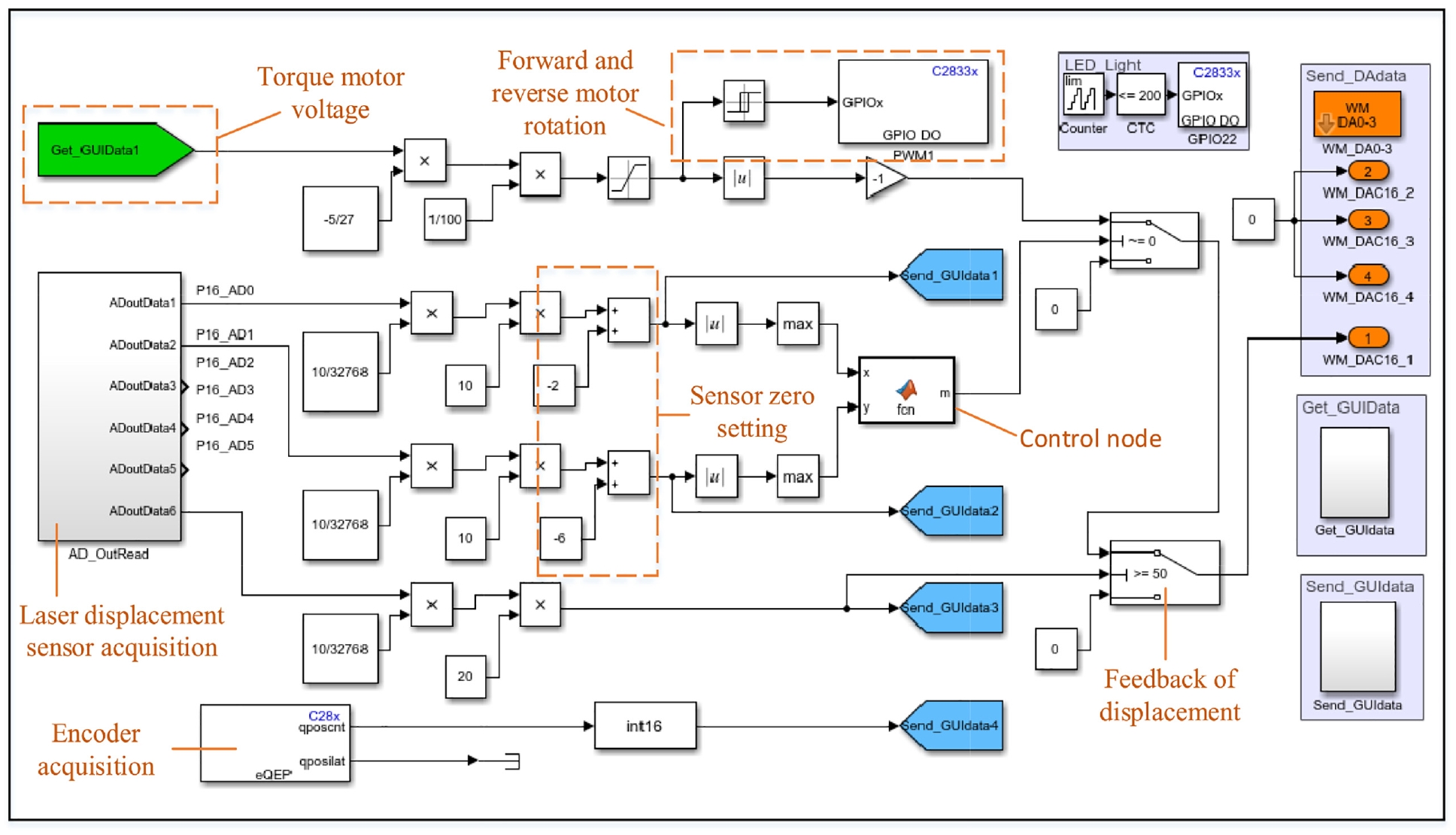
Fault feedback braking program.
Analysis of experiment
Relying on the designed program and electro-mechanical braking system test bench can develop the experimental research method as shown in Figure 10. The motor inverter controls the rotation of the system spindle motor, the electromagnetic clutch connects the motor shaft to the system spindle, the spindle laser displacement sensor collects the vibration displacement signal in the middle of the spindle, the brake end laser displacement sensor measures the braking lead, the torque motor shaft end is fitted with an optical encoder to measure the motor speed, the Cspace controller receives the signals from the sensors and processes them, the motor driver receives the voltage signal from the controller. The motor driver receives the voltage signal from the controller and controls the torque motor speed.

Experimental research methods of electro-mechanical brakes: (a) orientation map of the electro-mechanical braking system test equipment and (b) experimental flow chart for electro-mechanical braking systems.
Due to the need to obtain periodic vibration displacement data at the rotating shaft cross section during data acquisition, the laser displacement sensor at the spindle end needs to be mounted perpendicular to the spindle in an orthogonal distribution. A bracket is designed to meet the sensor mounting conditions as shown in Figure 11(a). This bracket ensures that the sensors are collected in the same cross-section and mitigates the effects of vibration on the sensor collection during the operation of the test bench. The actual laser displacement sensor mounting orientation is also shown in Figure 11(b).

Layout of laser displacement sensor: (a) sensor bracket and (b) sensor mounting position.
Axis locus purification experiment
The rotor spindle section of the electro-mechanical braking system platform provides rotational power via a three-phase asynchronous motor, with a frequency converter to control the motor speed, and an electromagnetic coupling to connect the motor shaft to the brake disc spindle. In order to artificially increase the vibration amplitude during the rotation of the spindle when carrying out the rotor unbalance test, the measure of attaching counterweights at the two rotating discs of the test platform is used. Four metal counterweights, each with a net weight of 0.402 kg, are bolted to the turntable and installed in such a way that two counterweights are installed on each turntable, with the counterweights installed in the same position between the turntables as shown in Figure 12.

Physical installation of additional counterweight block: (a) counterweight object and (b) mounting position of counterweight block.
In order to guarantee the safety of the experiment, the motor speed was set to 5 rad/s by the motor inverter, and then the laser displacement sensor was used to collect real-time data with a sampling frequency of 1000 Hz. One second of data was collected during the operation of the motor, and then the data were imported into Labview and the spectrum analysis of the Y-axis raw data was carried out as shown in Figure 13. From the spectrum waveform, it can be seen that the characteristic frequency of the original signal is 5 Hz and the amplitude spectrum is accompanied by a double frequency. According to the rotor unbalance characteristics, it can be seen that the highest frequency of the spindle vibration is the same as the motor speed, resulting in a rotor unbalanced fault during the spindle rotation.

Spectrum analysis diagram of original signal.
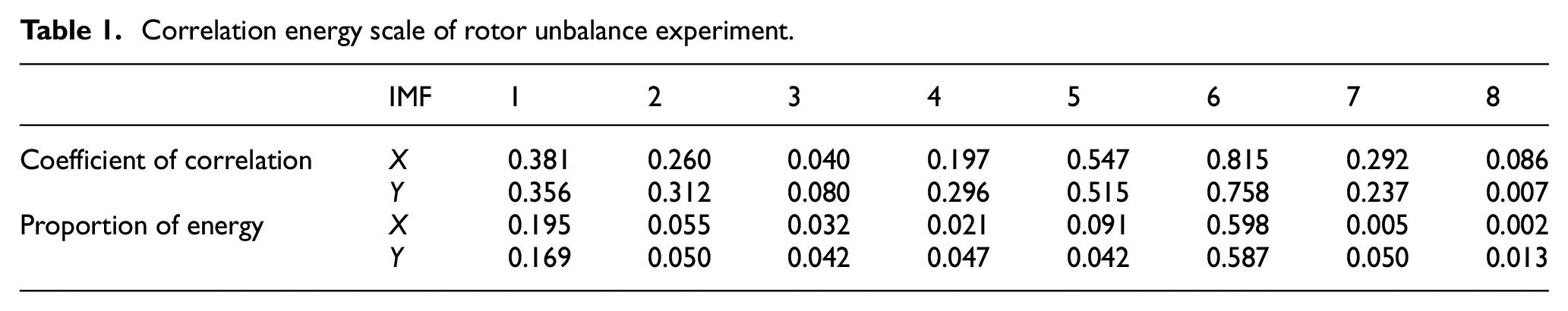
The raw vibration data collected through the EEMD decomposition program will get eight IMF reconstruction components, after the program run can get the correlation coefficient of each component and the amount of energy accounted for by the raw data, after exporting the summary as shown in Table 1. The correlation coefficients of the IMF-6 components in the X-axis and Y-axis data are the largest, indicating that they can best reflect the characteristic information of the original data; at the same time, the energy ratio of the IMF-6 components in both axes is the highest, which means that the component with the highest energy is IMF-6 after the original signal is decomposed by EEMD, indirectly confirming the correlation between the components and the original data. The correlation between the components and the original data can be represented by the correlation coefficient values as shown in Figure 14.
Correlation energy scale of rotor unbalance experiment.

Correlation coefficient and energy ratio of IMF component.
Purified IMF-6 data were exported and plotted against the original data as shown in Figure 15. The results show that the IMF-6 components obtained from the decomposition of the EEMD algorithm can filter out most of the vibration white noise signals with the automatic purification of the program, so that the X-axis and Y-axis data can retain the feature information in the original data. Subsequently, the IMF-6 components of the two axes are plotted by the axial trajectory mapping program to obtain the axial trajectory of the brake disc spindle during operation as shown in Figures 16 and 17.

Biaxial curve of experimental purification.

Axis locus of original data.

Axis locus of purified data.
Fault feedback braking experiment
With the Cspace controller, vibration displacement data can be gathered during spindle operation to create a graph of the axis trajectory. At the same time, one of the characteristics of a spindle unbalanced fault on the axis trajectory graph is that the horizontal vibration displacement is between 1.5 and 2.0 times the vertical vibration displacement. Therefore, according to this feature, the brake system can be intended to provide feedback braking experiments. A laser displacement sensor is installed at the end of the brake shaft to measure the braking lead and reaction time, and its installation orientation is shown in Figure 18(a); an optical encoder is installed at the end of the brake motor to collect the time parameters when the motor starts and stops rotating, and its installation orientation is shown in Figure 18(b).

Mounting position diagram of fault feedback brake test sensor: (a) installation orientation of displacement sensor and (b) encoder mounting azimuth.
In the preparation phase of the experiment, the two laser displacement sensors in the radial direction of the spindle were first zeroed so that their initial point displacement value was zero. The torque motor voltage is placed at 16 V so that the brake stores the braking force and disengages the brake disc in compression. The spindle is then rotated by a three-phase asynchronous motor and the motor speed is set at 1 rad/s to ensure safety, after which the displacement offset of the two sensors can be observed to be stable at 0.02 mm by the host computer. The brake end displacement sensor was adjusted to around 5.3 mm to make sure that the Cspace controller could quickly inhibit the brake from rebounding during the braking process, thus avoiding the problem of brake failure.
During the experiment, based on the principle of safety and the simplification of the experiment, a displacement disturbance away from the axis center of the spindle was given to the X-axis laser displacement sensor at some point to make the X-axis displacement offset meet the unbalanced fault characteristics, and the displacement offset diagram as shown in Figure 19 was obtained. It can be seen from the figure that the unbalanced fault disturbance node time T1 = 0.663 s, displacement offset F = 0.032 mm, meet the braking conditions of the feedback program.
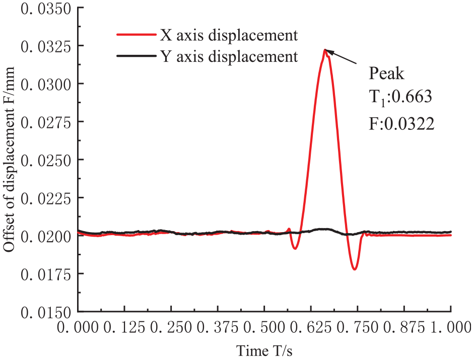
Radial vibration displacement offset of the spindle.
The brake torque motor then receives a power-off command and the brake starts to release its internal compression force to make the motor rotate and press the brake pad against the brake disc to complete the braking. At this point, the data collected by the encoder and displacement sensor installed at the end of the brake shaft can be obtained as shown in Figures 20 and 21, from Figure 20 it can be seen that the encoder at the motor end collects the motor rotation time as T21 = 0.766 s and the cut-off time as T22 = 1.893 s; from Figure 21 it can be seen that the displacement sensor at the brake pad end collects the brake lead start time as T31 = 0.776 s and the cut-off time as T32 = 1.941 s.

Angular displacement of brake motor.

Brake guide diagram.
The results show that the time taken by the brake system from the fault signal to the brake voltage output is about 0.103 s, which are within the normal response time. At the same time, brake motor rotation time to the release of compression force is 0.01 s, the braking time is 1.175 s, within a reasonable braking time. The experiment verifies that the designed fault feedback braking control program can effectively complete the emergency braking behavior required when a spindle imbalance fault occurs in the electro-mechanical braking system, providing a reasonable reference for the electro-mechanical braking system fault feedback research.
Conclusion
In this paper, the brake disc spindle of an electro-mechanical braking system is used as the research object and a braking system experimental bench is built relying on similar scaling theory. In order to analyze the unbalanced fault information during the operation of the brake disc spindle, an offline purification procedure for the axial trajectory and an online control procedure for the fault feedback braking are designed and the following conclusions are drawn from the experimental study:
(1) Based on the axis trajectory purification procedure written by the ensemble empirical modal decomposition algorithm, a rotor unbalanced fault experiment was developed by choosing the method of attaching a counterweight block to one side of the rotor. The results show that the filtered reconstructed X-axis and Y-axis IMF components. After correlation and energy analysis, have a correlation coefficient of about 0.8 for the IMF-6 component and an energy coefficient of 0.5 or more, which can be considered as valid components. The program then automatically reconstructed the IMF-6 components of both axes to plot the experimental axis trajectory. According to the image comparison, it can be observed that the spindle unbalance axis trajectory is a standard ellipse, and this purification method effectively extracts and shows the unbalanced fault of the brake disc spindle of the electro-mechanical brake system.
(2) Based on the theory that the X-axis vibration offset is 1.5–2.0 times that of the Y-axis in the unbalanced fault characteristics of the axis trajectory, a simulink braking control feedback program was designed. The braking experiment shows that the response time of the Cspace controller from collecting the signal to giving the command is 0.103 s, the response time of the torque motor of the brake from receiving the power-off signal to starting to rotate is 0.01 s, and the time used for the brake internal disc spring to drive the brake tile to press the brake disc to complete the braking is 1.175 s. Therefore, the time used for unbalanced fault fault feedback braking control is 1.278 s, indicating that this braking control feedback method can effectively fulfill the need for emergency braking in the event of an electro-mechanical braking system fault.
(3) The research methods used for the analysis of unbalanced fault during spindle rotation are somewhat limited. During the data processing, the signals collected online need to be initially processed before they can be imported into the Labview program for analysis, which results in the entire process being analyzed offline. How to smoothly transform the subsequent analysis process into an online analysis state is a direction for future research. At the same time, feedback control, how to effectively reduce the reaction time required in the control process, for the reasonable implementation of emergency braking is of great significance.
Footnotes
Appendix
Acknowledgements
The authors thank the anonymous reviewers for their critical and constructive review of the manuscript.
Handling Editor: Chenhui Liang
Declaration of conflicting interests
The author(s) declared no potential conflicts of interest with respect to the research, authorship, and/or publication of this article.
Funding
The author(s) disclosed receipt of the following financial support for the research, authorship, and/or publication of this article: This work is supported by the National Natural Science Foundation of China (No. 51904009), and the Open Fund of Anhui Key Laboratory of Mine Intelligent Equipment and Technology (No. ZKSYS202102).