
Abstract
For cutting a large screw, the cutting force and temperature have direct impact on machined surface quality, such as accumulated pitch error in geometric error. Excited by cutting force, the axial deflections directly affecting accumulated pitch error were studied based on the beam theory. By experiments, the axial cutting force was predicted with a 96% confident interval, and the tool number and cutting depth were found to be significant terms. Tested under increasing cutting speeds, the temperature rise of workpiece and accumulated pitch error both decreased obviously. Thus the higher cutting speed could improve the cutting precision of a full-length large screw.
Introduction
For a large screw, the whirlwind milling (WM) has been widely applied. 1 Due to the specific characteristic, the geometric error, especially for the accumulated pitch error, was inevitably and even unfavorable under some unreasonable process parameters. The cutting force and temperature have direct effect on the accumulated pitch error of screw. Significant efforts were made to investigate the cutting force and temperature in turning2,3 and milling.4,5 Remarkable difference actuated the study to investigate cutting force and temperature in WM.
Considering of the vital importance of the cutting force on the surface quality, 6 the state and variance law of the cutting force were widely studied. Grossi 7 modeled efficiently the specific cutting force coefficients identified by forces signals, and proved its effectiveness for the chatter prediction. Liu et al. 8 proposed a theoretical model based on energy theory. The predicted cutting forces were verified by turning experiments. Wang et al. 9 established a mechanistic cutting force model based on ductile and brittle fracture material removal modes. Altintas et al. 10 analyzed the stability lobes for milling cutters. The stability was formulated and then demonstrated by experiments. Considering the entry and exit angles, Jing et al. 11 modeled the cutting force as the function of coefficients calculated by uncut chip thickness. By theories and experiments, Luan et al. 12 developed an infinitesimal cutting force model for predicting the power consumption. While for WM, Song and Zuo 13 proposed equivalent cutting volume to simulate the cutting force and verified its effectiveness. Ni and Li 14 modeled a undeformed chip thickness and then studied the cutting force by DEFORM software.
For WM, the technology has been applied in precision machining. But due to technical confidentiality and other reasons, there are few papers reported on the basic theory and cutting mechanism, and most of them are on the principle and surface contour forming of WM. Lee et al. 15 modeled the tool-nose trajectory by the internal and the external WM method, and predicted the over-cut amount of the screw surface. Mohan and Zuo 16 modeled the tool’s working trajectory in WM, and analyzed the effect of the tool profile on the cutting process. Merticaru et al. 17 developed a secondary model to simulate the screw’s profile error. Zanger et al. 18 modeled the surface profile of a screw in dry WM. Ahn et al. 19 studied the effects of various errors, such as run-out errors of a tool axis, tool setup errors, and workpiece deflection. Guo et al. 20 utilized response surface methodology to obtain the multi-optimization of surface roughness and cutting force. Wang et al. 21 modeled an analytical approach to investigate WM’s circularity error, scallop height, and surface roughness. Han and Liu 22 analyzed the theoretical machining error by dividing the scallop height into axial and cross-sectional errors. Merticaru et al. 23 optimized the WM machining parameters to obtain a high accuracy. Wang et al. 24 investigated the dynamic responses caused by discontinuous cutting forces in WM, and optimized the surface quality.
Most studies of the cutting force and temperature focused on traditional cutting method, while for whirlwind milling, the state of the cutting force and temperature is uncommonly reported. Additionally, the geometric error should be studied to improve the machining precision. Thus, the present aim is to study the intrinsic relationship among the cutting force, temperature, and geometric error, which is benefit to improve the machining precision of WM.
Materials and methods
In cutting tests, the Figure 1(a) demonstrates a WM machine developed by Hanjiang Machine Tool Co., Ltd, China. The tools rotate with a high rotating speed, and the screw with a low one. 25 The instantaneous cutting depth and widths are changing. For cutting force testing, the system was independently developed by the team. 26 All tools have Seco CCGW09T304S-01020-LF CBN inserts, and the CBN content is 50%, rake angle −8°, and chamfer parameters of 0.15 mm × 25°. The material of screw is GCr15 bearing steel. In Figure 1(b), a 3D piezoelectric force sensor was fastened and installed between the tool apron and tool bar by the thread. The sensitivity of sensor is 5 mV/N in axial direction, and the testing range −1 to 1 kN. Then the force signal was transferred through a multi-channel slip ring. The system P8020 was used for data acquisition. Its sampling frequency is 5000 Hz, which is far greater than the cutting force frequency (<100 Hz). A stable cutting time was selected to acquire the force signal.
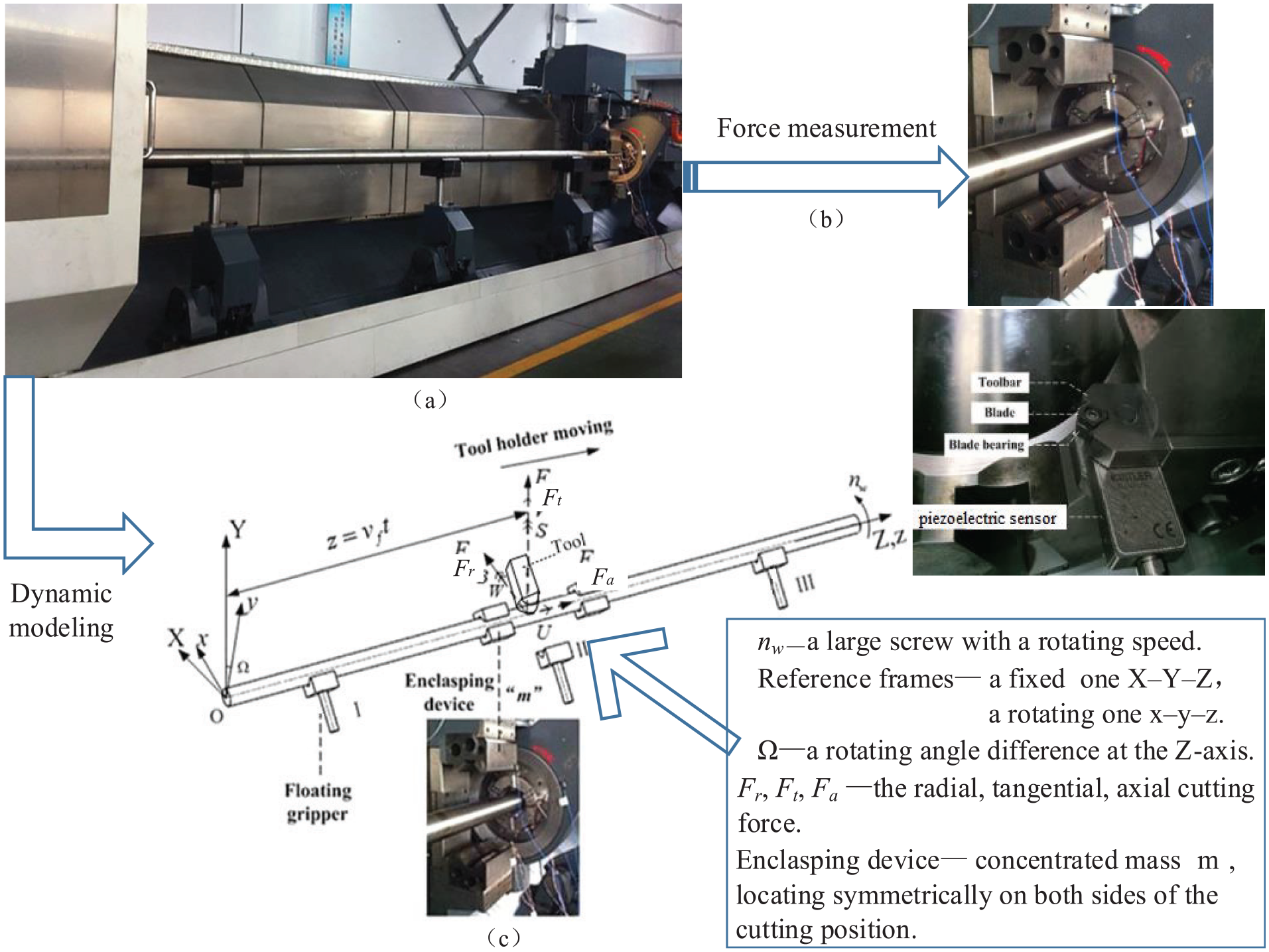
The WM’s (a) machine, (b) force measurement, and (c) dynamic modeling description.
As it known, the geometric error is decided by cutting force between the tool and workpiece during the cutting. Thus, the cutting force and vibration must be studied for improving the machining precision. Among the geometric errors, the total axial deflection is the most important parameter for effecting the geometric precision. In whirlwind milling, the influence of screw’s surface raceway on the workpiece section was ignored, and assumed that its cross section was circular. The screw are configured with a clamped–hinged boundary, while other parts are supported by enclasping devices and floating grippers. In Figure 1(c), the two frames are utilized to describe the system motion. Due to the insignificant effect of floating gripper on axial deflection, the floating gripper was ignored in modeling the vibration. Although three components of cutting force mentioned in Figure 1, the most important component for effecting the axial deflection is the axial force, and thus discussed in the study.
Prediction of geometric error
Considering that the instantaneous cutting depths and widths are changing in whirlwind milling, thus the maximum instantaneous cutting depth was chosen as the cutting depth in Table 1. The “tool number” represented the number of tools installed on the tool’s holder, which is similar to the teeth of cutter. In Table 1, the value of axial force was taking the arithmetic mean value of the maximum axial force of the ten adjacent cutting periods. Take the tested values under a certain working condition as an example, the axial cutting forces were collected in 10 adjacent cutting periods as 53.74, 52.26, 55.62, 51.16, 52.32, 53.11, 48.62, 50.08, 51.83, 53.56 N, respectively. Its average is 52.23 N, and the maximum uncertainty within acceptable error range. Thus the average value can be effective in following study.
Experiment design and results.
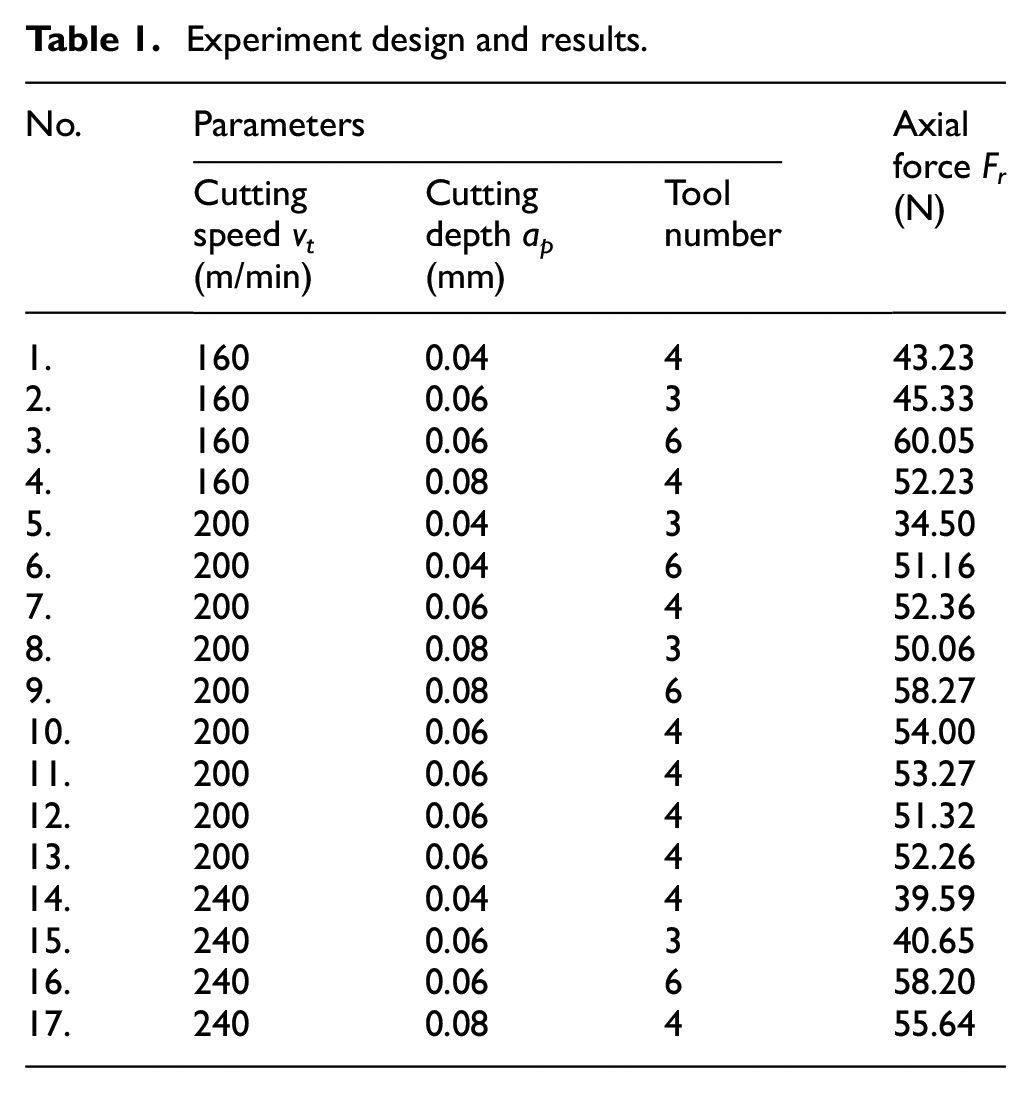
Three levels in independent cutting speed, cutting depth and tool number were selected as (160, 200, 240) m/min, (0.04, 0.06, 0.08) mm, and (3, 4, 6). According to the Box-Behnken design, some experiments should be conducted, and the axial cutting forces were tested in Table 1.
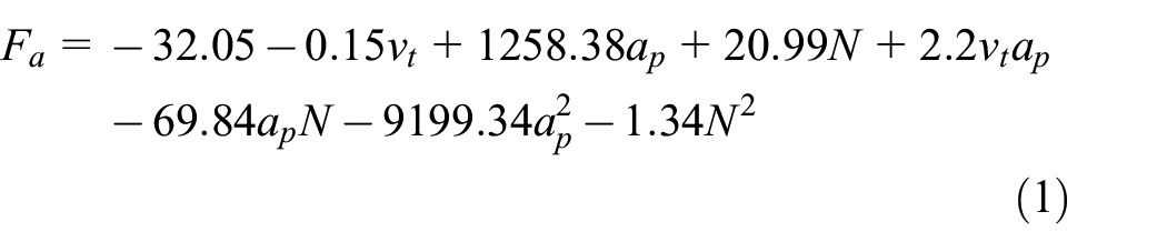
The statistical significance of fitted quadratic cutting force model was evaluated as Figure 2(a). The model allowed the predicting cutting force with a 96% confident interval. By the least squares regression and the elimination process, the quadratic model of actual axial cutting force could be presented in equation (1). While other factors were kept constant, the single and interaction influences on Fa were presented in Figure 2(a). It is clearly observed that tool number strongly affects axial cutting force, and ap2 has an increasing effect.

The flow figure of modeling the geometric error: (a) analysis of variance, (b) potential energy Us, (c) kinetic energy Ts, (d) motion equations, and (e) constraints.
In any cross section of the screw, the instantaneous axial displacement U is expressed as the functions of location z and cutting time t.

If assumed shape functions are selected, where n is the total number of assumed modes; ui, vi, wi, pi, and qi are the time-dependent generalized coordinates; ϕ and φ are the assumed shape functions. If the full length of the screw is L, then the assumed shape functions are selected as follows.

For simplicity, a uniform screw with a circular cross section is assumed in the present study. The potential energy Us which includes pure bending, shear deformation, and axial deformation, is presented in Figure 2(b). Similarly, the screw kinetic energy Ts is expressed in Figure 2(c).
By the Lagrangian approach, the motion equations can be obtained and simplified in Figure 2(d). If matrices

During the whirlwind milling, the left end of the workpiece is fixed by a chuck and driven to rotate at a lower angular speed, and the right one is supported by a tailstock, thus simplifying the workpiece as a beam in a clamped-hinged way. As the left (clamped) and right (hinged) ends of the screw were represented by zl and zr, the displacements should meet the following requirements by combining the constraints in Figure 2(e). The transform equation in a generalized coordinate can be reduced by substituting constraints T into the dynamics of the system, as follows. Thus, the deflection U caused by the WM cutting forces can be calculated.

Caused by machining, the axial deflection has a direct impact on the workpiece‘s pitch error. In solving the established formula (5), the representative Runge-Kutta variable step method was adopted to achieve high iteration efficiency. Combined with the parameters in Table 1, the more accurate simulation results would be obtained. Then the axial deflections of different machining positions under different cutting parameters were simulated (Table 2).
Parameters in simulation.

Under different cutting conditions and positions in Figure 3, the maximum positive axial deflection occurs at the cutting position of 1.3 m, and the maximum negative one occurs at the position of 2.44 m. In Figure 3(a), with the increase of cutting speed, the maximum axial positive and negative deflections were both increasing. As the feed speed increased, the maximum radial deflection showed the same trend, and the positive one under the feed speed vf = 0.08 m/min is the largest, as shown in Figure 3(b). In addition, when the cutting depth is increased, the maximum axial deflection first increased and then decreased, and arrived the peak under cutting depth ap = 0.12 mm (Figure 3(c)). During the full-length machining of large screws, the sum of all axial deflections, that is, the axial elongation, has a significant impact on the lead screw pitch error.

The axial deflections by changing (a) cutting speed v t , (b) feeding speed v f , and (c) cutting depth a p .
Experiments
Experiments of cutting temperature
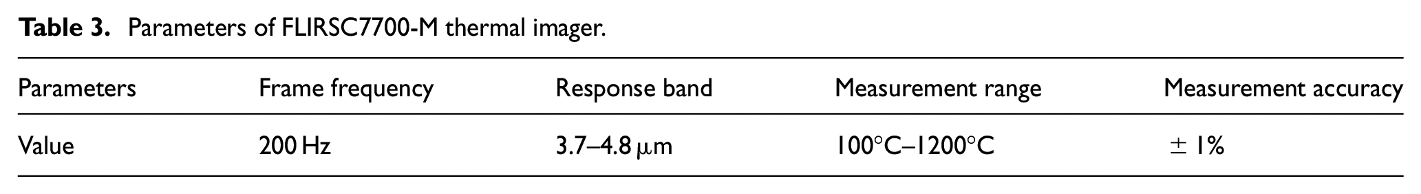
The cutting temperature experiments were auxiliary to study the cutting status. Although that the cutting temperature is not considered in modeling the axial deflection, the temperature rise of workpiece also has a great influence on the cumulative pitch error. The FLIR SC7700-M high-speed cooling infrared thermal imager was used for the non-contact and high-resolution temperature imaging. The relevant characteristic parameters were show in Table 3.
Parameters of FLIRSC7700-M thermal imager.
During processing, due to the continuous rotation of the screw and tools, the cutting area also rotates, and part of the area would be blocked by the machine tool and the screw itself, which made the probe cannot detect. Therefore, according to the on-site working conditions, the thermal imager was fixed on the platform, and was adjusted around 1 m away from the cutting tool, which ensure that the concerned cutting area is at the center of the infrared thermal-imager imaging. Focusing is necessary before every temperature acquisition to ensure the measurement accuracy.
If the frame rate was set as 200 Hz, the time interval of recording data was 0.005 s. Under cutting speed 200 min, cutting depth 0.06 mm and feeding speed 0.0452 m/min, the temperature changes periodically with time shown in Figure 4. The average of the highest temperature in 10 cutting periods was taken as the maximum temperature under current cutting parameter.

The periodical temperature changes by test.
Experiments of maximum temperature and geometric error
For detecting the law among the cutting force, maximum temperature, and geometric error, the tests changing the cutting speed were chosen. Thus fixing tool number 4 and cutting depth 0.06 mm, the cutting speed 160, 180, 200, and 240 m/min were selected. The maximum temperature of processing area in stable cutting stage was obtained by using the infrared thermal imager as the maximum temperature value in WM under this group of process parameters.
Seen from Table 4, as cutting speed increases, the maximum temperature in processing area is firstly increased to that of cutting speed 180 m/min, and then decreased, which were shown in Figure 5(a)–5(d). While for the temperature rise of screw, it decreased obviously with increasing cutting speed. It may due to that the residence time of cutting tool on the screw decreased as improving cutting speed, then the cutting heat has fewer time transferred to the screw. Similarly, the accumulated pitch error is significantly reduced. The reason for the phenomenon is due to the decreased axial cutting force. Similarly in Table 4, as the temperature rise of workpiece decreased, the expansion due to the temperature and heat also decreased, which could make a smaller cumulative pitch error. Thus for whirlwind milling, the increment of cutting speed could effectively reduce the temperature rise and accumulated pitch error, which is the most beneficial to improve cutting precision of a full-length large screw.
Tested data under different cutting speeds.


The maximum temperature value under different cutting speeds: (a) 160 m/min, (b) 180 m/min, (c) 200 m/min, and (d) 240 m/min.
Conclusions
For analyzing the cumulative pitch error of a large screw, the axial cutting force was firstly modeled by experiments. Then the axial deflections were studied under different cutting parameters. Lastly the maximum temperatures in processing area were experiments under different cutting speeds, and the intrinsic relationship among the cutting force, temperature, and geometric error were revealed. Main results were included as followed:
Excited by cutting force, the axial deflection was studied under established cutting vibration model. The variation was further analyzed under different cutting parameters. The results can be beneficial to reduce the pitch error of large-scale screw processing, and can extend in whirlwind milling a more longer screw.
By experiments, the axial cutting force was established allowing the predicting cutting force with a 96% confident interval. From the regression analysis, the tool number and cutting depth (ap2) were found to be significant terms on axial cutting force. The cutting force model was verified to be effective for predicting and analyzing the geometrical error.
In experiments with increasing cutting speeds, the maximum temperature in processing area is firstly increased to the cutting condition of cutting speed 180 m/min, and then decreased. Then the temperature rise of screw decreased obviously. Similarly, the accumulated pitch error was also significantly reduced. Thus for whirlwind milling, the high cutting speed could reduce the temperature rise and accumulated pitch error effectively, which is the most beneficial to improve cutting precision of a full-length large screw.
Footnotes
Handling Editor: Chenhui Liang
Declaration of conflicting interests
The author(s) declared no potential conflicts of interest with respect to the research, authorship, and/or publication of this article.
Funding
The author(s) disclosed receipt of the following financial support for the research, authorship, and/or publication of this article: This work was supported by the National Natural Science Foundation of China (grant number 51805243, 2018).