
Abstract
The focus of this work is to investigate the ticking noise produced by the vibro-impacts between piston pin and connecting rod small head bearing. Numerical calculation and experimental verification methods were adopted and a novel method to control this intermittent noise was proposed. The dynamic model of crankshaft connecting rod piston with full floating piston pin was established and the essence of piston pin ticking was analyzed. The occurrence time of the ticking corresponded to the crankshaft angle when the resultant force of piston pin passed through the 0 axis. At the moment of impact, the peak hydraulic pressure of lubricating oil was found to be proportional to the impact strength. In order to suppress this noise, the oil groove on the bearing was designed considering the minimum oil film. After adding the oil groove, the impact intensity was significantly reduced and the noise was even eliminated. The calculated results were in good agreement with the experimental tests, and the research of this work provided a reference for controlling the ticking noise of piston pin.
Keywords
Introduction
The sound of engine is a significant subjective method for customers to evaluate the quality of passenger cars. A car with pure sound usually represent high quality.1,2 Due to the persistent roar of the engine and the continuous noise of the power train, some intermittent noises of engine were masked, such as rattle, ticking and croaking. In recent years, an enormous amount of research has been done on the mechanism and control methods of various noises on engine, as combustion noise, 3 piston slap noise, 4 belt noise, 5 and so on. Especially the application of active control system, such as suspension active control system, 6 seat active control system, 7 noise active control system. 8 These studies had greatly weakened the noise level in the vehicle and improved driving comfort. Therefore, masking this intermittent noise was unrealistic. The piston pin ticking noise of the engine is a kind of intermittent impact noise, which increases the vibration, reduces the fatigue life of parts and reduces the comfort of vehicle driving. This phenomenon occurs under low speed and light load, qualitatively similar to the noise produced from a running clock. 9
The experimental results of Werkmann et al. 10 found that the level of ticking noise was influenced by the value of clearance between piston pin and connecting rod small head bearing, therefore, it can be controlled by reducing the clearance. However, the research of Ding et al. 11 showed that the clearance was too small, which may result in seizure and friction wear of the bearing. Reducing the clearance to control this noise was restricted by friction wear. The essence of this noise must be analyzed, so as to find an appropriate control method. Moshrefi et al. 12 proposed an experimental method to quantitatively evaluate the ticking of piston pin in order to verify the design scheme. Ticking was primarily caused by the impact between the piston pin and the connecting rod small head bearing. It occurred at the reverse moment of the movement of the piston pin relative to the connecting rod small head bearing. 13 With these experimental researches, some factors affecting the ticking of piston pin were obtained, such as the clearance value between piston pin and small head, nevertheless, without clear theoretical analysis.
The ticking noise of piston pin belongs to the problem caused by multi-body dynamic contact and collision with lubricated clearance. Over the years, various studies on the lubricating joint with clearance in the multi-body mechanical systems had been conducted. Rave and Schwab are the pioneers who took account of the lubrication actions at the multi-body systems. 14 Under the assumption of infinitely short and infinitely long radial bearings, Flores et al. 15 established the dynamic model of multi-body system considering lubrication and clearance by embedding the Reynolds equation into the rigid multi-body dynamic system. Tian et al. proposed a general and comprehensive model by integrating the elastic hydrodynamic lubrication (EHD) model into the dynamic system of flexible multi-body system.16,17 Zhao et al. successfully applied the multi-body dynamics model and lubrication rotating joint to the dynamics and friction calculation and analysis of connecting rod small head bearing.18,19 For half-floating piston pin, the simulation result of Zuo et al. 20 showed that the piston pin ticking occurred at the time when the direction of the force of the piston pin reversed. A bigger piston pin bearing clearance or a higher engine speed can result in a greater piston pin ticking noise. The research of Lu et al. 21 showed that the vibration acceleration of system with multi clearances was much larger than that of single gap system. Li et al. 22 found that the undesired transient impact by clearance joints on the mechanical system can be sup-pressed by flexible sleeves, but it is not easy to achieve by the high temperature in the piston cylinder.
According to the authors’ knowledge, most of these studies shown above are associated with the dynamic performance of the multi-body system and the friction and wear performance of the bearing. Little work has been carried out on the ticking noise of the full floating piston pin for automobile engine due to the shielding effect of other high-level noise. Now, with the reduction of other high-level noise, the piston pin noise must be controlled to further improve driving comfort.
Therefore, the objective of this work was to study the essence and control method of piston pin ticking noise. In the case of ignoring the impact of the piston on the cylinder liner, a multi-body dynamic model was established, and the simulation calculation was carried out. Then, the essence of ticking was analyzed and a novel method was proposed to control the ticking noise. In addition, the proposed control method was verified by experiments. The result showed that adding oil groove on the bearing was an effectively method to control the piston pin ticking noise.
In the subsequent discussion the term connecting rod small head bearing is called bearing for short.
Analysis model
Structure introduction and parameter selection
The engine structure has been strengthened gradually. For modern engines, the fully floating piston pin joint with better friction uniformity function is a typical configuration. The structure of fully floating piston pin is shown in Figure 1. Piston pin can rotate and move radially in the piston pin seats and connecting rod small head bearing.

Full-floating piston pin model.
Piston pin ticking noise was audible in a four-cylinder supercharged gasoline engine. The subjective performance of this noise was obvious at low speed and light load. However, it cannot be identified at heavy load. This engine was taken as the object for investigation and research, and the basic engine parameters are shown in Table 1.
Basic parameters of supercharged engine.

Motion equation of the multibody system
The crankshaft connecting rod piston motion relationship is shown in Figure 2. O-XYZ is the global coordinate system fixed on the crankshaft axis, where Oi (i = 1, 2, 3, and 4) are the center of mass of crankshaft arm, connecting nod, piston pin and piston, respectively. ω is the rotational angular speed of the crank. L1 and L2 are the length of crankshaft arm and connecting rod, respectively. L3 is distance between center of mass of piston pin and piston. γi (i = 1, 2, and 3) are the included angle between crank arm and Z axis, connecting rod and crank arm and connecting rod and Z axis, respectively.

Schematic of Crankshaft connecting rod piston motion.
The local coordinate system O1-X1Y1Z1, O2-X2Y2Z2, O3-X3Y3Z3, and O4-X4Y4Z4 are fixed in the center of mass of crankshaft, connecting rod, piston pin and piston, respectively. All the local coordinate systems are also parallel to the global one.
The relationship between the local coordinates and the system coordinates can be expressed as


where φi (i = 1, 2, 3, and 4) are the included angle between the connecting line from the origin of the system coordinate to the center of mass of each component and the Z axis, respectively.
Applying Newton-Euler method, dynamic equation of crankshaft-connecting rod-piston can be written as

here i = 1, 2, 3, and 4 are the numbers of crank, connecting rod, piston pin and piston respectively. ri (xi, yi, zi) T , Ii = diag(Iix, Iiy, Iiz), and Fi (Fix, 0, Fiz) T are the center of mass coordinate, moment of inertia matrix and external force applied to the center of mass, respectively. g = (0, 0, g) is the gravitational acceleration.
The movement of the piston is constrained by the cylinder. Then, the displacement, velocity and acceleration of the center of mass of the piston pin in the Z direction can be calculated from the equations (1) to (5). However, if there are clearances between piston pin with piston pin boss and bearing, the multi-body dynamic equation (5) becomes

where f is the impact force caused by the clearances, which can be calculated by hydrodynamic pressure and rough peak contact force. It was analyzed carefully as follows.
The hydrodynamic lubrication model of bearing
The bearing is a dynamic load bearing, and the oil film bearing capacity comes from wedge effect and squeeze oil film effect. In this study, the oil film pressure was evaluated according to the average Reynolds equation proposed by Patir and Cheng, 23 and the corresponding Reynolds equation is written as

where x and y refer to the circumferential and axial direction of the unfolded bearing. h is the oil film thickness. μ is the dynamic viscosity. ϕx and ϕy are pressure flow factor in directions X and Y, respectively. ϕs is the shear flow factor. U1 and U2 are linear speed of piston pin and bearing, respectively. hT is the oil film thickness considering roughness. σ is the root mean square value of the surface roughness of piston pin and bearing.
The balance relationship of load and pressure of piston pin is shown in Figure 3. The position of piston pin axis OP is depended on the balance relationship between pin load PL, rotating pressure lubrication bearing capacity PT, extrusion lubrication bearing capacity PR and rough peak contact bearing capacity PC.

Schematic of the balance between piston pin load and oil film bearing capacity.
In Figures 3, α is the included angle between the connecting line between the center of piston pin and the center of shaft sleeve and axis Z. β is the included angle between PL and axis Z. θ is the included angle between PT and PR. θ3 is a counterclockwise angle starting from the connecting line between the piston pin and the small end of the connecting rod. h is the oil film thickness.

Where Pa is the cylinder pressure, Pq is centrifugal force of piston and piston pin, γ3 is angle between connecting rod and Z-axis.
The oil film thickness h is written as

where δ is the clearance value between piston pin and bearing, ε is eccentricity.
The solution of equation (7) requires the piston pin motion state obtained from equation (6). However, the solution of equation (6) requires the hydraulic pressure value of equation (7). It needs to be solved through cyclic iteration, which has been analyzed in part 3.
Boundary conditions for equation (7) are given as below

where B is the width of the bearing, θ1 is the starting angle of oil film, θ2 is the end angle of oil film
Rough peak contact force
When the lubrication changes from the fluid lubrication to the boundary lubrication, the load of the piston pin is shared by the asperity contact of the rough peak and the fluid film pressure. The load carrying share from the asperity contact was evaluated according to the Greenwood and Tripp model. 24


where σ1 and σ2 are the roughness of the inner surface of the piston pin and bearing respectively. ηs is the surface density of asperity peak. β is the peak curvature radius. E denotes the composite elastic modulus. ν1 and ν2 are the Poisson’s ratio of piston pin and bearing, respectively.
Simulation calculation and result analysis
Simulation calculation
Base on the dynamic model presented above, numerical analysis was performed to evaluate the piston pin ticking noise. The parameters of the contact pair between the piston pin and bearing are shown in Table 2.
Basic parameters of contact pair.

The components were meshed by software HyperMesh (2016), and the commercial finite element program Abaqus (2019) were employed to perform the computations. The single cylinder model of crankshaft connecting rod piston was established, and the mesh model of connecting rod is shown in Figure 4. The C3D10M element was adopted for connecting rod body. M3D4r membrane element was adopted for small end bearing, with 3 layers, 24 nodes in axial direction, and 60 nodes in circumferential direction. M3D4r membrane elements were used as the difference grid for EHD calculation of oil film lubrication.

The mesh model of the connecting rod.
In this work, the central difference method and successive over relaxation method (SOR) were used to calculate equation (7). An equidistant grid was adopted. The medium difference formula was applied, and the partial differential equation of the center point Pi,j can be written as 25
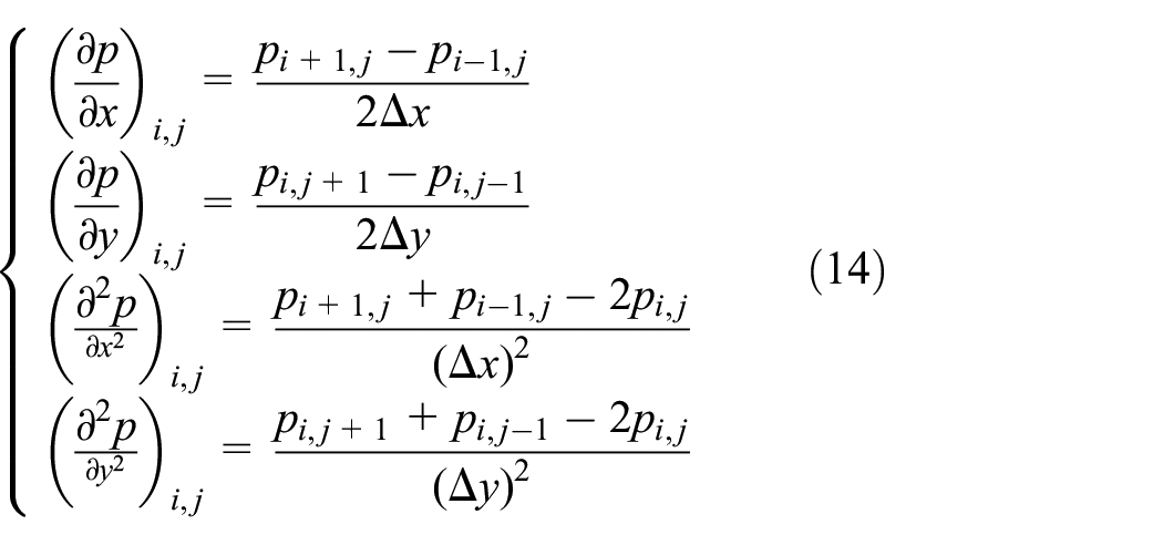
Then, equation (7) becomes

where A, B, C, D, and F can be determined by equation (7). From equations (14) and (15), the relationship between the pressure of each node and the pressure of adjacent nodes can be written as

here, CN, CS, CE, CW, G can be determined by equations (14) and (15), and the detail can be found in reference. 25 Successive over relaxation iterative was used, equation (16) becomes
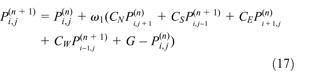
here, Pi,j(n + 1) are the n + 1 iteration results, Pi,j(n) are the n iteration results, ω1 is the relaxation coefficient.
Combining equations (10), the hydrodynamic pressure at each point of the oil film in the bearing can be calculated conveniently by computer.
As mentioned above, the solution depends on iteration, and the whole computational procedure was summarized and depicted in the flowchart of Figure 5. The iterative step of crankshaft angle was 0.00125°. The iterative calculation was stopped if the position error at the end of last two cycles was less than 0.1%.

Flowchart of computational procedure for the lubrication and dynamics analysis.
Though the iterative calculation, the dependence of piston pin displacement, velocity, acceleration, oil film hydrodynamic pressure and asperity contact pressure on crankshaft angle were obtained.
Analysis of calculation results with 15 N.m load
In this section, the dynamic response of piston pin was simulated on the conditions that the engine speed was 1000 rpm, oil temperature was 90°C, the clearance between piston pin with bearing was 20 μm and the output torque was 15 N.m.
Figure 6(a) and (b) show the relative velocity of the piston pin in the Z direction obtained from the experiment result in reference 13 and the numerical calculation in this paper, respectively. Zero degree position of the Figure 6(b) (exhaust top dead center) corresponds to 360° of Figure 6(a). From the Figure 6, it is obvious that there were two steps of the relative velocity of the piston pin in the Z direction, and the corresponding gas pressures value were equivalent at the time of steps of the relative velocity. The crank angle times of the relative velocity steps of the two engines were different, which was mainly caused by the different combustion pressure curves of the two engines. Therefore, the simulation model is credible.

Relative velocity of piston pin and bearing and bearing versus crank angle: (a) results in references and (b) results in this paper.
In a working cycle, the twice relative velocity peaks of the piston pin are −0.103m/s and 0.048 m/s, respectively. The experimental results showed that ticking noise was not found in case the relative velocity of piston pin was 0.04 m/s and the noise was audible at 0.12 m/s. 13
Figure 7(a) presents the velocity of the piston pin moving in the Z direction relative to the bearing.

Dynamic responses of piston pin: (a) relative velocity of piston pin and bearing versus crank angle, (b) acceleration of piston pin versus crank angle, and (c) relative displacement of piston pin and bearing versus crank angle.
Figure 7(b) presents the acceleration of the piston pin moving in the Z direction. It can be seen that the step change value of acceleration is sharply at the moment of impact. The first one is at the crank angle range of 45°–56° in the intake stroke, and the second one is at the crank angle range of 694°–702° in the exhaust stroke. The higher level of piston pin impact causes a larger range of step change in the acceleration of piston pin on Z-axis. This also contributes to a greater radiation noise. 20 The step change value in the acceleration of piston pin on Z-axis was used to evaluate the impact strength of the piston pin.
Figure 7(c) presents the displacement of piston pin moving in Z direction relative to the bearing. Combining Figure 7(b), it can be found that the piston pin moves downward from the top to the bottom of the bearing at the first step change of acceleration, and it moves to the opposite direction at the second step change of acceleration.
At the moment of impact, the minimum oil film thickness between the piston pin and the bearing is 4.8μm, significantly greater than the bearing roughness value Ra0.58, indicating that the piston pin does not collide directly with the bearing.
Figure 9 presents the oil peak pressure without oil groove on the small head of the connecting rod. Figures 8 and 9 show that the film thickness decreases sharply while the piston pin moves toward to the bearing, and the pressure of the film increase significantly. Then, the vibration is generated by this pressure and the ticking noise is radiated.
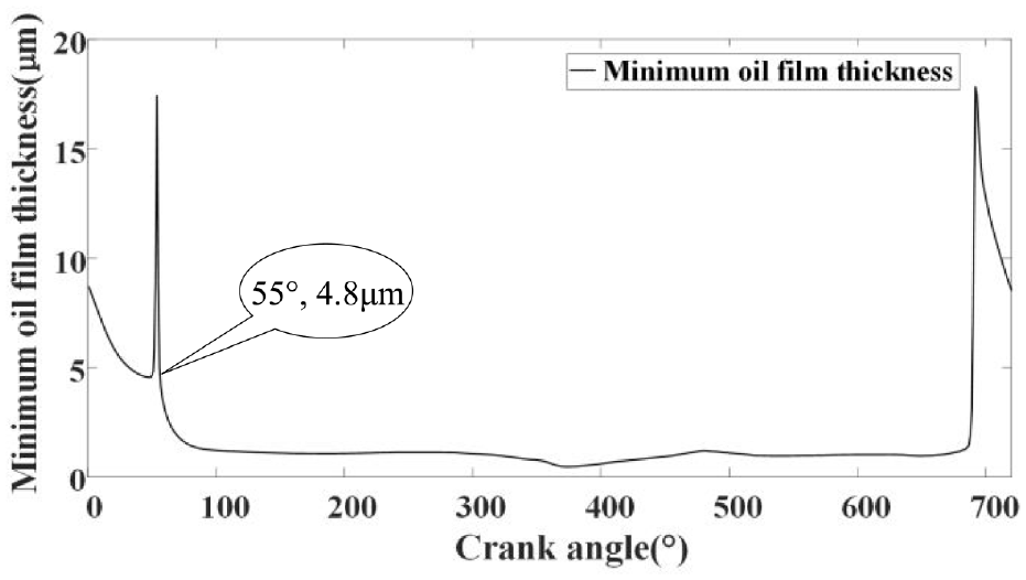
Dependence of minimum oil film thickness on crank angle.
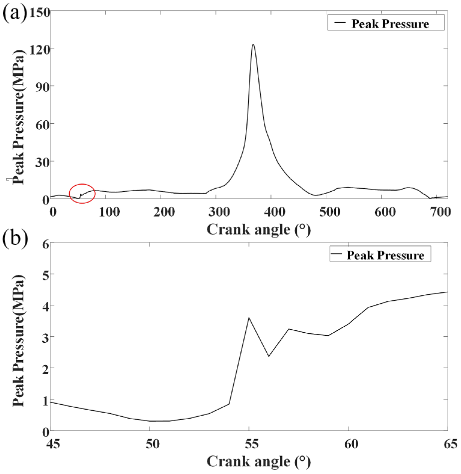
Dependence of peak pressure on crank angle: (a) a whole work cycle and (b) local zoom.
The force of the piston pin in a cycle is shown in Figure 10. The gas force and the centrifugal force are the force on the piston pin caused by the pressure in the cylinder and centrifugal force of piston and piston pin respectively, the two forces are combined into the resultant force. The positive direction of each force is the same as the positive direction of the Z axis.
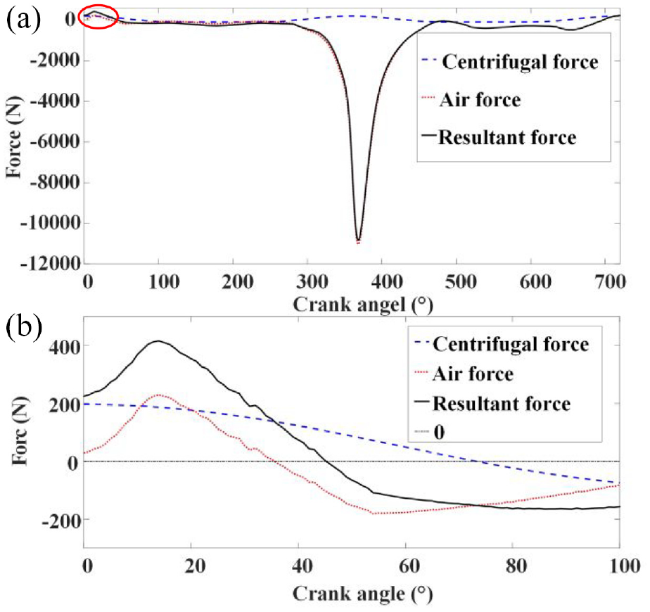
Dependence of force of piston pin on crank angle: (a) a whole work cycle and (b) local zoom.
In the crank angle range of 0°–45° and 694°–720°, the force on the piston pin is positive, and the direction of the piston pin force is upward. In the crank angel range of 46°–694°, the force is negative and in opposite directions. Combining Figure 7(c), it can be obviously observed that the moving direction of piston pin changed with the change of the force direction. The change time of piston pin force corresponded to the step change of acceleration time of piston pin. Therefore, the impact time of piston pin can be inferred from the change time of Z-direction force of piston pin.
From Figures 6 and 10, summarizing we can deduce the following conclusions. The necessary condition for ticking noise generation is that there was a clearance between the piston pin and the bearing and the direction of the force of the piston pin was changed in the Z direction. The impact time can be judged by referring to the crankshaft angle when the force of piston pin passed through the 0 axis. The simulation results showed that the impact intensity in the intake stroke was greater than that of the exhaust stroke, and the impact mechanism at intake stroke and exhaust stroke is the same, therefor, the step change of acceleration in the intake stroke was used to evaluate the intensity of the impact.
The same parameters were used in follow simulation of this work. Only a single parameter was changed for comparative simulation calculation.
Influence of different loads
In this section, the effect of different loads on the dynamic characteristics of the system was investigated. The dynamic performance was simulated with different combustion burst pressures while the output torques were 15, 30, 45, 60, 75, and 90 N.m, respectively. The Z-direction accelerations of piston pin corresponding to different loads at the intake stroke are shown in Figure 11.

Comparison of acceleration of the piston pin with different load.
It can be observed that the impact occurs at crank angle range 45°–90° in the intake stroke with 15–60 N.m load. The impact time is delayed and the impact intensity is increased with the increase of load between 15–45 N.m. However, the impact intensity decreases at 60 N.m, and the step change of acceleration is disappeared when the load is greater than 75 N.m.
Figure 12 presents the Z-direction resultant forces of piston pin corresponding to different loads at the intake stroke. It can be obviously seen that the Z-direction force increases with the increase of load at the beginning of the intake stroke. The movement pattern of the intersection of the resultant force on the piston pin and the 0 axis is the same as the step change of acceleration pattern in Figure 11. The impact time of the piston pin is closely related to the change direction of the force on the piston pin in the Z direction. The resultant force crosses the 0-value axis twice in the intake stroke while the load is 60 N.m, therefor, there are two impacts in Figure 11. As the load is greater than 75 N.m, the resultant force of the piston pin does not change direction, there is no impacting.

Comparison of resultant force of the piston pin with different load.
Figure 13 presents the hydrodynamic pressures at the impact time with 15, 30, and 45 N.m load and the peak values of the hydrodynamic pressure are 3.6 MPa(Δ), 4.9 MPa(□), and 8.3 MPa(◊), respectively. Combining with Figure 11, it can be concluded clearly that the impact degree is proportional to the peak value of the oil film hydraulic pressure.

Hydrodynamic pressure of the piston pin with different load.
The higher level of hydraulic pressure contributes to a greater radiation noise, it was proposed to reduce the noise by reducing the oil film hydrodynamic pressure at the moment of impact.
Influence of oil groove
In this section, the effect of oil groove in the bearing on the impact of the system was investigated. Taking the minimum oil film thickness as the goal, the parameters such as oil groove shape, width, and opening direction were calculated. Finally, the parabolic oil groove was designed, as shown in Figure 14, here 0° is the top of the bearing and 180° is the bottom of the bearing.

Schematic diagram of oil groove of connecting rod small head bearing.
Figure 15 presents the Z-direction accelerations of piston pin corresponding to with or without oil groove. It can be obviously seen that the impacting intensity decreases significantly with the oil groove.

Comparison of acceleration of the piston pin with and without oil groove.
Figure 16 displays the hydrodynamic pressures and asperity contact pressures of the piston pin at the impact moment. It is obviously that no asperity contact pressure no matter with or without oil groove, indicating that the impact was only generated between piston pin and lubrication oil, and the piston pin did not impact the bearing directly. The peak value of hydrodynamic pressure decreased from 3.6 to 1.9 MPa while the oil groove had been added on the bearing. The degree of impact between piston pin and lubrication oil was significantly reduced.

Hydrodynamic pressure of the piston pin: (a) with groove and (b) without oil groove.
Experimental verification
In this section, the proposed method was verified by experiment. Two engines with and without oil groove connecting rod were assembled respectively for comparative experiments. The engine was run on the test bench and the parameters were controlled as the same as simulation calculation during experiment. The engine speed was 1000 rpm, oil temperature was 90°C and the output torque was 15 N/m. A sound pressure sensor was mounted at 20 cm near the engine cylinder to record the noise signal, as show in Figure 17. The main devices are shown in Table 3.
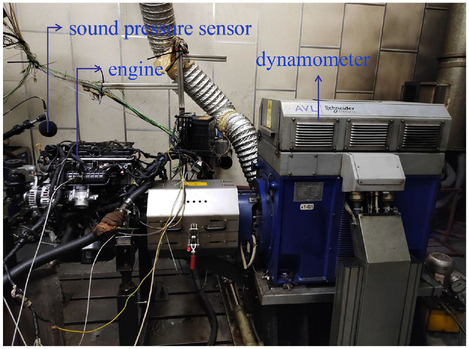
Test bench and sound pressure sensor mounting position.
Main devices for the experiment.

Figure 18 displays the sound pressures measured by the sound pressure sensor corresponding to with and without oil groove. Combining Figure 15, when no oil groove is added, the simulation results show that the absolute step change value of acceleration reaches 750 m/s2 around the crank angle of 55°, the experimental results show that obvious noise was detected between 55° and 60° crank angle. After the oil groove was added, the step change value of acceleration was reduced to 441 m/s2, and the noise was eliminated. This method is effective in controlling the clicking noise of the piston pin.

Comparison of the sound pressure with and without oil groove.
Conclusion
A multi-body dynamic model of crank connecting rod piston mechanism with lubricated full floating piston pin was established. The essence of the ticking noise was analyzed. In addition, a novel method was proposed to control the ticking noise, which was verified by experiments, and we make the following conclusions.
The oil film thickness on the connecting rod small head bearing decreased rapidly and the oil pressure increased submitted to the impact of the full floating piston pin. Then, in the Z-direction, vibration of the piston pin was generated and ticking noise was radiated. The necessary condition for ticking noise generation is that there was a clearance between the piston pin and the bearing and the resultant force direction of the piston pin was changed. At the same time, the time at which the ticking occur can be confirmed by referring to the crankshaft angle when the resultant force of the piston pin passed through the 0 axis.
The time and intensity of impact were affected by the load of the engine at the engine speed of 1000 rpm. As the load increased, the time of impact occurred at crank angle 45°–90° in intake stroke with the impact strength increased first and then decreased, the impact was disappeared while the load was greater than 75 N/m.
The impact strength of piston pin was found to be proportional to hydrodynamic pressure of the lubrication oil. Adding the oil groove on the connecting rod small head bearing, the peak value of hydrodynamic pressure decreased from 3.6 to 1.9 MPa. The degree of impact between piston pin and lubrication oil was significantly reduced and the ticking noise was even eliminated.
Footnotes
Handling Editor: Chenhui Liang
Declaration of conflicting interests
The author(s) declared no potential conflicts of interest with respect to the research, authorship, and/or publication of this article.
Funding
The author(s) disclosed receipt of the following financial support for the research, authorship, and/or publication of this article: This wok was supported by the Hainan Provincial Natural Science Foundation of China (grant number 520MS044), the National Natural Science Foundation of China (grant numbers 12174241).