
Abstract
Since Euler's original gyro-dynamic analysis nearly two and a half centuries ago, the use of multi-body dynamics (MBD) has spread widely in application scope from large displacement rigid body dynamics to infinitesimal amplitude elastodynamics. In some cases, MBD has become a multi-physics multi-scale analysis, comprising contact mechanics, tribo-dynamics, terramechanics, thermodynamics, biomechanics, etc. It is an essential part of all analyses in many engineering disciplines, including vehicle engineering. This paper provides an overview of historical developments with emphasis on vehicle development and investigation of observed phenomena, including noise, vibration and harshness. The approach undertaken is comprehensive and provides a uniquely focused perspective, one which has not hitherto been reported in the literature.
Keywords
Early historical developments
The history of multi-body dynamics (MBD) goes back to at least the Bronze Age when the Sumerians in Mesopotamia devised wheels by sticking solid axles through wooden discs. The use of these wheels to move carts/chariots provided the first example of a multi-body vehicle system. The history of the wheel, having been famously reinvented more than 50,000 times, parallels the developments of other mechanisms such as sextants, clocks, cam-followers, bearings, pistons, gears, etc. Most inventions and redesigns come about as the result of a need or an idea, not because of deliberate premeditation and scientific/analytical rigour.
Analysis and design evaluation is a relatively new endeavour since the sixteenth century and the trials of the polymaths such as Galileo Galilei (1564–1642). In those days, analyses were based on perspectives, geometry as an extension of movements of planets, and a form of synthesis in which Galileo excelled with his designs of machines and mechanisms. He followed in the footsteps of his fifteenth Century predecessor Leonardo Da Vinci (1452–1519). Leonardo proposed inventions such as his self-drive car (“vehicle”) and ornithopter 1 ; these being the first examples of multi-body systems in the Middle Ages. However, unlike all the previous polymaths, Galileo understood the concept of force and moment, as in centrifugal force and couple and other basic kinetics. Therefore, Galileo laid down the scientific foundation for the mechanical perspective.2,3
In Galileo's time, much of the dynamic analysis was based on observation, now termed as kinematics, which is the measurement of observed phenomena without regard to the underlying cause. It was observed by Kepler in 1609 4 that all the planets in the solar system revolve around the Sun in elliptical orbits of low eccentricity on the ecliptic plane (the Heliocentric system). This enunciation by Kepler and then Galileo put paid to the favoured ecclesiastical Earth-centred universe proposed by Aristotle (384–322 BC). In any case, the first observed multi-body system (the Solar system) engaged the attention of many in the ancient times through to the Middle Ages.5,6
The motions of planets around the Sun, as kinematic observations, were published in 1609 as Kepler's three laws of motion. 4 In 1687, Isaac Newton 7 showed that the elliptical planetary motions described by Kepler's laws conform to the underlying dynamics established by Newton's own three laws of motion and that of his law of universal gravitation. With the establishment of rigid body dynamics and its application to planetary motion, Newtonian mechanics was born, together with a proper description of the concepts of force and gravitation. Hence, planetary motion in the solar system became the first thoroughly investigated multi-body system.
Fundamentals of mechanical multi-body systems
In the realms of mechanisms and mechanical systems, the first application of rigid body dynamics was presented by Euler for single gyro-dynamics. 8 With this contribution, it became clear that dynamics of multi-body systems are subjected to constraints imposed by their assembly. This led to the generic formulation of constrained multi-body system dynamics by Lagrange. 9 A combined solution of differential equations of motion and algebraic constraint functions was developed. This approach has become the core of MBD analysis. Gammel 10 and Magnus 11 provided improved solutions to Euler's gimbal gyro-dynamics. Hence, the analysis of practical mechanical multi-body systems was born.
Other early developments, enabling the use of practical multi-body analysis, included improvements in matrix manipulation methods 12 for large and sparse matrices 13 and numerical integration methods for ‘stiff systems’ (those with widely split eigenvalues). 14
Large displacement-low-frequency vehicle dynamics (ride and handling)
In the case of vehicle engineering, MBD analysis was initially applied to vehicle ride and handling studies. It has been progressively used with larger degrees-of-freedom (DOF) systems for vehicle suspension analysis in industry using such computer codes as Automatic Dynamic Analysis of Mechanical Systems (ADAMS) and Dynamic Analysis and Design System (DADS). These codes provide automatic generation of differential-algebraic equations (DAE) and their simultaneous solution. Therefore, they are suitable for use in industry primarily for constrained rigid body dynamics, typically of suspension kinematics/dynamics, vehicle ride comfort analysis and vehicle manoeuvres/handling/road holding. Within the spectrum of dynamics’ phenomena, such applications may be classified as large displacement low-frequency events.
MBD studies were initially used for ride comfort and/or vehicle handling by Segel 15 and McHenry. 16 Other early applications of multi-body theory for vehicle dynamics were included.17–20 With the advent of detailed multi-body codes, large DOF vehicle models were developed with practical complex nonlinear suspension systems, and with the inclusion of tyre models21–27 for vehicle handling analysis. Complex manoeuvres were presented including lane-changes, slalom motions, J-turns, and cornering and braking.27–29 Hegazy et al. 27 presented a 94 DOF full-vehicle model and subjected it to various manoeuvres for assessment of vehicle handling in line with international standards such as International Standard Organisation and British Standard (BS). Figure 1 shows the modelled vehicle undertaking a lateral transient manoeuvre specified by BS AU 230. 30 Other researchers have considered various vehicle control features such as four-wheel steer (4WS) and Direct Yaw Control.31,32
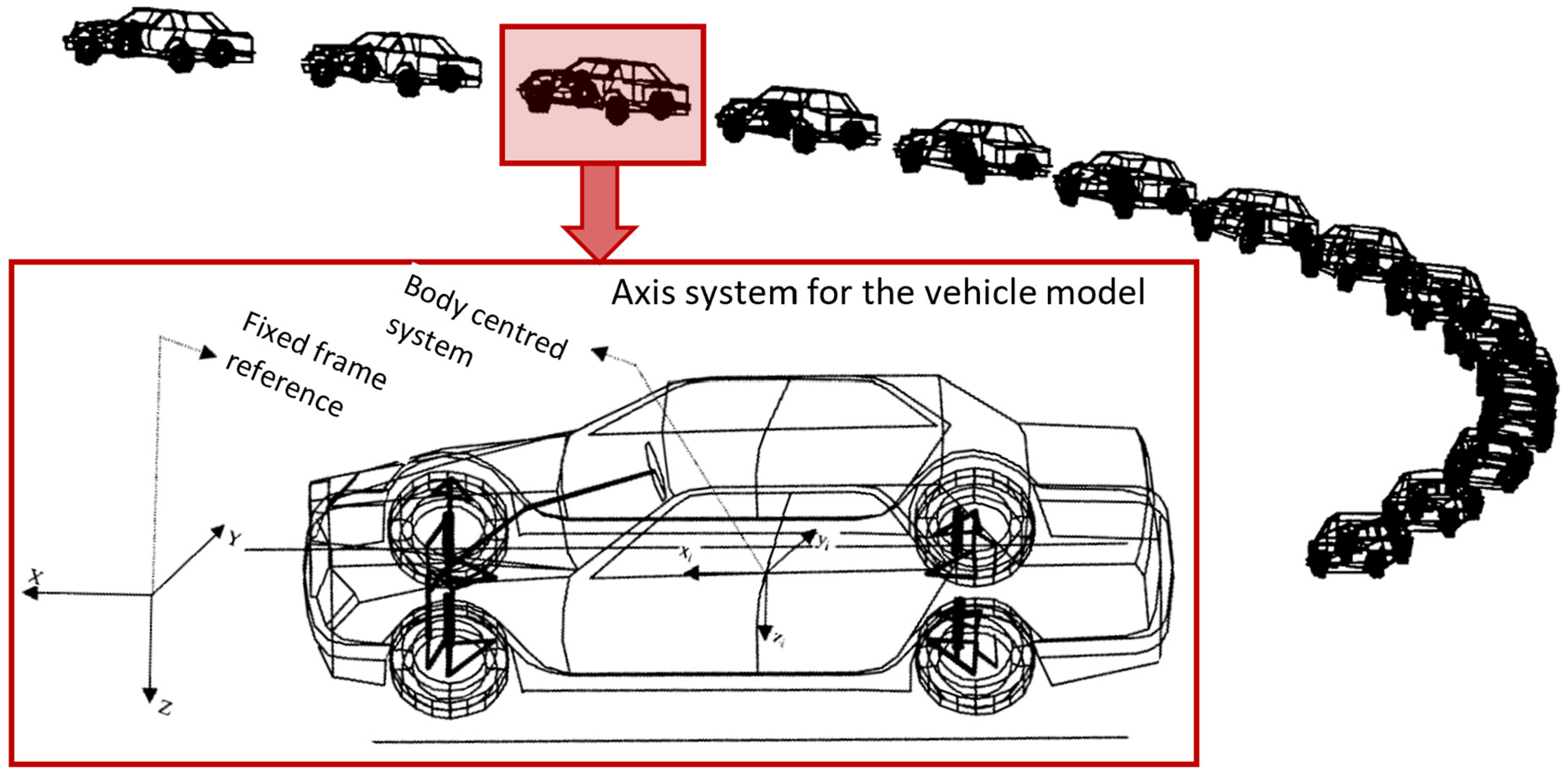
Animated lateral manoeuvre of a full-vehicle multi-body model at 0.8 g. 30
Nowadays, multi-body analysis plays an important role in the development and design evaluation of vehicles and their sub-systems. Such analyses include suspension kinematics and dynamics, elasto-kinetics, as well as vehicle ride comfort and road holding.19,33,34 Increasingly, a large number of additional load-case scenarios (other than those stated above) are taken into account in vehicle development. These include bounce, pitch and roll in traversing over road calming features (bumps), negotiating single bump events or falling into potholes.35–39 Harsh conditions such as kerb strike 40 are also considered. von Chappuis et al. 40 showed that a simple 7 DOF vehicle dynamics model would suffice for drive-over-kerb studies at various kerb strike speeds of up to 40 kph and for different kerb heights. The model included experimentally verified jounce bumper and rebound stop characteristics (Figure 2). The non-linearity and hysteresis of polymeric structures of jounce and rebound stops were included using experimentally verified mapping characteristics rather than the usual approach of simplified representations, using various viscoelastic analytical models. Therefore, fairly accurate prediction of vertical impact reactions of tyres, suspension mounts, jounce bumper and rebound stops were obtained (Figure 3). Such studies can help the design of chassis and suspension elements’ characteristics.
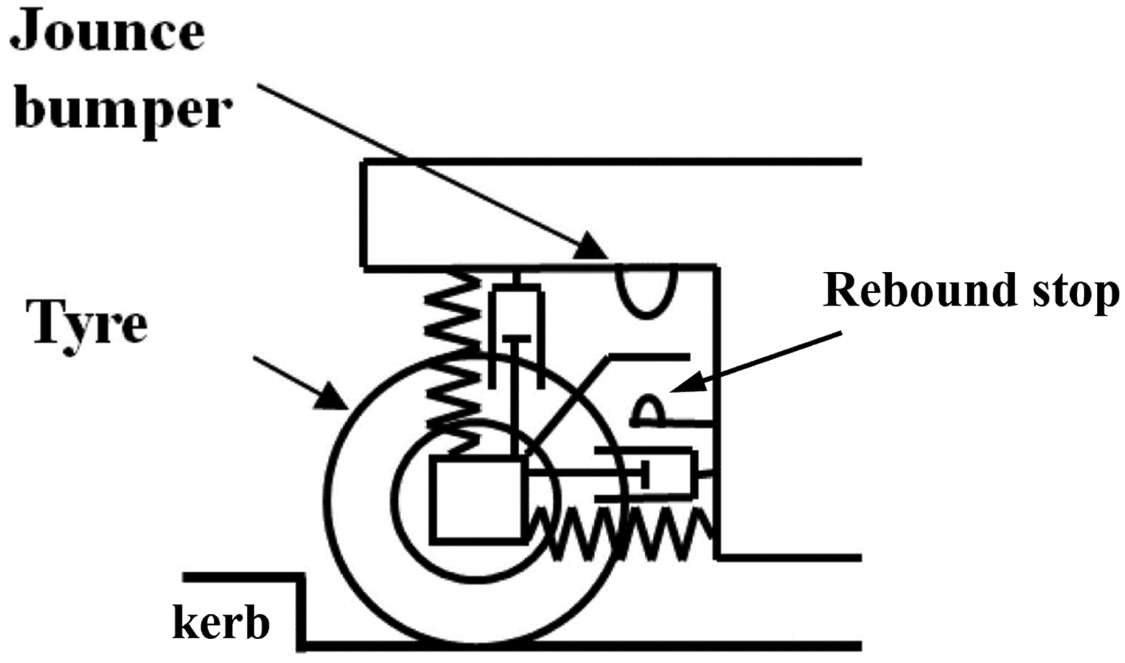
A simple vehicle model for drive-over-kerb study. 40
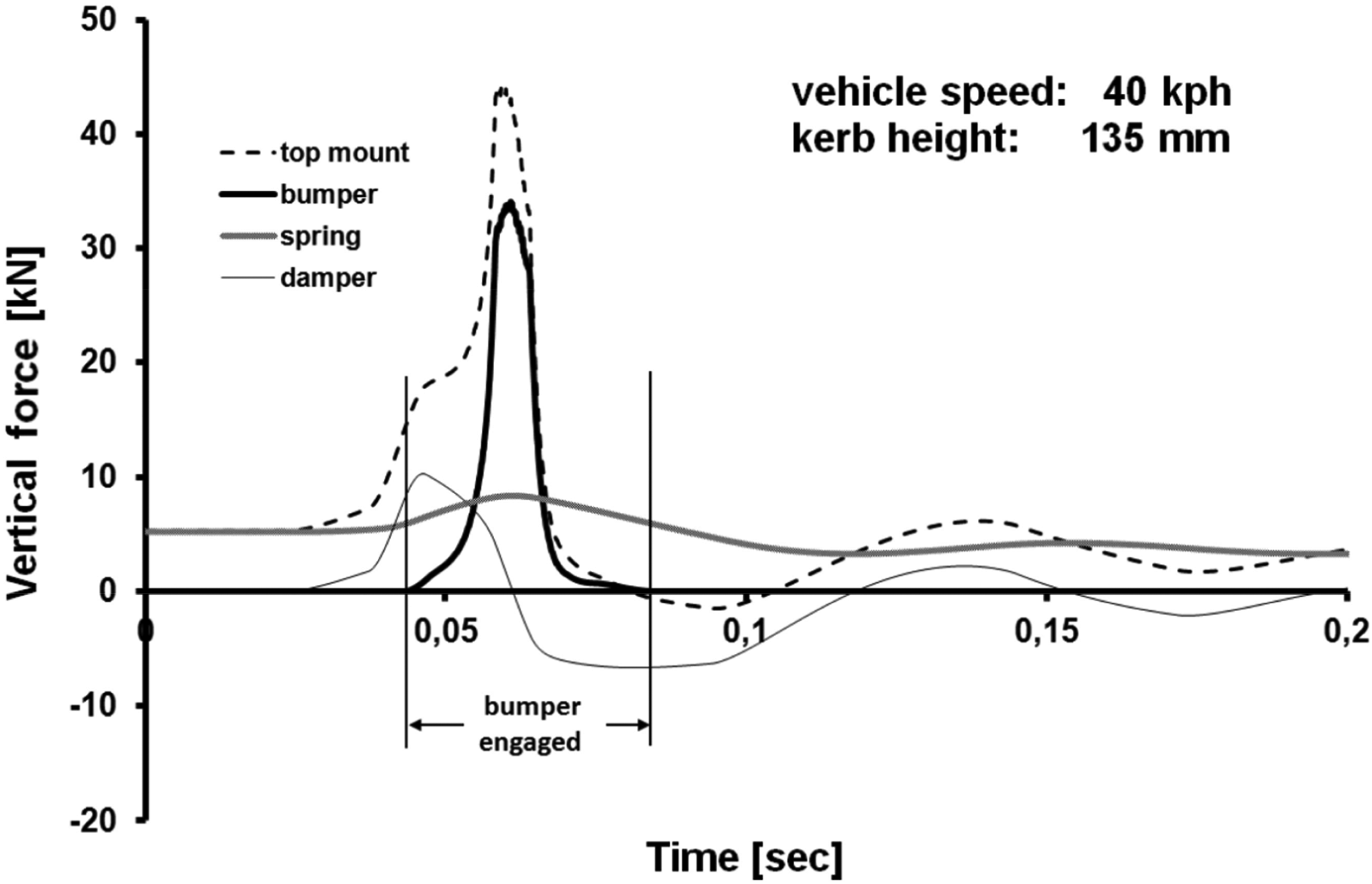
An example of predicted reactions of chassis and suspension elements in drive-over-kerb manoeuvre. 40
All these load-case scenarios affect kinematics of suspension, the applied forces acting on the chassis and suspension elements, as well as their structural integrity. Therefore, they can be used for design and design analysis of suspension systems’ structures, their integrity and control.41–46 All these studies necessitate the inclusion of detailed tyre models and elasto-kinetics of suspension compliance.
Two main types of tyre models have been developed. One is empirical, based on ever-increasing physical testing with purpose-built rigs, detailed testing procedures, data acquisition and regression analysis. Such empirical models lead to the creation of analytical expressions for tyre forces in terms of an increasing number of governing parameters/conditions. Good reviews of tyre modelling and testing procedures have been provided.47–51 Among the physical tyre models, the Magic-Formula tyre model is the most widely used. 49
The other type of tyre model is based on fundamental principles of contact mechanics with discretised elemental representation, relating the tyre reaction to localised deformation of the chosen element type. The elements usually include a small mass with stiffness and damping characteristics.47,52–57 These elements are generally termed brush elements and may have various elastic or viscoelastic characteristics. Some of these tyre models have been extended to include the effect of tyre carcass elasticity and inflation pressure.56–59 These additional features make the models more suitable for transient vehicle dynamics with combined slip, cornering and braking under extreme conditions, as well as riding over obstacles and kerb strikes. Figure 4 (a) and (b) show two types of brush models. In both cases, the tyre belt is discretised into small masses in contact with the road surface. Each element is an anisotropic bristle with carcass stiffness and damping properties which may follow any assumed viscoelastic model or simply use measured maps. To improve response characteristics under transient conditions, tyre belt behaviour is represented by elemental interconnections as shown in Figure 4(b).
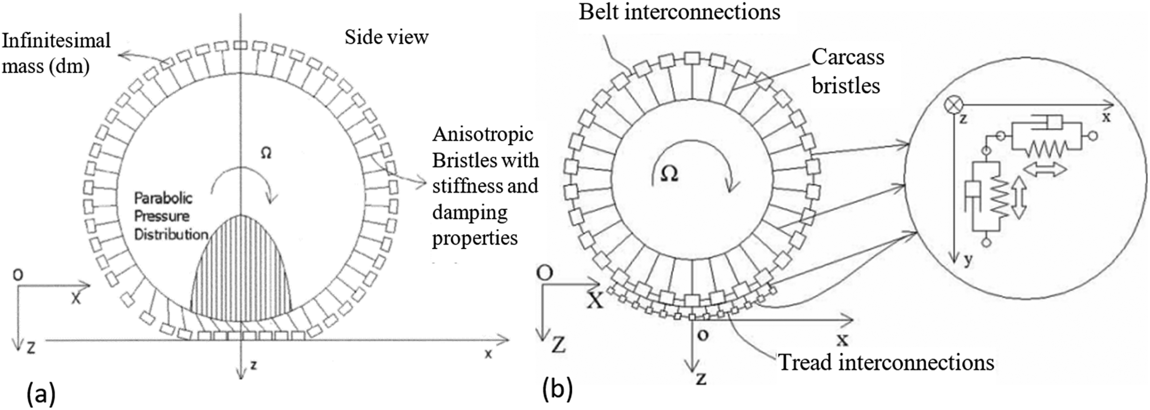
Figure 5 shows that brush models with belt interconnections better capture the response of the tyre, shown by the fluctuations evident at the onset of any transient manoeuvre. Soft materials such as tyres undergo creep even in rolling with slip, which sets up a transient response. Creep under slip stretches the tyre belt so that its periphery appears to be longer. This effect is captured by belt interconnections in the model of Figure 4(b). Belt, carcass and bead flexibility have also been included in some widely used empirical physical tyre models.60,61
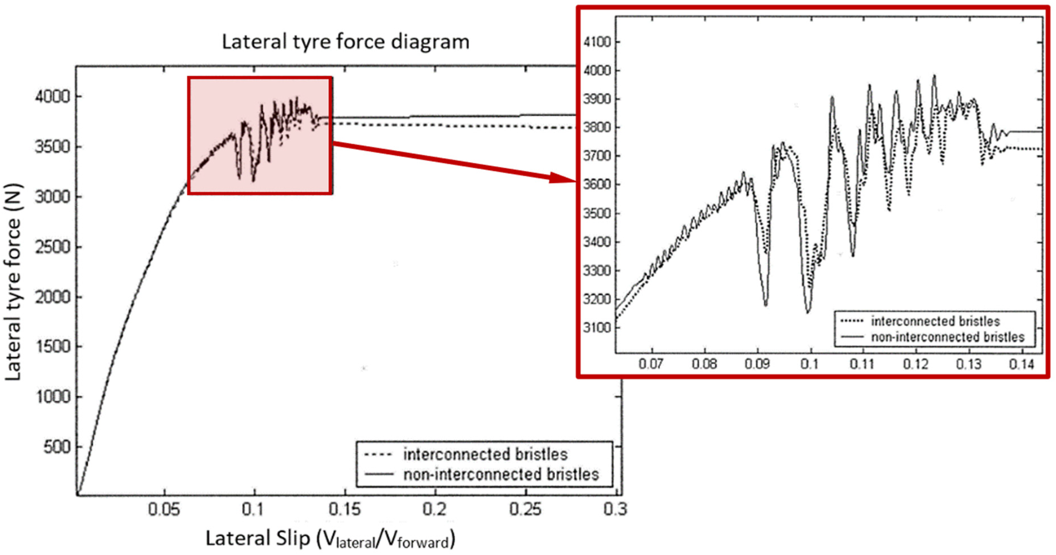
Tyre response characteristics under transient lateral slip conditions. 55
Friction can be implemented between the small-discretised masses and the road surface in order to represent tyre-paved road contact in the case of brush-type models. Coefficient of friction (rolling resistance) can be estimated based on an iterative recursive solution, or stick-slip motion, or different road surface topography, as well as on any changes in environmental conditions.53–55,62–67 Therefore, conditions leading to slipping can be investigated for vehicles travelling over terrains with some wheels running on unmade road verges, or ice or snow. Such conditions cause drag or slip, and are referred to as split-µ. 68 They can cause directional stability issues and tyre transience, when steering and braking, that require various control systems such as anti-blocking braking system, and 4WS.69–73
Off-road vehicles often run on soft and deformable surfaces (unprepared terrain). A detailed analytical method was proposed by Bekker74,75 for the parametric analysis of off-road vehicle performance. The most important aspect of off-road vehicle dynamics is the inclusion of pertinent tyre models. Soil sinkage under a wheel is caused by two independent effects: the pressure-sinkage orthogonal to the soil surface, and shear-tension-displacement along the direction of a rolling wheel (ruttage). Terramechanical tyre-soil interaction include either phenomenological analytical models with viscoelastic or poroelastic representation of the soil, or numerical models using finite element analysis.76–82 Various studies with off-road multi-body vehicle dynamics have been carried out on different soft soils such as sand and loam. This is in order to improve the tractive efficiency and optimisation of drivetrain components such as differentials and visco-lock systems.79,83–87
Within the area of vehicle handling, some other features can include the effect of aerodynamic forces (lift and drag), as well as unsteady conditions such as crosswind and side gusts.88–94 Hussain et al.
90
used the same detailed 94 DOF full-vehicle model in
27
to study the same cornering manoeuvre, but with the introduction of aerodynamic forces. The lift and drag characteristics of the vehicle were obtained using a 10% physical scale model placed in a wind tunnel prior to analysis using Computational Fluid Dynamics (CFD). The aerodynamic and multi-body vehicle handling co-simulation was compared with the same vehicle manoeuvre without the inclusion of aerodynamic action. Most modern saloon vehicles corner up to a lateral acceleration of 0.8 g, during which a body roll angle of
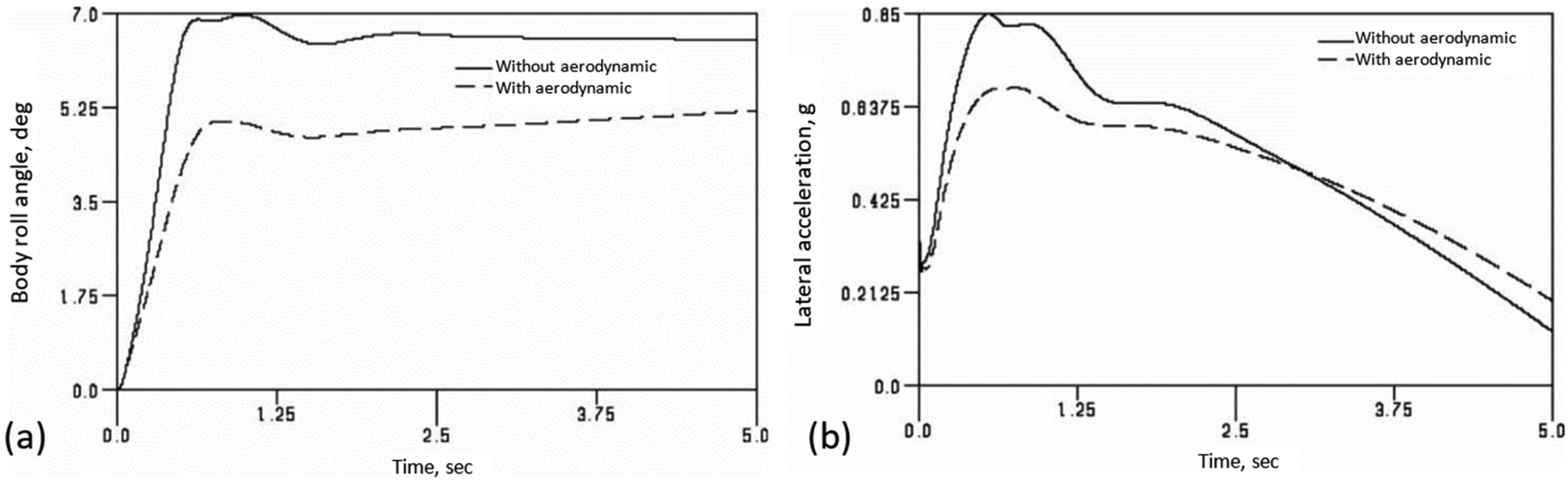
Vehicle lateral motion with and without aerodynamic interactions 91 : (a) vehicle body roll angle during the cornering manoeuvre and (b) lateral acceleration during the cornering manoeuvre.
Other additions to multi-body vehicle dynamic analysis have included vehicle occupants in the form of realistic human dummies/humanoids or more detailed biomechanical human skeletal models. These have been used for studies ranging from ride comfort to vehicle impacts. They also aid in the assessment of the performance of vehicle occupant safety features such as seatbelts and airbags by predicting physical injuries to occupants and pedestrians in different vehicle collision scenarios such as frontal, side or rear impacts. Representative literature for multi-body vehicle dynamics, including biomechanical issues are reported.95–106
Infinitesimal elasto-multi-body dynamics of powertrain systems
With improved methods of solution, including integration algorithms for stiff systems (widely split eigenvalue systems or broadband frequency response systems),14,24,107–110 multi-body analysis found its way into the multi-scale domain with integrated simultaneous dynamics across the physics of scale. In this domain, the flexibility of components should be taken into account. Impact dynamics and impulsive responses, typically in vehicular powertrain systems, follow stiff-system characteristics. There has been much research into the inclusion of component flexibility and contact/impact dynamics in multi-body systems. A representative sample111–116 deals with continuous contact, rigid, elastic and elastoplastic impacts of assembly of parts, with or without friction. There have been occasional reviews of such multi-body analyses.117–120 Most contact and impact models for multi-body applications have assumed dry rolling conditions 120 or stick-slip conditions. 121 However, in recent years lubricated contacts have also been taken into account.
Noise, vibration and harshness of clutches
Applications of MBD in stick-slip motion have included the study of untoward noise, vibration and harshness (NVH) phenomena such as judder of dry clutches.121–132 Clutch judder occurs as the result of stick-slip motion at the clutch friction lining interface, mostly during vehicle take-off (launch). It is the lowest natural frequency (rigid-body torsional-dynamics mode) of the clutch system which is usually in the range: 7 to 10 Hz.24,126,133,134 Centea et al.123,125 showed that clutch judder can occur as the result of two causes: (i) loss of clamp load in hurried release of clutch pedal by the driver (usually within 0.5 s) and/or (ii) a negative gradient of friction variation with interfacial clutch slip speed.
Figure 7 shows the angular velocities of the engine crankshaft (decreasing through gradual coupling with the drivetrain) and the rising angular velocity of the clutch pressure plate with an initial oscillatory transience. At full engagement, the two velocity variations act in unison. Figure 7(b) shows increased oscillatory behaviour with a negative gradient of friction lining material with increasing slip speed compared with that in Figure 7(a), enjoying a positive gradient. The tactile sensations of the driver's foot are more sensitive to an increased oscillatory response. The threshold for tactile perception of pedal oscillations depends on individuals and their footwear. Vehicle occupants notice clutch judder through its coupling dynamics with the fore and aft motion of the vehicle, sometimes described as a kangaroo-type hopping action. This motion is also a function of tyre contact patch longitudinal rolling resistance, the stiffness of the suspension mounts, as well as the stiffness of the tyre belt and carcass. Gradual wear of the clutch friction lining causes a negative gradient, effectively with a reduced coefficient of friction. However, a strong positive gradient can also lead to a rather overdamped clutch response with poor functionality (a ‘heavy’ or ‘hard’ clutch).
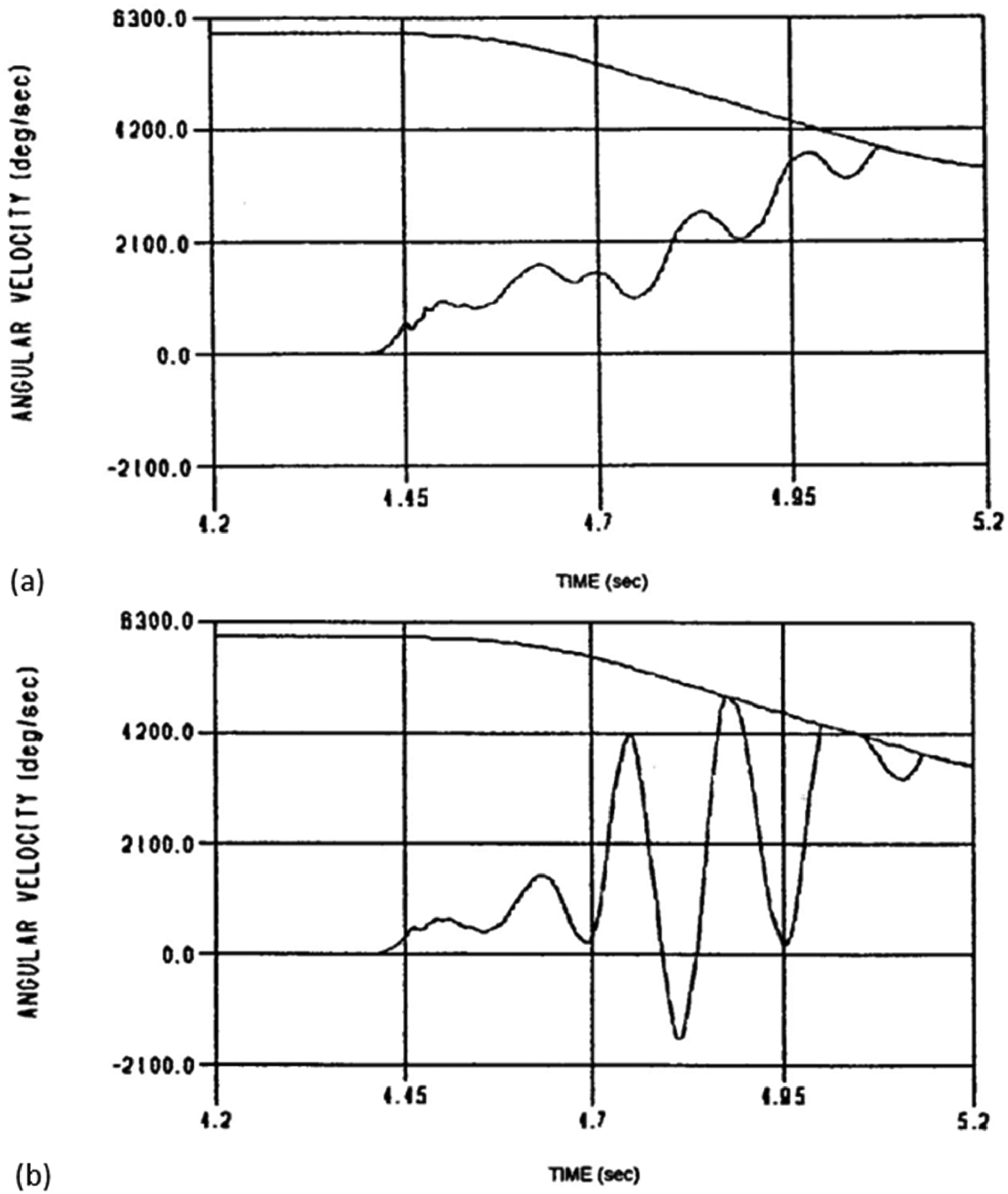
Clutch judder with (a) a positive gradient of clutch friction lining characteristics with slip speed and (b) a negative gradient of clutch friction lining characteristics with slip speed.
Most clutch lining materials exhibit a negative friction slope with slip speed. Therefore, discerning judder is a function of the severity of the negative slope and the sensitivity of the driver. Loss of clamp load occurs in all forms of manoeuvre, not only due to a hurried release of the clutch pedal. Therefore, for dry clutches, which dominate in the realm of most on-road vehicles, it is essential to determine the frictional characteristics of the interfacial clutch lining material with slip speed and achieved clamp load. Gkinis et al. 135 obtained such characteristics through representative tribometric measurements (Figure 8). The line AB shows a typical locus of transient frictional behaviour during clutch engagement reaching a full clamp load (in this case 8900 N for a typical light truck). Note that the characteristics show a negative gradient with increasing slip speed. Gkinis et al. 135 used such characteristics in an integrated thermal-dynamic analysis, indicating that even a single clutch actuation can lead to significant interfacial temperature rise. In turn, this rise in temperature significantly affects the path of engagement in the characteristics such as in Figure 8. This alters the MBD of the clutch mechanism.
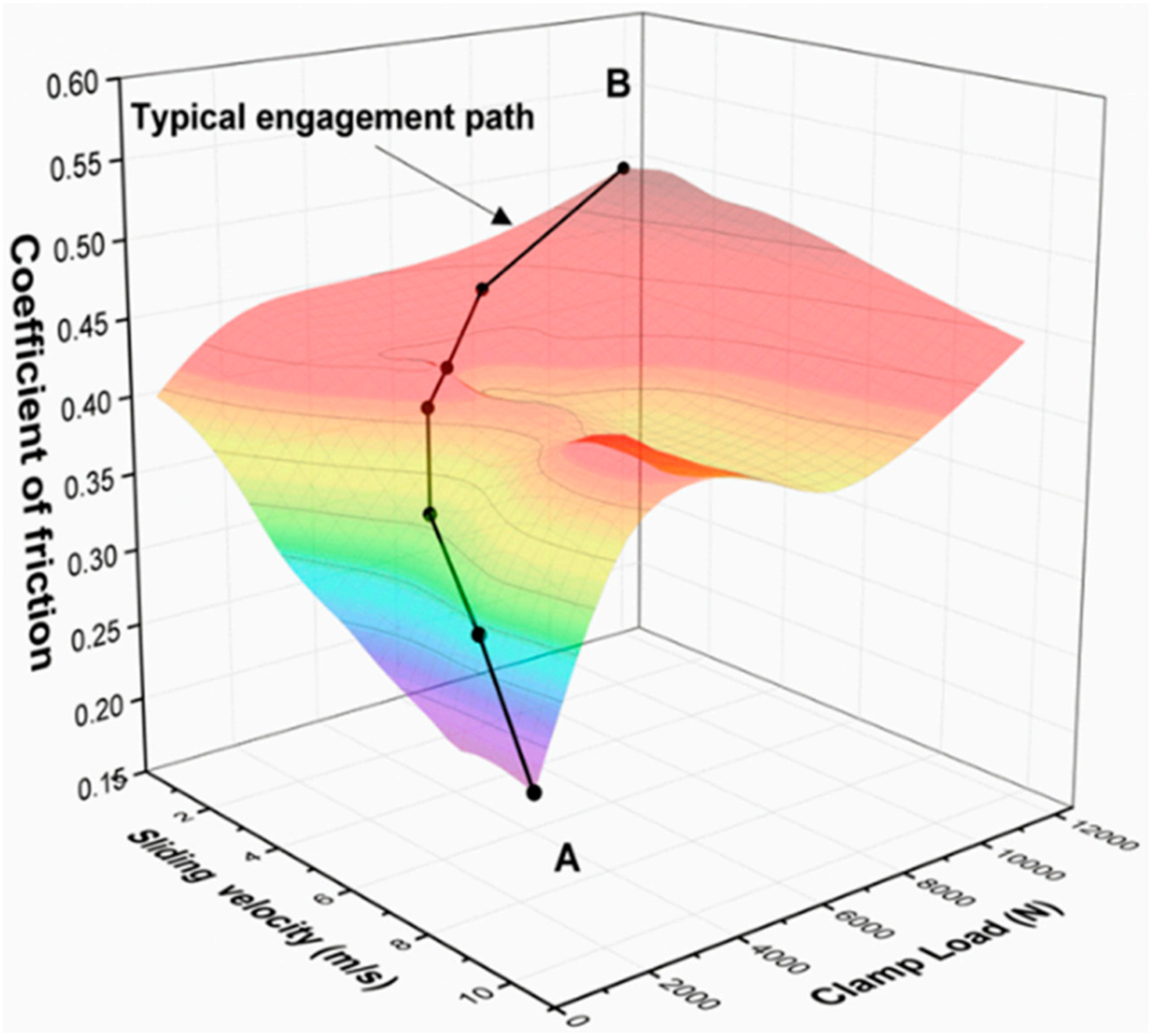
Clutch friction characteristics with slip speed and clamp load. 136
A modern application of the clutch system is to disconnect the engine from parasitic losses which occur in the powertrain system prior to the idling condition. This is an efficiency approach. It means that down-sized engines can be utilised, especially for heavy duty vehicles such as off-road vehicles (loaders, earthmovers and bulldozers). In this configuration, as the engine oil pressure builds up, a hydraulic piston applies a clamp load to the pressure plate and engages the clutch through friction discs (Figure 9). Although the hydraulic piston chamber is sealed, engine oil can potentially leak into the frictional interfaces due to seal dynamic failures or wear. This means that a multi-physics MBD model should be developed to investigate the effects of fresh or shear-degraded lubricant, which can cause localised stick-slip, on the performance of the clutch system. Dolatabadi et al. 136 measured the frictional characteristics of such lubricant-contaminated lining materials and used it in their MBD analysis. The torque capacity of the clutch with different oil leakage conditions affects the clutch engagement/disengagement processes, generally reducing the interfacial coefficient of friction, promoting judder. It was shown that full torque capacity is achieved for shear-degraded oil, whereas the torque capacity is decreased with any fresh-oil leakage (Figure 10). The engagement and disengagement initiation times and duration were also delayed due to the presence of lubricant in the contacts.
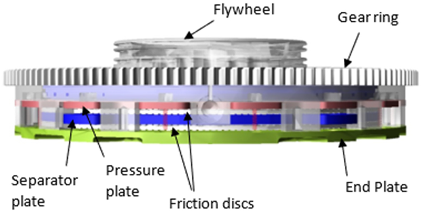
Multi-body dynamic model of the clutch system. 137
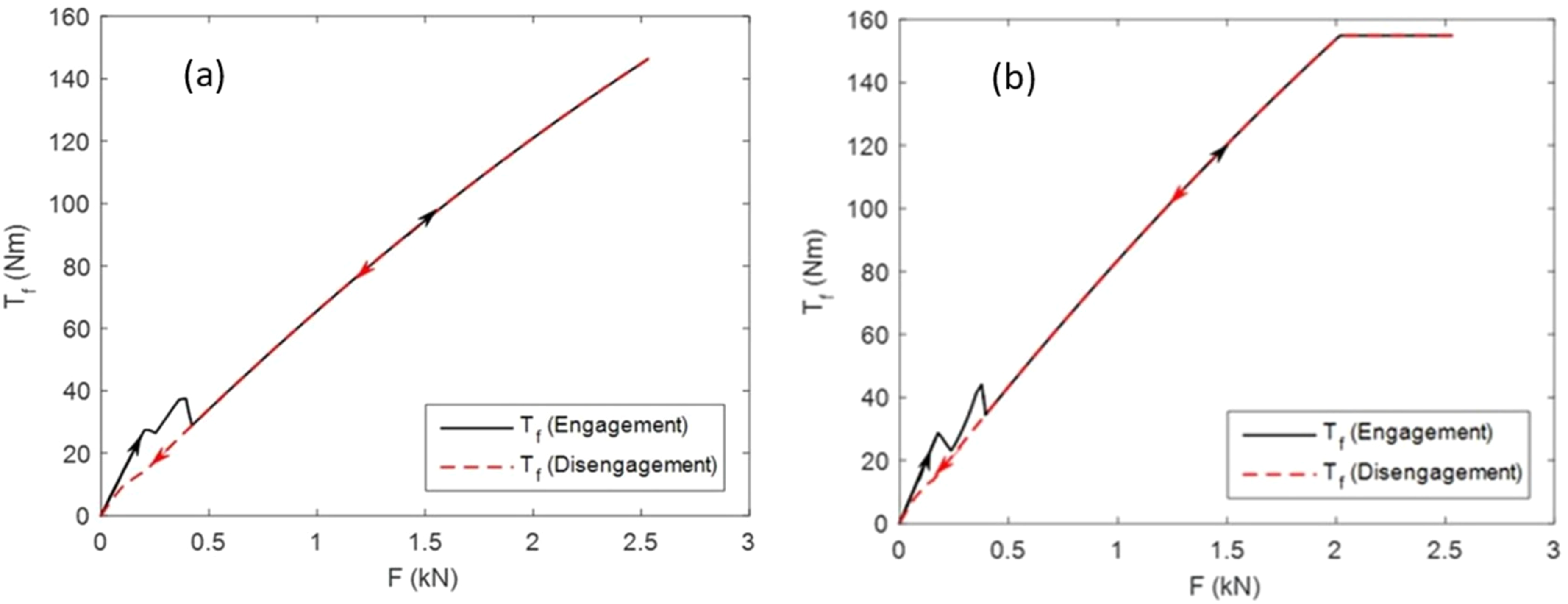
Variation of clutch frictional torque,
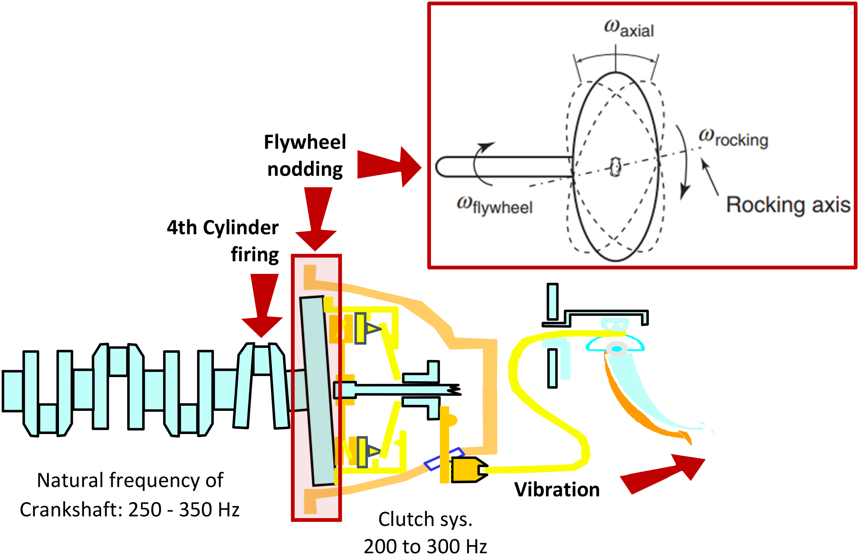
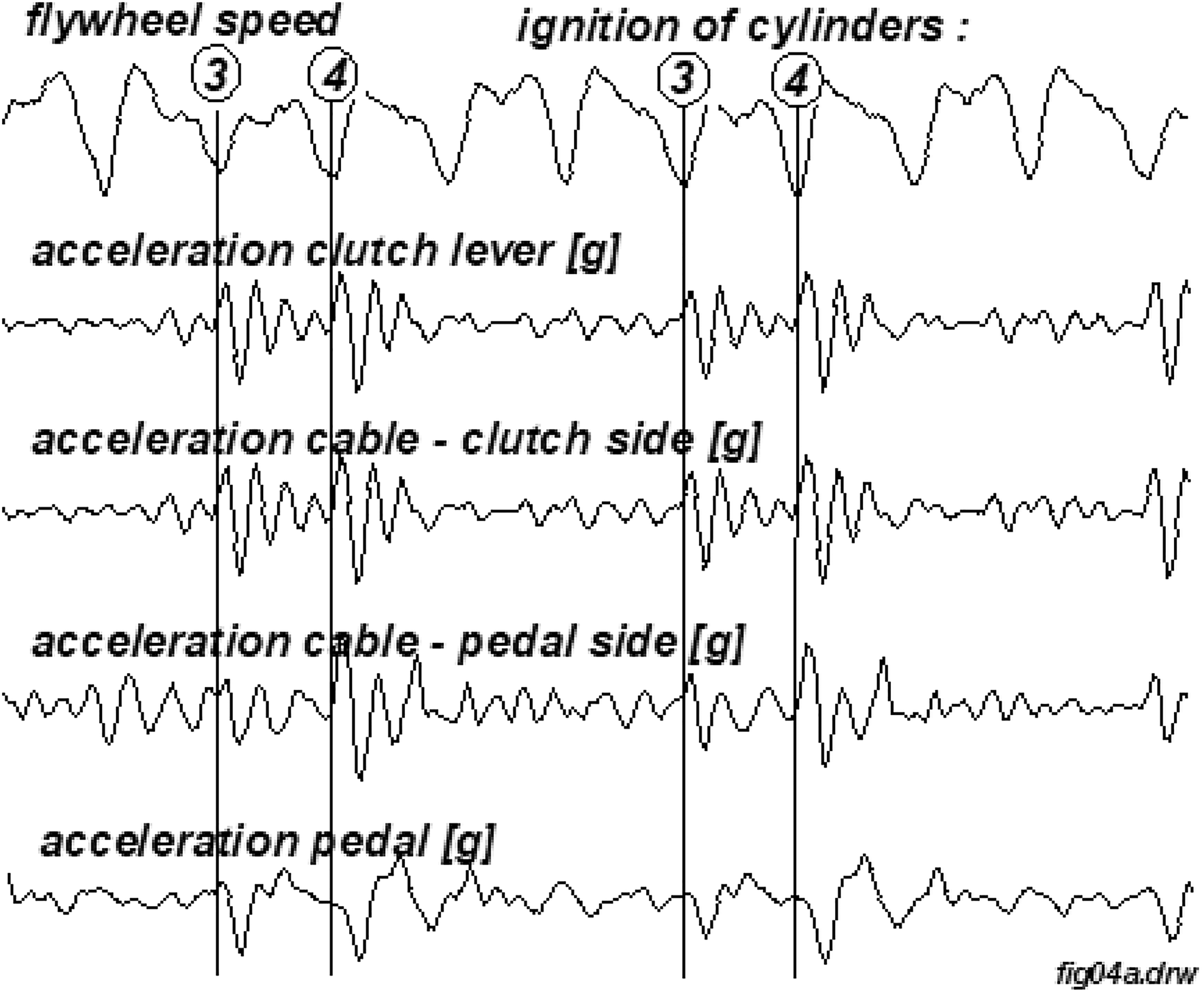
There are other higher frequency NVH issues in clutch systems, including a combined noise and vibration event during clutch pedal movement (during clutch engagement and disengagement). This phenomenon is referred to as in-cycle clutch vibration and is termed in industry as ‘whoop’, which is an onomatopoeic term for the emanated sound from the driver's footwell area.134,137 Kelly et al. 138 made a multi-body model of a cable-operated clutch system subjected to the motion of the clutch pedal (Figure 11). They noted that any potential conical whirl of the flywheel (‘flywheel nodding’) seen in the figure would impact the clutch friction disc during clutch actuation shown in the monitored vibration transmission path in Figure 12.
Multi-body model of clutch mechanism during engagement/disengagement.
Clutch whoop coincides with the natural frequency of the clutch lever, which is typically in the range 150 to 300 Hz for most saloon vehicles that use a cable-operated clutch. Therefore, one method of palliation is to use a mass-damper attached to the clutch lever in order to break the effect of frequency modulation.137,138
Figure 12 shows that for a four-cylinder in-line diesel engine, the firing of cylinders 3 and 4, nearer to the flywheel, accentuate the transmitting vibration signal, which is the underlying cause of clutch whoop. The whoop phenomenon is noted in modern diesel-operated engines with flexible crankshafts. Diesel engines have a higher torque output and with the modern concept of low weight-to-high output power ratio, torsional-deflection modes of flexible crankshafts are excited (natural frequencies 250–350 Hz). This leads more readily to the conical whirl of the flywheel (with the nodding motion shown in Figure 11 its inset). Therefore, in order to observe the whoop phenomenon in its entirety through numerical analysis, an elasto-multi-body model of the engine is required, coupled with the clutch actuation model. This is described later under the section ‘Tribo-elasto-multi-body dynamics of IC engines’.
Elasto-multi-body dynamics of driveline systems
Fore and aft motion of the vehicle is not only caused by the clutch judder phenomenon but can also take place through the application of throttle tip-in to accelerate, or throttle back-out to decelerate. These motions can lead to torsional oscillations of the entire driveline system, comprising the clutch, the transmission, the driveshaft, the differential and the rear axle in the case of rear-wheel-drive (RWD) vehicles. The lowest rigid-body torsional mode of the system is known as shuffle which couples with the fore and aft motion of the vehicle body in its lowest longitudinal vibration mode, known as shunt.122,139–141 Shuffle and shunt are usually low-frequency harshness-type motions in the frequency range 3–5 Hz for road vehicles and with even lower frequency oscillations (1–3 Hz) for heavy goods vehicles. This depends on vehicle body mass and driveline inertia, stiffness of suspension bushings and tyre-road traction characteristics.141,142 The phenomenon affects all vehicles whatever the source of propulsion: internal combustion (IC) engines, hybrids and electrics.143,144
Farshidianfar et al. 140 and Menday et al. 145 used an experimental rig, based on an RWD light truck's driveline (Figure 13(a)). The torque lever arm, connected to the flywheel through a low inertia disc brake, is displaced in order to compress the clutch springs and to take-up all the system lashes. The stored energy is then released within 80 to 100 ms in the form of an impulse torque of broadband frequency composition. This action excites a broadband response of the drivetrain system, from low-frequency rigid body shuffle oscillations of the driveline to high-frequency elasto-acoustic response of modern hollow (2 mm wall thickness) driveshaft pieces. Figure 13(b) shows the position of accelerometers and microphones placed for the acquisition of NVH signals.
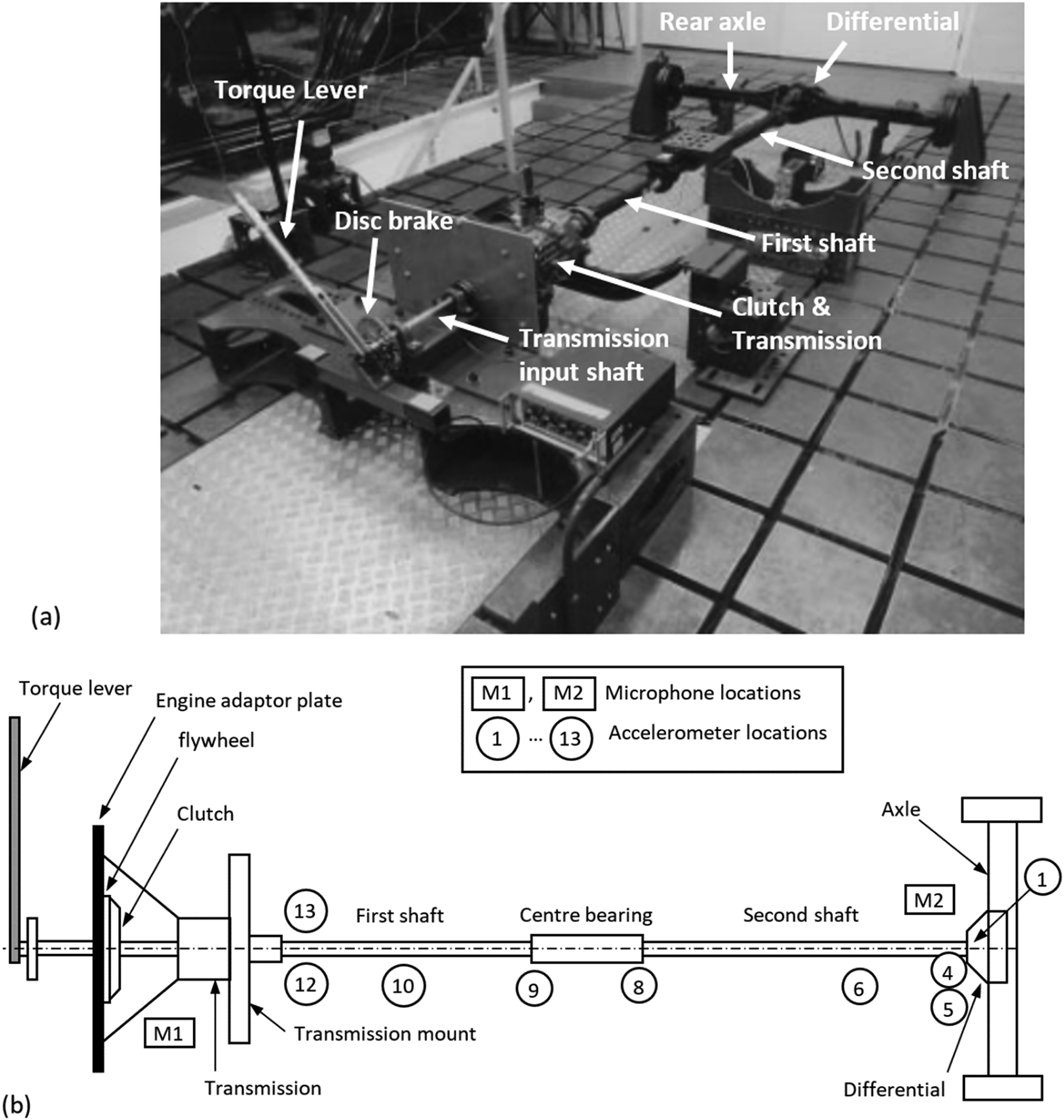
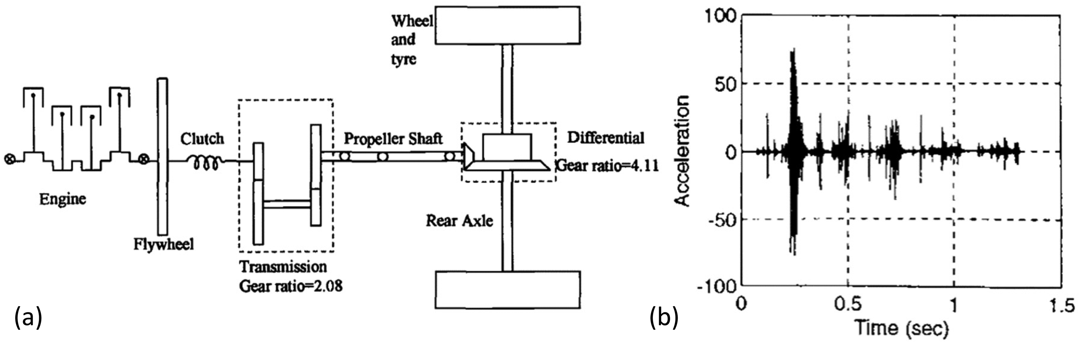
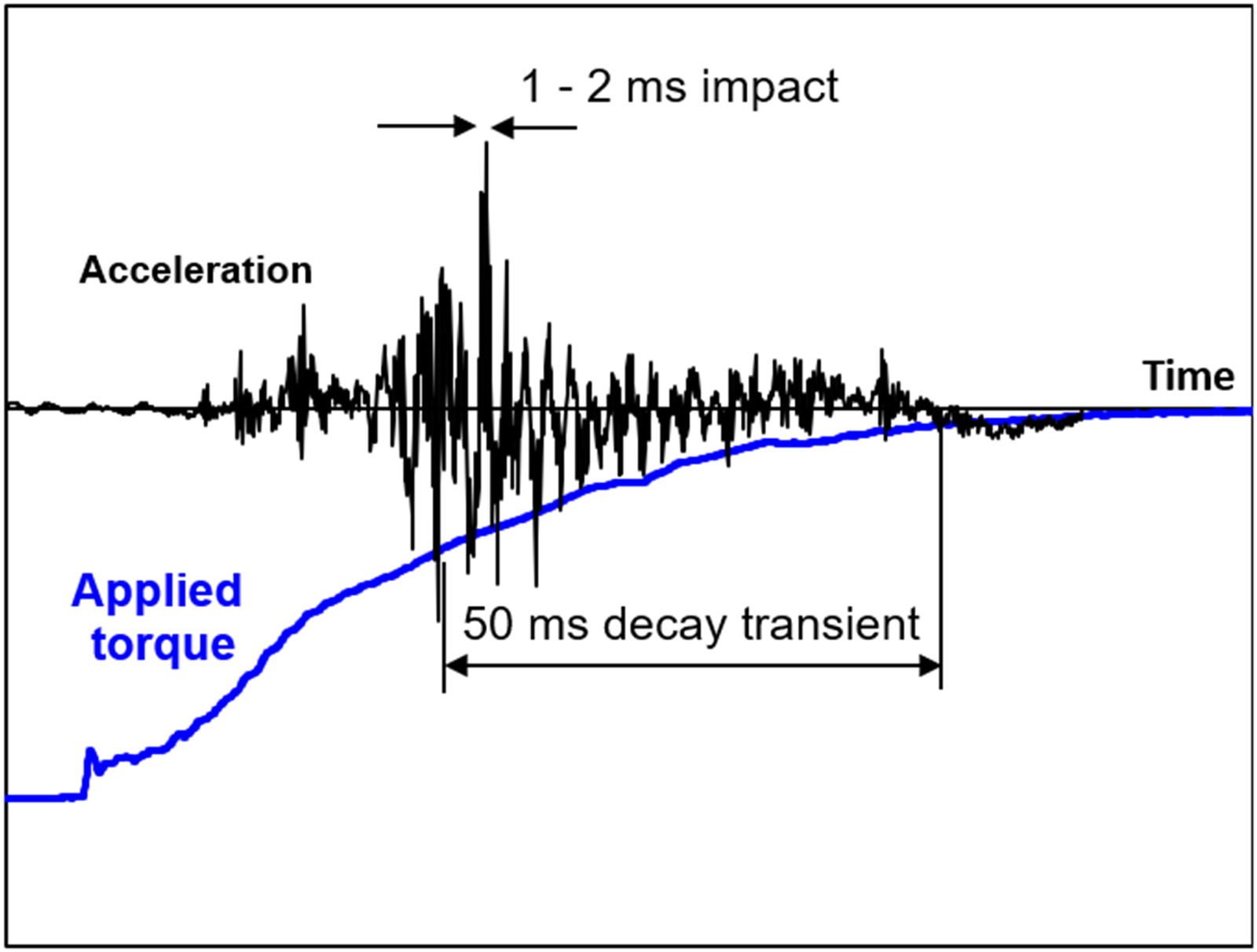
Figure 14(a) shows a model of the powertrain system by Farshidianfar et al., 140 primarily for the study of shuffle. Figure 14(b) shows a typical signal comprising a series of high-frequency oscillations occurring in a cyclical manner. 146 These high-frequency oscillations are the result of impacts in the lash zones (such as in the clutch and the transmission) with cyclic overall oscillations of rigid body driveline (shuffle). An overall fast Fourier transformation of the cyclic oscillations leads to the identification of shuffle response at around 3 Hz. 140 Figure 15 shows the contents of a window around one of the regions of high-frequency oscillations.145,147 These are the result of hard impacts in the lash zones, particularly the transmission gearing pairs (1–2 ms), first reported by Krenz. 148 The applied torque (in this case 150 Nm) is achieved through the movement of the torque lever arm (Figure 13(a)). With release of the lever the released energy travels along the driveline, inducing elasto-acoustic responses of thin-walled driveshaft pieces (tubes). Owing to the thinness of the tubes, they possess a high modal density (broad-band elastic modal responses), typically 500 to 5000 Hz.145–148 This elasto-acoustic phenomenon is referred to as clonk or clunk in industry (another onomatopoeic term as in the case of clutch whoop). It is particularly troublesome in trucks, buses, coaches and lorries with abrupt throttle tip-in or back-out or with sudden release of clutch.145,149,150 It also depends on the laden state of the vehicle (Figure 16). 151 The problem of clonk persists to a certain extent even with the use of dual-clutch transmissions to avoid sudden release.152,153 Although no component failure actually occurs with clonk, the metallic high-frequency sharp acoustic emission is very disconcerting to the driver, vehicle occupants and even to other road users.
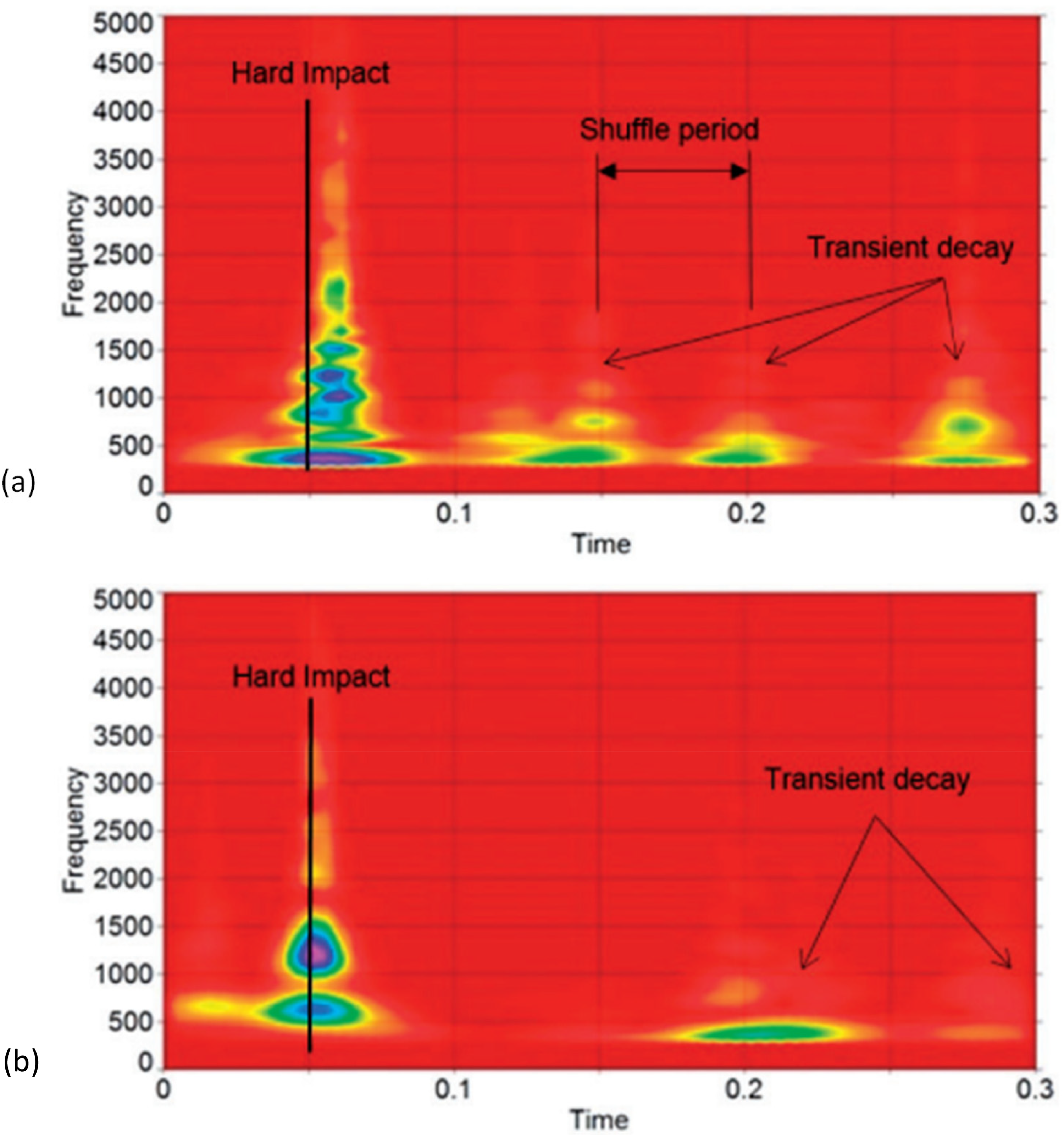
Wavelet spectrum of predicted elasto-acoustic response of vehicular driveline system from hard impulsive impact to transient decay (a) for an unladen truck and (b) for a half-laden truck. 152
The shuffle response predictions of the reported model of Farshidianfar et al. 140 agree well with the spectral analysis of the overall signal in Figure 14(b). 146 This shows that a simple rigid multi-body analysis can be used effectively to predict some powertrain NVH phenomena (Figure 17). As can be observed, the shuffle frequency for this RWD truck is measured and predicted to be at approximately 3 Hz. However, the signal in Figure 14 (b) contains repetitive high-frequency oscillations with a very short duration hard impact, followed by a transient decay (requiring windowing techniques to determine the high-frequency content). To predict the high-frequency elasto-acoustic clonk signal content, flexible MBD analysis needs to be carried out. Such models contain modal composition of the hollow thin driveshaft tubes. A flexible MBD model for the driveline system was first developed by Arrundale et al. 154 Figure 18 shows the driveline response when subjected to abrupt application of torque as in the sudden release of clutch pedal. The cycles of shuffle can be noted, with clonk signal with every cycle of shuffle, similar to the measurements in Figure 14(b). In the case of predictions there is no cyclic attenuation of the clonk events. This is because the model does not include material hysteretic damping or dry friction in joints and splines, which are present in practice. Nevertheless, the suitability of flexible multi-body analysis to predict high-frequency NVH events was then established by the contribution of Arrundale et al. 154
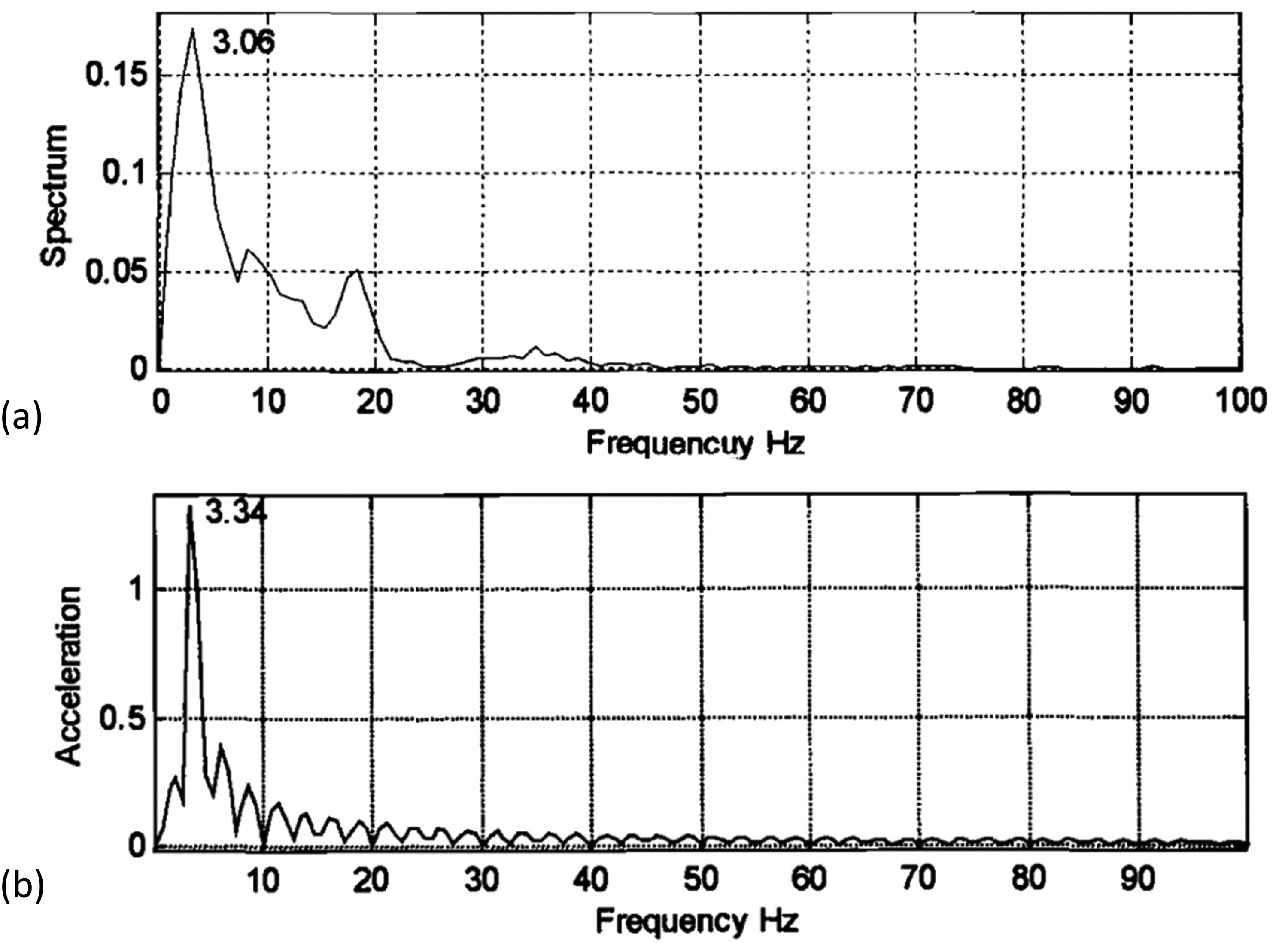

Cycles of shuffle with high-frequency impulsive action through zones of low lash rate zones (clonk). 155
Of course, the main purpose of any NVH analysis is to determine the underlying cause of any manifested phenomenon. This is followed by scenario-building simulations to achieve palliation or overall system refinement. Detailed elasto-MBD analysis of vehicular powertrain systems under the clutch-induced clonk condition was carried out by Theodossiades et al., 155 who used component mode synthesis156,157 to obtain the modal characteristics of the hollow driveshaft tubes.
Some predicted modal behaviours of the driveline system are shown in Figure 19. The excited mode shapes comprise relatively low-frequency bending modes through to torsional and combined torsional-deflection (flexural) modes. Some of the high-frequency flexural modes are efficient noise radiators as they coincide with the acoustic modes of the hollow cavities of the driveshaft tubes. These modes are referred to as the breathing (or bellowing) modes and are shown in Figure 19. Therefore, methods of palliation such as foam filling the tubes, or fitting them with cardboard liners/inserts can be used to break the propagation of high-frequency waves.
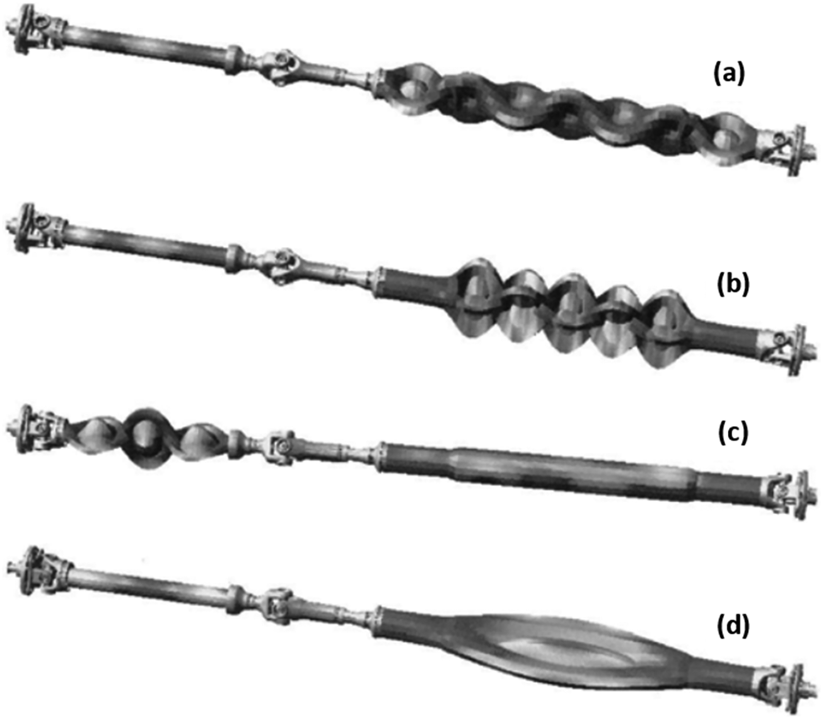
Magnified graphical scale of dominating mode shapes corresponding to (a) 3853 Hz, breathing mode, (b) 3550 Hz, breathing mode, (c) 3254 Hz, breathing mode, and (d) 617 Hz, breathing mode. 156
It is important point to note that as long as lash zones, such as clutch springs, meshing of transmission and differential gears, driveline splines and others exist, an impulsive action can result in the take-up of lash. Therefore, the abrupt release of clutch, sudden gear shift, or throttle tip-in or back-out can lead to elastic wave propagation. Meshing of transmission gears can initiate other NVH phenomena of concern in industry, such as whine of gears, commonly referred to as axle whine,158–161 gear rattle under various loading conditions, including engine idling, creep and drive rattle.162–166 Investigations regarding these phenomena show that in the study of impact problems through lash zones, it is essential to include the action of lubricant squeeze film motion as well as friction. Therefore, multi-body analysis should take into account inertial dynamics, structural elastodynamics, contact/impact mechanics, as well as other physics such as thermodynamics. As the multi-body investigations gradually extended into the area of powertrain NVH, analyses tended towards multi-physics multi-scale approach.
Multi-physics multi-scale extensions of multi-body dynamics
The first substantive application of multi-body analysis in vehicular powertrain systems was the multi-physics of the IC engine or its sub-systems. The investigation usually comprised inertial dynamics of crank-connecting rod-piston assembly with the inclusion of measured combustion variation with engine speed. The analysis also needs to incorporate lubricant reaction and friction of load bearing conjunctions such as the main crankshaft support bearings and piston–cylinder surface interactions. The first reported analyses addressed the more confined sub-systems such as tribo-dynamics of piston systems167–170 and valvetrains,171–176 some using Newton-Euler approach and some using constrained Lagrangian dynamics. The key point is that applications of multi-body analysis extended from large displacement low-frequency vehicle dynamics to infinitesimal-displacement-high-frequency domains. There have been many refined analyses for both piston–cylinder systems and valvetrains since early tribo-dynamic analyses. Recalling them all is outside the scope of this contribution. Instead, attention here is directed towards multi-physics of overall IC engines.
Tribo-elasto-multi-body dynamics of IC engines
During the 1970s to 1980s, the main focus of multi-body analysis for vehicle engineering applications was large displacement dynamics problems, such as suspension analysis, vehicle ride and handling manoeuvres. These issues have been addressed in the previous sections. With the advent of software codes such as ADAMS 13 and DADS, multi-body analysis became an almost routine exercise in the automotive industry. In the 1980s and 1990s, improved integration techniques 14 for high-frequency NVH events emanating from stiff-system characteristics enabled MBD to enter into the area of powertrain engineering. One of the very first applications was the complex issue of dynamics of IC engines.
Unlike the standard crank-connecting rod-piston assembly that is often used as a tutorial example, IC engines comprise important components such as crankshaft support bearings, big-end and small-end bearings. These bearings have often been treated incorrectly as mere joints (simply as holonomic or non-holonomic algebraic constraints). Inclusion of lubricated bearings and friction of interacting surfaces such as piston–cylinder leads to multi-physics analysis as described above. The system comprises different scales of interactions/motions from microscale in tribological conjunctions to infinitesimal vibration of flexible components such as crankpins and webs, and onto large displacements of piston, crankshaft/flywheel. This is truly a multi-physics multi-scale problem. Some of the first reported engine dynamics models177–181 have included at least some of these features, as well as incorporating measured combustion characteristics, which contains a broadband signature of the combustion process itself, depending on the two-stroke or four-stroke process. 24
A multi-body model of a single cylinder engine was developed by Boysal and Rahnejat178,179 in ADAMS. This was a detailed model that included hydrodynamics of the crankshaft support bearing. It also included hydrodynamic interactions between the piston compression ring and the cylinder wall. Therefore, a multi-scale tribo-dynamics model was created that also included thermodynamic solution of the combustion process. The instantaneous combustion pressure was obtained through the application of the first law of thermodynamics to the trapped air–fuel mixture in the combustion chamber. The Wiebe functions were used to determine the fraction of burned fuel, and Woschini correlation was employed to determine the instantaneous heat transfer coefficient. This was the first detailed MBD engine model. However, it did not include the effect of flexibility of inertial components. Torsional vibrations of the engine were obtained including the effect of four-stroke combustion signature, rigid body inertial imbalance and synchronous and asynchronous vibrations of engine bearings. The predicted spectrum agreed well with the spectral composition of a single cylinder engine, determined analytically or through the crank-star method established in. 24 The models in178,179 did not include the engine valvetrain system or the flexibility of the engine block and the crankshaft. These were included by Zeischka et al. 181 The valve train system was treated as a rigid cam-tappet contacting pair. Other early contributions considered the effect of component flexibility, such as an elastic camshaft 176 and lubricated cam-tappet contact.175,176 Ma and Perkins 182 developed an engine model with a flexible crankshaft-connecting rod-piston assembly. They also included a balancer shaft and engine support bearings. They compared their recursive-formulated integrated engine model with an ADAMS model of the same configuration and found reasonable agreement under firing conditions.
The key modelling aspect for modern engines has been the inclusion of crankshaft flexibility. This is because in the past two to three decades, with the adoption of the concept of high output power-to-lightweight ratio, a plethora of engine vibration phenomena have emerged. The vibration response of modern engines is now strewn with spectral contributions which had been palliated previously by cylinder phasing in order to reduce inertial imbalances and fluctuations in the combustion signature. 24 However, lightweight crankshafts made of materials of lower elastic moduli with thinner cross-sections or hollow structures are subject to combined torsional-deflection modes. Thus, the vibration spectrum of such engines contains half engine order multiples that do not exist in balanced rigid body rotation of stubby crankshafts. 24
Like many other structures, crankshaft flexibility was initially achieved by flexible crank-pins, discretised by a series of Eulerian beams. This approach is known as Transfer Matrix Method (TMM). An extended approach is to structure the crankshaft as a series of interconnected beams in three-dimensions, represented by Dynamic Stiffness Matrix Method.24,183,184 An initial contribution using TMM for a six-cylinder inline engine was reported by Arrundale et al., 185 taking into account the flexible crankshaft torsional-deflection modes at half engine orders. These spectral contributions are termed engine roughness. The work of Arrundale was followed by Ma and Perkins. 182
Kushwaha et al. 186 modelled a four-stroke four-cylinder engine, coupled to a clutch model with a flexible clutch-cover in order to study the clutch whoop phenomenon described above (Figure 20). They studied the engine vibration signals, both with a rigid crankshaft and a flexible crankshaft, with an appropriate cylinder phasing and firing order. For the rigid crankshaft, the spectrum of vibration at the position of the flywheel comprises only the second engine order and its higher harmonics as would be expected of a four-cylinder four-stroke engine 24 (Figure 21). For a realistic flexible crankshaft, all engine order harmonics, including half engine orders excited by the four-stroke combustion signature, are present (Figure 22). Therefore, it was shown that engine roughness as a source of NVH in modern vehicles is the penalty paid for improved fuel efficiency under the modern trend of high output power-to-lightweight ratio. The problem of exacerbated NVH with reduced inertial dynamics in favour of elastodynamics of flexible parts is likely to continue into the future with alternative sources of propulsion such as hybrid engines, electric vehicles and dual-fuel engines.
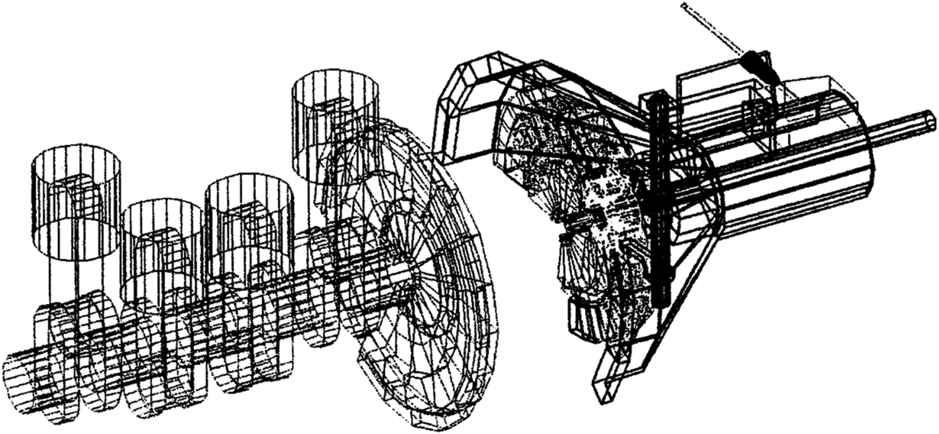
Combined multi-body engine and clutch system (integrated at the flywheel position). 187
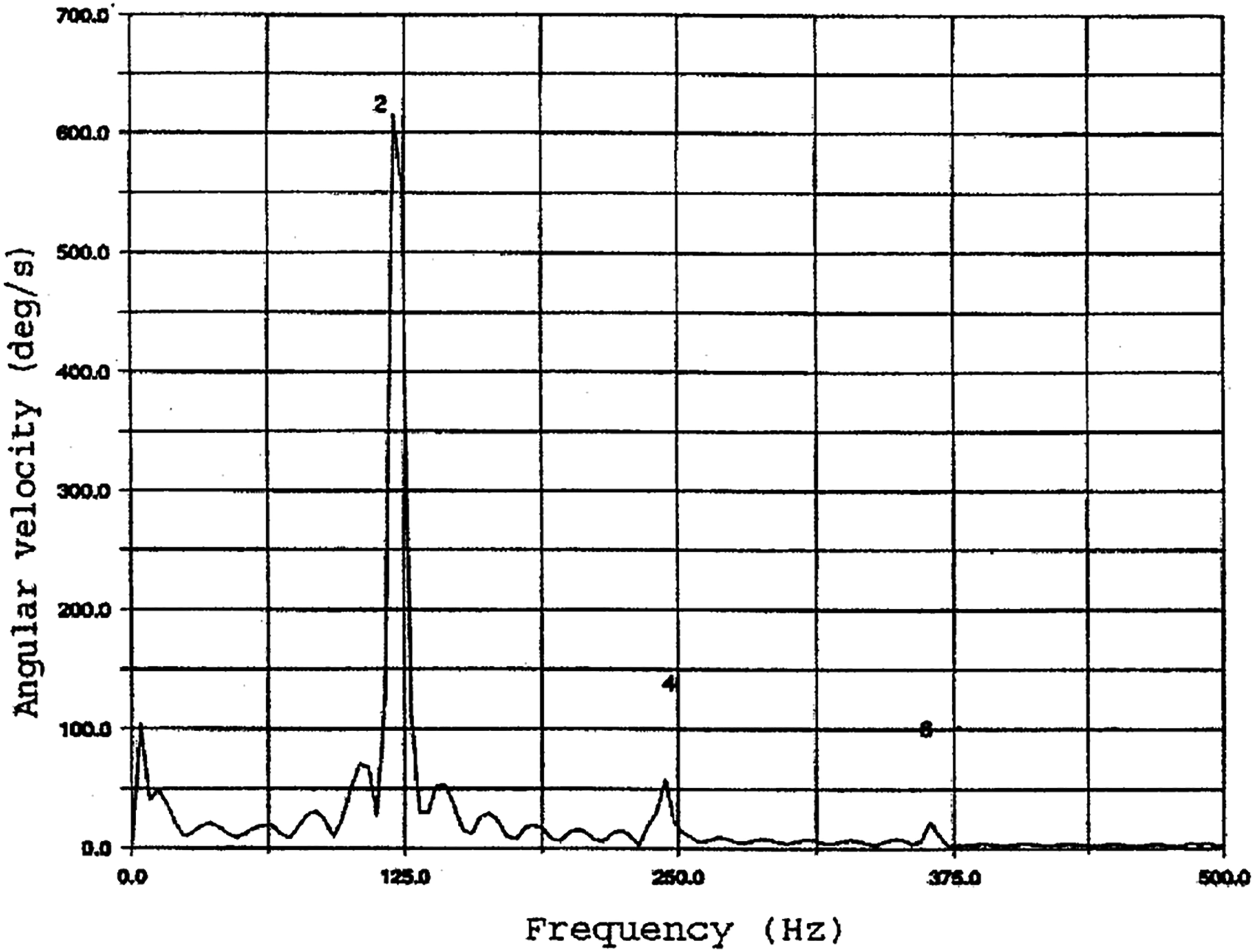
Spectrum of vibration of flywheel motion of a four-cylinder four-stroke inline multi-body engine model with a rigid crankshaft. 187
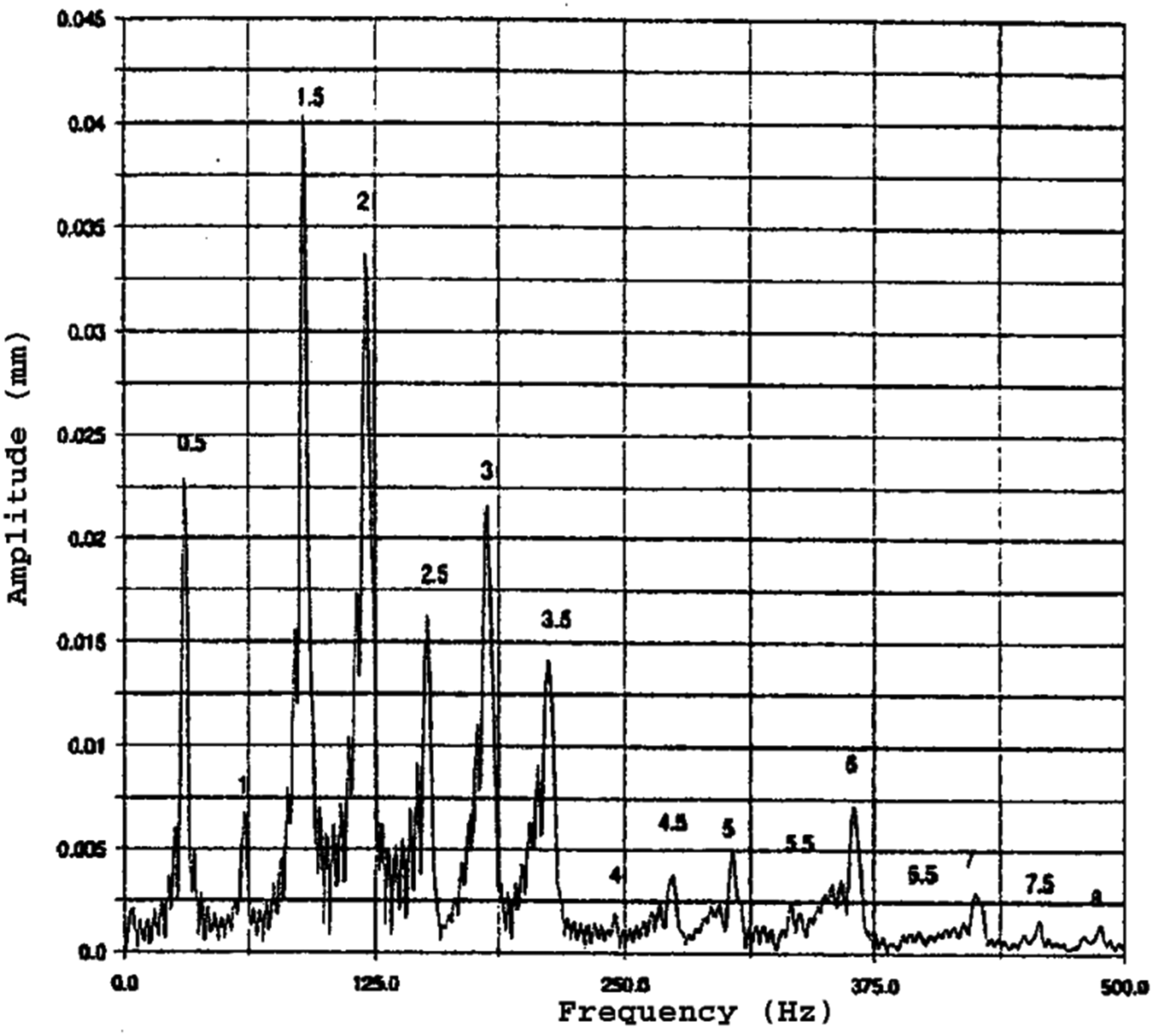
Spectrum of vibration of flywheel conical motion of a four-cylinder four-stroke inline multi-body engine model with elastic crankshaft torsional deflection. 187
Like the inclusion of component flexibility, friction generated by surface interactions significantly affects the inertial dynamics of engines. Guzzomi et al. 187 took into account the generated friction between the piston and cylinder surface. They showed that the accuracy of their predictions improved markedly when compared with the experimental measurements of engine block dynamics by Watling 188 using a devised test rig. Without friction in the analysis, the accuracy of predictions was compromised. Their study showed the importance of tribo-dynamics in engine applications. Perera et al.189,190 developed a tribo-elasto-MBD model, which included the flexibility of crankshaft as well as the tribology of piston–cylinder conjunctions (piston skirt and compression ring). They also included the main crankshaft support bearing. The authors carried out component mode synthesis156,157,191 to include the structural dynamics of flexible components such as the crankshaft and the flywheel.
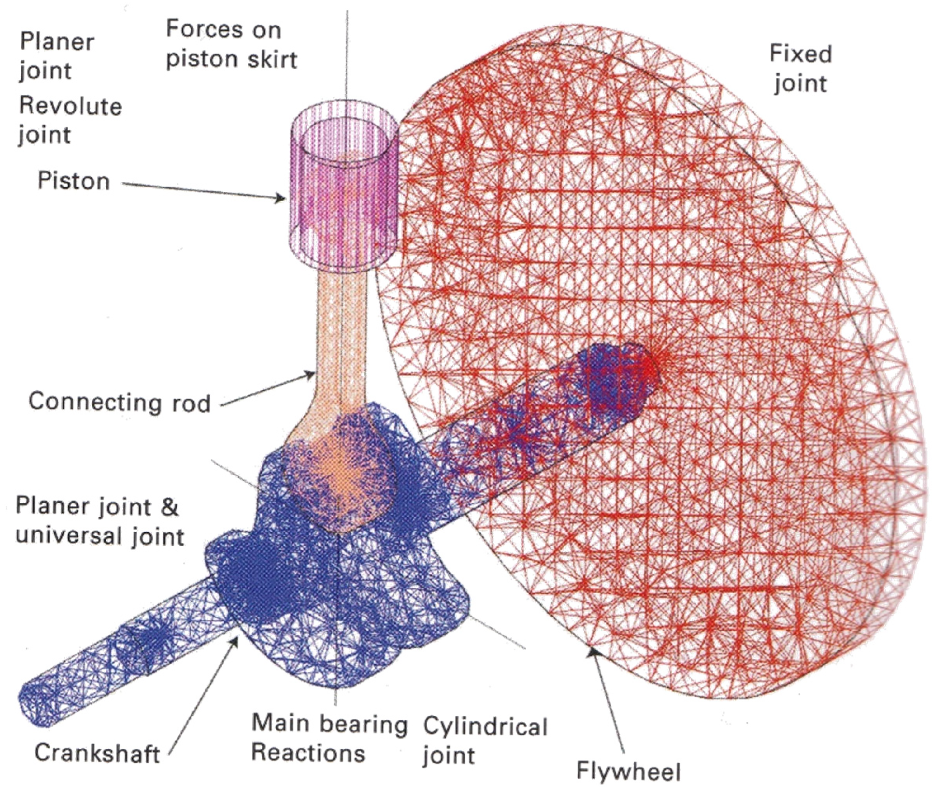
Figure 23 shows the model of a single cylinder Ricardo E6 engine developed.189,190 An interesting study carried out 190 concerns the relatively recent introduction of crankshaft offset instead of the traditional piston offset. Both offsetting methods are used to eliminate/reduce the secondary motions of the piston, which often lead to piston slap near the top dead centre. Secondary piston motions refer to its lateral excursions and tilting motion about its lateral axis within the confine of the cylinder. Figure 24 shows that, with relatively small crankshaft axis offset, there is reduced frictional power loss in the thrust and anti-thrust sides during parts of the piston cycle subjected to secondary inertial dynamics.
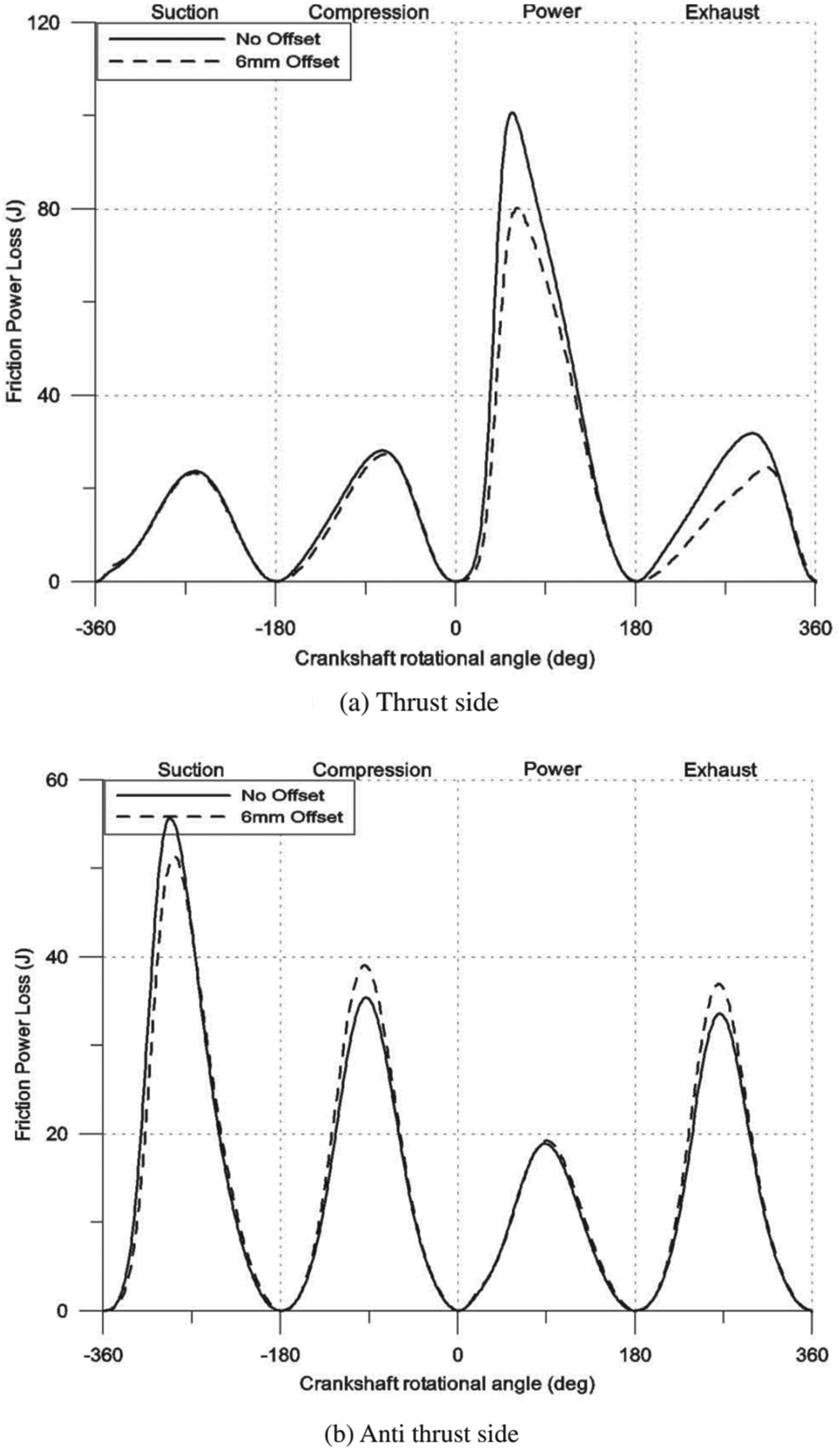
Frictional power loss at piston skirt to cylinder wall contacts with and without crankshaft offset. 191
Another integrated multi-body approach taking into account inertial dynamics, thermodynamics and friction as well as stiffness and damping torque was reported by Giakoumis et al. 192 They also showed that crankshaft stiffness and engine loading, depending on combustion and engine aspiration, plays a significant role in system dynamics. Their predictions agreed well with their experimental investigations of a single cylinder engine. Another engine dynamics model was presented by Karabulut 193 for the case of a two-cylinder four-stroke engine, including the engine block and mounts. The model studied the detailed design of engine components and their effects on the generated inertial forces transmitted to the vehicle chassis.
MBD of IC engines continues to attract attention even though there is a growing downturn in their future outlook. The current trend is to model vehicular propulsion in the context of hybrid electric-IC engines, as well as smaller engines acting as range extenders (such as single, twin or three-cylinder configurations).194–196 With the emergence of dual-fuel engines, such as hydrogen-diesel, particularly with potential use in marine and heavy vehicle applications, multi-body analysis will continue to play a role in the prediction of performance of various propulsion systems. Some recent analyses include.197–199
Concluding remarks
The foregoing shows that MBD analysis entered the application domain with four main developments: (i) automatic generation of equations of motion, (ii) solution of generated DAEs, (iii) sparse matrix technology and (iv) improved step-by-step integration methods. These developments led to MBD analysis codes such as ADAMS and DADS, which were initially used by the automotive and aerospace industries. This article covers applications of MBD in vehicle engineering.
In vehicle engineering, the original widespread use of MBD has been in relatively large displacement dynamics (suspension analysis, ride comfort assessment and vehicle handling/road holding). Increasingly, the role of component flexibility in MBD analyses has become commonplace (elasto-kinetics of suspensions, impacts, etc). Therefore, elasto-MBD has embraced component flexibility with resulting infinitesimal vibrations (modern MBD analysis is carried out in a multi-scale manner). Furthermore, the use of MBD in powertrain analysis has resulted in the inclusion of other physical phenomena such as contact/impact dynamics, friction in microscale and generated heat. Thus, the state of the art in modern multi-body analysis has become multi-physical and multi-scale. Over the past 25 years, the Journal of Multi-body Dynamics (JMBD) has been at the forefront of many developments, some of which have been recalled and expanded upon in this artitlce.
Footnotes
Acknowledgements
The authors wish to express their gratitude to the Engineering and Physical Sciences Research Council (EPSRC), Department of Trade and Industry (DTI) under the Vehicle Foresight Directorate, Ford Motor Company and Mechanical Dynamics Inc. for their financial support of various research projects, the findings of which are presented in this article. The financial support of Innovate UK and Caterpillar under Off-Highway Initiative is also acknowledged.
Declaration of conflicting interests
The author(s) declared no potential conflicts of interest with respect to the research, authorship, and/or publication of this article.
Funding
The author(s) disclosed receipt of the following financial support for the research, authorship, and/or publication of this article: This work was supported by the Engineering and Physical Sciences Research Council (grant number EP/D050332/1, GR/N36257/01).