
Abstract
This research was carried out to solve the problem of the reasonable characterization of the working load of the main bearing of a large tunnel boring machine (TBM) under complex engineering geological conditions and equipment working statuses. A typical telescopic swing main drive system is considered, and a characterization approach based on acquired dynamic characteristic parameters is proposed. First, the axial load Fa, radial load Fr, overturning moment Mk, and torque T are considered as the load indexes of the main bearing. The main drive load model is then developed, and the load indexes are expressed by exploring the relationships between each load index and dynamic characteristic parameters such as the pressures, displacements of the hydraulic cylinders, and torques of the driving motors. Finally, the load indexes are characterized based on a subsea tunnel shield project, representative engineering geologies, and characteristic load inputs. The results indicate that by taking into account the variable attitude of the main drive system, each load index can be expressed as functions of the pressures, displacements of the hydraulic cylinders, and torques of the driving motors. According to the variation of the dynamic characteristic parameters, the load condition of the main bearing during application is accurately characterized. Different geologies are found to correspond to different load levels; the load under the dolomitic limestone and filling karst cave strata is found to be almost 1.5–1.9 times greater than that under diabase, while the torque is almost five times greater. The proposed load characterization approach provides an accurate load input conforming to engineering practice for the design and selection of the main bearing.
Introduction
The main bearing is the core component of the main drive system of tunnel boring machines (TBMs) and the rotary support part of the cutterhead. It mainly accommodates different loads during the tunneling process, and transmits driving torque for the rotation of the cutterhead. Confronted with complex geological conditions, the performance, reliability, and service life of the main bearing can directly affect the construction efficiency, safety, and tunneling mileage.1–3 Typical difficulties4–7 encountered in construction, such as equipment malfunction caused by downtime, the eccentric load of the main bearing caused by uneven soft and hard composite strata, and high load requirements for the equipment under high water pressure, exert significant impacts on the load conditions of the main bearing. In the design, selection, and test loading of the main bearing, the load conditions are usually determined by experience. Moreover, there is no unified standard for the accurate characterization of the main bearing loads. Therefore, it is of vital significance to carry out load characterization for the main bearing of large TBMs based on dynamic characteristic parameters, and to obtain the load conditions during the service process to achieve the design, selection, and engineering application of the main bearing.
Relevant studies on the load conditions of the main bearing have been conducted by various researchers, generally from the perspective of the cutterhead load. The conventional approaches based on empirical equations or experimental models prove too rough to estimate the thrust and torque of the cutterhead under variable geological conditions.8,9 González 10 and Zhou and Zhai 11 explored the composition of torque under composite strata and extended the theoretical estimation model. Faramarzi et al. 12 employed the discrete element method to simulate the tunneling procedure and estimate the torque and thrust by applying actual boundary conditions for the model. Wang et al. 13 further investigated the cutterhead torque and its influencing factors while considering dynamic operation parameters, such as the cutterhead revolution speed, thrust speed, and main thrust force. Regarding load prediction, several models14–16 combining geological, operating, and structural parameters have been proposed to estimate the thrust and torque. In addition, a multi-step prediction method, 17 dynamic regulation model, 18 and hybrid deep neural network 19 have also been used for cutterhead torque prediction. Due to the considerable separation between the vertical sliding surface of the soil and the actual curved sliding surface, the traditional theory of arching in soils 20 underestimates the vertical load. For a deeply buried shield tunnel, the Terzaghi theory 21 overestimates the vertical earth pressure. Considering the distribution of the earth pressure and sliding friction, Chen and Peng 22 proposed an improved Terzaghi method in terms of a kinematic mechanical model to calculate the vertical load.
Shen et al. 23 concluded that shield-soil interaction affects the change of the shield attitude to some extent; they found that it could better reflect the load because the system attitude is taken into account. Via the establishment of a group-adjustable thrust hydraulic system, the change of the hydraulic cylinder thrust has been used to reflect the sudden change of the external load.24–26 Wang 27 and Wu et al. 28 proposed an electro-hydraulic control system to accurately control the attitude of the shield in composite geology, and the strategy of the least oscillation and quickest response, as well as the performances of different thrust systems, were evaluated. Tourajizadeh and Gholami, 29 Vallés, 30 and Chen et al. 31 regarded the current 3-PRS parallel manipulator model as having the same mechanism, and the kinematic parameters could be calibrated through a responding algorithm. Zubizarreta et al. 32 estimated the pose of the end-effector with the sensors to analyze the real-time performance. El-Wehishy et al. 33 considered that the cone angle limits remarkably affect the kinematic performance of the parallel mechanism, and they carried out the optimization of the symmetry axis direction of the spherical joint.
Without considering the actual complex geological conditions and real-time load changes, the existing load estimation, prediction, and parameter calculation methods based on the experimentation and calculation of the soil mechanics cannot accurately characterize the main bearing load. In this study, based on the main drive system with telescopic swing and spherical hinge components, the external load variation is reflected in real time by the parameters of the hydraulic cylinders, and the attitude variation of the main drive system is expressed by the 3-PRS parallel model. A novel approach for the comprehensive characterization of the characteristic loads is then proposed. This method can reflect the influence factors of different geologies under the actual construction conditions. A mechanical model of the main drive is developed to express the load indexes of the main bearing. In addition, the dynamic characteristic parameters of the equipment are considered important inputs to characterize the loads of the main bearing under complex geological conditions.
Structure and load indexes of the main bearing
At present, the main bearing used in TBMs is in the form of three rows of rollers; this type of roller bearing is characterized by low speed and a heavy load. 34 This study deals with the dynamic loads of main bearings with cylindrical rollers in three rows, namely two axial rows for the transmission of the axial force and the overturning moment, and one radial row for the transmission of the radial force. The structure and working force are shown in Figure 1.

The structure of a main bearing with three rows of rollers and its force system.
From the perspective of bearing loads, external loads can be summarized as the axial load, radial load, and overturning moment. 35 The torque applied at the inner gear ring is also a crucial parameter for the evaluation of the load conditions. Thus, the load indexes of the main bearing are determined as the axial load Fa, radial load Fr, overturning moment Mk, and torque T. Furthermore, load conditions in the force system can be expressed by different load indexes. To be specific, the axial load Fa is decomposed into FX, while the radial load Fr is decomposed into components FY and FZ on the radial action surface of the bearing. Moreover, the overturning moment Mk is decomposed into components MY and MZ on the radial surface.
Construction of the typical main drive load model
Based on a typical telescopic swing main drive structure, the load model is developed and analyzed to express the load indexes of the main bearing.
Structure and function of the telescopic swing main drive system
The routine main drive structure system is generally composed of a driving box, main bearing, driving plate, sealing ring, pinion, gear reducer, and variable-frequency motor. Moreover, the telescopic swing main drive system includes both telescopic and spherical hinge components. The telescopic components consist of 3 groups of 12 hydraulic cylinders, and each group is equipped with a stroke sensor. The spherical hinge components are used to adjust the attitude of the main drive system by rotating around the center point OC. The main drive structure and the layout of the hydraulic cylinders are shown in Figure 2.

The telescopic swing main drive structure and the layout of the hydraulic cylinders.
The driving model can be considered a typical three-legged parallel robot model to reflect the dynamic attitude. 29 The monitoring loads and motor input loads of the drive system are finally applied to the main bearing. These characteristics make it possible to express the loads of the main bearing based on the real-time position of the model.
Via the cylinder stroke sensor, the pressure sensor in the hydraulic oil circuit, and the frequency converter controlling the driving motor, the dynamic characteristic parameters such as the pressure, the displacement of the hydraulic cylinders, and the motor output torque can be conveniently acquired online. This is the first step for data processing and analysis to characterize the loads of the main bearing.
Mechanical analysis of the main drive system
To comprehensively reflect the load conditions of the main bearing, it is essential to develop the main drive load model for mechanical analysis.
The mechanical model of the telescopic swing main drive is first simplified. It is mainly considered based on the 3 groups of hydraulic cylinder push rods on the drive system, 12 groups of drive pinions on the inner gear ring, the supporting reaction force on the hinge center, the gravity of the structural components, and the comprehensive role of the frontal cutterhead. The mechanical model of the main drive structure is shown in Figure 3.
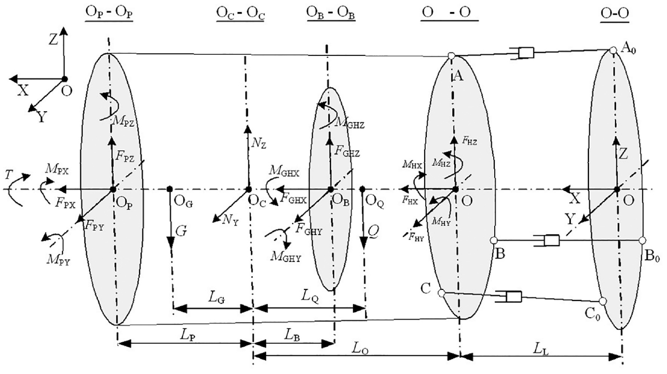
The simplified mechanical model of the main drive structure.
In the figure, the X-axis is the axial direction (i.e., the tunneling direction), and each of the YZ main planes is the radial force action surface. Specifically, OP-OP is the cutterhead acting surface, which acts on the total external force and torque, and OC-OC is the central surface of the spherical hinge, which acts on the supporting reaction force while the hinge center OC is treated as the analysis center. Moreover, OB-OB is the action surface of the main bearing (i.e., the meshing surface of each driving pinion and the inner gear ring), O′-O′ is the frontal surface of the hydraulic cylinders, which acts on the thrust and torque on the drive system, LL is the initial distance from the rear acting surface, and torque T acts on the cutterhead. It should be noted that the front self-weight G, the rear self-weight Q, and the distance from each center point OP, OB, and O′ to the hinge center are denoted by LG, LQ, LP, LB, and LO, respectively.
For the main drive analysis model, the equilibrium system is denoted at point OC, as follows:


where FHX, FHY, FHZ, MHX, MHY, and MHZ are the load components of the comprehensive force and the moment of the acting surface O′-O′ of the hydraulic cylinder, which can be expressed in combination with the tunneling parameters and attitude.
Moreover, FGHX, FGHY, FGHZ, MGHX, MGHY, and MGHZ are the total force and moment components of the surface OB-OB, which can also be expressed by the corresponding tunneling parameters. The other moments in the equations can be expressed as follows.


These moment arms can be obtained from the dynamic coordinates OP (xP, yP, zP), OG (xG, yG, zG), and OQ (xQ, yQ, zQ). The coordinate points are determined by the distance from each center point to the hinge center and the attitude of the main drive system. It should be noted that the position of the rear center of gravity is indeterminate. Thus, the unknown values of the equations are FPX, FPY, FPZ, NY, NZ, T, and LQ, which can be determined by combining the equilibrium system after considering the real-time acquired dynamic parameters and the system attitude.
Load expression of the main bearing
Via the analysis of the main drive system, the relationships between the main bearing load components and the external force under the spatial force system are calculated as follows.


The load indexes of the main bearing, namely the total axial force, radial force, overturning moment, and torque, are expressed as follows.


Relationship between the main bearing loads and the dynamic characteristic parameters
To establish the relationships between the main bearing load indexes and the dynamic characteristic parameters, the variable attitude of the main drive system should first be illuminated. The correlations between the cylinder loads, the driving gear loads, and the dynamic characteristic parameters should then be expressed.
Variable attitude of the main drive system
On the basis of the 3-PRS three-legged parallel robot model,29,32 the attitude changes of the hydraulic cylinders are considered as an example to solve the attitude changes of the main drive system. As shown in Figure 4, surface A0B0C0 (corresponding to surface O-O in Figure 3) is the fixed surface at the rear end of the hydraulic cylinders, and surface AkBkCk is the initial position surface at the front end of the hydraulic cylinders. A0, B0, C0, Ak, Bk, and Ck are the corresponding positions of the initial state, while points O and Ok are respectively the centers of the corresponding surfaces. Given the structural design parameters, their position coordinates can be directly obtained. Further, surface A′B′C′ (the acting surface O′-O′ in Figure 3) represents the frontal position at any time and point O′ is the center of the corresponding surface. Relative to the initial position, the end attitude mainly changes along the displacements SA, SB, and SC of each group and the rotation angles

The end attitude changes of the hydraulic cylinders.
The length parameters in Figure 4 are described as follows. LA0, LB0, and LC0 are the initial lengths of the hydraulic cylinders, and they are known quantities. LA, LB, and LC are the real-time lengths of the extended cylinders that can be expressed in terms of the displacements SA, SB, and SC, respectively. When the cylinders work, the lengths between the head and the end of the cylinders can be obtained from the rod length calculation conditions, as follows:


where
The position of point A′ is derived from point Ak by translation and rotation via homogeneous coordinate transformation36–40:

where s = sin and c = cos.
Similarly, the coordinate expressions of position points B′ and C′ can be obtained. It should be noted that this will not be repeated in this section. By substituting the coordinate expressions of A′, B′, and C′ into equations (25) to (27), the ternary equations of
Based on the previous analysis and calculation, the relationships between the variable attitude of the main drive system and the displacement parameters SA, SB, and SC can respectively be determined:


The variable attitude of the main drive system can be abbreviated as
Expressions of the cylinder thrust and moment
Among the dynamic characteristic parameters, the load parameters particularly refer to the pressures PbA, PbB, and PbC of the rod cavities of the cylinders in groups A, B, and C, respectively, and the pressures PrA, PrB, and PrC of the rodless cavities. Additionally, the design parameters are the cross-sectional area of piston rod Sb and the cross-sectional area of piston Sr. The working thrusts of each push rod are computed as follows.


Next, a hydraulic cylinder in group A is considered as an example to calculate the components of the thrust and moment.
The direction vector of the thrust is expressed as follows.

Thus, the thrust of the cylinder rod can be expressed as follows.

The components FA1X, FA1Y, and FA1Z of the thrust in group A can be obtained. Other groups can be similarly expressed.
The moment components are computed as follows.


Similarly, the thrust and moment of each hydraulic cylinder in groups B and C can also be expressed. The force system is simplified toward the center, and the components of the total thrust and moment of all the cylinders are then obtained as follows:


where L = X, Y, or Z represents the expressions of force and moment in different coordinate directions, respectively.
It can be deduced that the thrust direction is related to the coordinate of the end point, that is, the displacements of each hydraulic cylinder. The expressions of each component of the total thrust and moment consider the thrust direction and the position of the action point. In addition, they are related to the pressures PbA, PbB, and PbC in the rod cavities of each hydraulic cylinder, the pressures PrA, PrB, and PrC in the rodless cavities, and the displacements SA, SB, and SC of each cylinder. The expressions are given as:


where j = X, Y, or Z represents the expressions of the force and moment of the hydraulic cylinders on the drive system. The acting loads of the hydraulic cylinders are abbreviated as
Expressions of force and moment by driving pinions acting on the main bearing
The acting force and moment of 12 groups of driving pinions on the main bearing ring are calculated to obtain the loading condition of the main bearing surface. Considering one group of driving pinions as an example, the acting force on the inner ring is given as:

where RP is the pitch circle radius of the inner gear ring, T1 is the torque of the motor, and
Thus, the force and its components FG1X, FG1Y, and FG1Z at point G1 can be obtained.
Each component of the corresponding moment is computed as follows.


Similarly, the force and moment of other driving pinions on the main bearing can also be expressed. By simplifying the force system to the center of the main bearing surface, the components of the total force and moment in the X-, Y-, and Z-directions can be then obtained as follows:


where L = X, Y, or Z represents the expressions of force and moment in different coordinate directions.
The calculations of these loads mainly involve the torques Ti (i = 1, 2, …, 12), by considering the variable attitudes


where k = X, Y, or Z represents the expressions of the force and moment of all the driving pinions on the main bearing ring.
The acting load of the driving pinions is abbreviated as:
Relationships between the load indexes and characteristic parameters
In terms of the dynamic equilibrium equations of the mechanical model, the main bearing load indexes Fa, Fr, Mk, and T are given as mentioned previously. Combined with equations (15) to (24), (29) to (31), (42) to (43), and (50) to (51), and considering the variable attitude of the main drive system, the main bearing loads can be expressed by the relationships of the dynamic characteristic parameters, as follows.


After considering the variable attitude of the main drive system, these load indexes are expressed as the related force and moment. In other words, the relationships between the dynamic loads of the main bearing and the displacements of each hydraulic cylinder SA, SB, and SC, the cylinder rod cavity pressures PbA, PbB, and PbC, the rodless cavity pressures PrA, PrB, and PrC, and the driving motor torques Ti (i = 1, 2, …, 12) are constructed.
Engineering application
The previous description of the load indexes is mostly theoretical. To further accurately characterize the actual working loads of the main bearing in practical engineering, the processing of tunneling data and the analysis of geological characteristics must be considered. Relying on a subsea tunnel shield project and complex engineering geologies, the actual load condition of the main bearing in construction applications is further determined.
Engineering geology overview
A subway shield tunnel project in the sea area along a route with a length of 2310 m is considered. The tunnel adopts a Φ12 m slurry shield TBM equipped with a telescopic swing main drive system. The maximum gradient of the line is 28‰, while the minimum gradient is 2‰. Intuitively, the longitudinal gradient of the line presents a “V” shape, as shown in Figure 5.
The route map of the subsea tunnel.
The subsea tunnel mainly passes through moderately weathered dolomitic limestone, diabase, a small amount of fully weathered limestone, and karst cave strata. The tunnel has the characteristics of a super section, a large buried depth, high water pressure, and a long distance. When the tunnel line passes through the upper-soft-lower-hard composite stratum, it is difficult to maintain the established shield attitude, which results in the serious eccentric load of the main bearing.
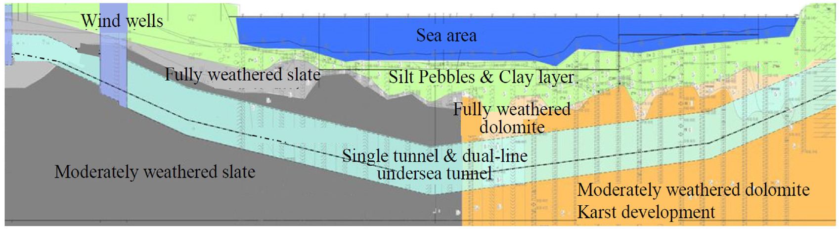
The geology of the subsea tunnel is extremely complex and there is a huge amount of corresponding data. Moreover, there are many repetitive geological feature data. Thus, an accessible practice is to select the geology of the middle part of the whole tunnel route to carry out research, as its diversity can basically cover the whole project. The representative geology is that of the 120-ring segment interval (about 240 m long) from ring 565 to ring 685, which can be considered a typical section for the main bearing load analysis. The vertical section of the geological distribution and its segment layout are illustrated in Figure 6.

The longitudinal view of the tunnel.
Data acquisition scheme
Aiming at the previously mentioned representative engineering geology, a data acquisition scheme was formulated. More precisely, the dynamic tunneling data stored in the device for nearly 2 months from February 3, 2020 to March 25, 2020 were collected. The data parameters of the original document comprise more than 1400 items, which reflect both the working conditions and the overall operation results. Among these items, 38 are directly related to the calculation of the main bearing loads, and the extracted characteristic data are summarized in Table 1.
The classification of the feature data.

Data processing and results analysis
Data reduction and cleaning processing were performed for the dynamic parameters of the equipment. More precisely, the data of some abnormal positions were filtered. The dynamic characteristic parameters were analyzed as the load inputs. The curves of the cylinder pressure changes, cylinder push rod displacement changes, and motor torque changes in the 120-ring section were then obtained, as shown in Figures 7 to 9, respectively. The analysis reveals the following.
(1) The rod cavity pressures of the hydraulic cylinders in each group were almost synchronous, mainly varying in the range of 100–160 bar. In addition, the pressures in the rodless cavity of the cylinders in groups A and B were much smaller, varying between 5 and 50 bar and 5 and 20 bar, respectively. The pressure in the rodless cavity of the cylinders in group C was almost 150 bar, which indicates that there were great differences in the push rod force of the main drive groups.
(2) The displacements of the hydraulic cylinders in groups A, B, and C varied between 145 and 151 mm, while the displacement variation of each group was not synchronous. The displacement relationship was SC > SB > SA for rings 565–612, and that for rings 612–685 was SA > SC > SB. This reflects the change of the attitude of the main drive system.
(3) The torques of each driving motor varied approximately synchronously, except for that of motor #12, which had a variation range of 120–320 kN/m. This indicates that all the motors cannot be completely synchronized under such geological conditions.
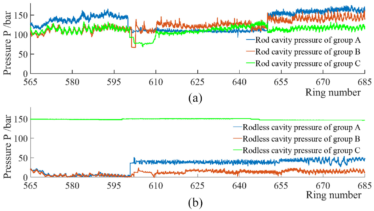
The pressure changes of the cylinders with rod and rodless cavities in the 120-ring segment interval: (a) pressure changes of rod cavity and (b) pressure changes of rodless cavity.

The displacement changes of the cylinder rods in the 120-ring segment interval.

The motor torque changes in each group.
Based on the proposed characteristic load inputs and the relationships between the previously derived load indexes of the main bearing and the dynamic characteristic parameters, the changes of the load indexes were then obtained through programming, as shown in Figure 10.

The changes of the load indexes of the main bearing in the 120-ring segment interval.
After comparing the load indexes with the geological conditions, the following can be concluded.
(1) In the 120-ring segment tunneling interval, the strata of the moderately weathered dolomitic limestone and filling karst cave in rings 595–670 had fairly large corresponding loads, accounting for almost 60% of the study time. Particularly, the axial force Fa changed around 2.1 × 10⁴ kN, the radial force Fr changed around 0.7 × 10⁴ kN, the overturning moment Mk changed around 4.8 × 10³ kNm, and the torque T changed around 3.5 × 10³ kNm.
(2) The corresponding loads fluctuated greatly in the diabase formation of rings 565–595. More specifically, the axial force Fa varied in the range of (1.1–1.4) × 104 kN, the radial force Fr changed around 0.7 × 10⁴ kN, the overturning moment Mk varied in the range of (4.2–5.0)× 103 kNm, and the torque T varied in the range of (0.7–1.8) × 103 kNm.
(3) The load levels corresponding to different geologies were considerably different. The loads under the dolomitic limestone and filling karst cave strata were almost 1.5–1.9 times greater than that under the diabase stratum, and the torque was almost five times greater.
Conclusion
Based on the typical telescopic swing main drive system, the dynamic characteristic parameters during construction, and complex geological conditions, the load characterization of a large main bearing was investigated. The following conclusions can be drawn.
(1) The mechanical model of the main drive system was developed to express the changing attitude. On this basis, the axial force Fa, radial force Fr, overturning moment Mk, torque T, and characteristic parameters of the cylinders (displacements SA, SB, and SC, cylinder rod cavity pressures PbA, PbB, and PbC, rodless cavity pressures PrA, PrB, and PrC, and torques Ti (i = 1, 2, …, 12) of the driving motors), were used to represent the main bearing load indexes. The main bearing loads are reflected by the changes of the dynamic characteristic parameters.
(2) The actual load conditions of the main bearing were characterized in terms of the changes of the dynamic characteristic parameters. Different geologies corresponded to different load levels. The load under the dolomitic limestone and filling karst cave strata was almost 1.5–1.9 times greater than that under the diabase stratum, and the torque was almost five times greater. The load level values of the main bearing under typical geological conditions provide an accurate and reasonable load input condition for the design and selection of the main bearing.
Footnotes
Appendix
Handling Editor: Chenhui Liang
Declaration of conflicting interests
The author(s) declared no potential conflicts of interest with respect to the research, authorship, and/or publication of this article.
Funding
The author(s) disclosed receipt of the following financial support for the research, authorship, and/or publication of this article: This work was supported by the National Key Research and Development Program of China (Grant No. 2020YFB2006800).