
Abstract
At present, the vibrational coupling mechanism of the rotor system with a double-disk magnetic coupler has not been sufficiently studied. Based on the mechanical impedance theory, the patterns of structural mass and stiffness distribution were quantitatively described, to establish the model for the vibrational coupling mechanism. Methods were proposed to determine the vibrational coupling point and to simulate the transient response to the interacting excitations, so as to analyze the potential vibrational coupling point and the dynamic response characteristics. Then, the Campbell diagram of the shared support-dual rotor system was combined with the mechanical impedance characteristics of the shared support. As a result, it was found that although the base vibration of the shared support was significantly amplified, the single-axis trajectory showed that both the output and input rotors were synchronized with the forward vortex motion, with almost no coupling between them. A double-disk magnetic coupler test bench with a rated power of 55 kW was designed to verify the experiments. The results showed that the vibration displacement occurred in a periodic variation pattern. Moreover, the maximum errors between the theoretical, simulated, and experimental values of the vibration displacement at different input speeds were less than 5%. The experiments verified the validity of the model for the vibrational coupling mechanism and the simulation of the transient response to the interacting excitation. The results of the study could be used as a basis for calculating the vibration of the rotor system with a double-disk magnetic coupler.
Keywords
Introduction
With its advantages of high transmission efficiency, low carbon emission, and low energy consumption, the magnetic coupler has become one of the most investigated transmission devices for coal mining machinery.1,2 The double-disk magnetic coupler has the advantages of high torque density and high efficiency, so it gradually evolves as a mechanical flexible transmission device.3,4 The output and input rotors of the double-disk magnetic coupler are both supported by a shared bearing frame, forming a rotor system with a double-disk magnetic coupler. The unique structure plus the interacting excitation load of the dual rotors can easily result in complex coupling vibration characteristics of the structural system, making it difficult for the dynamic design.5–8 Therefore, it is of great research value and engineering significance to explore the vibrational coupling mechanism and characteristics of the rotor system with a double-disk magnetic coupler.9–11
At present, many studies have been conducted worldwide on the vibrational coupling of the rotor system. Yunfan et al. 12 established a dual-rotor dynamics model, where the effects of the intermediary bearing stiffness and the gyroscopic moment of high- and low-pressure rotors were introduced. This revealed the differences in the critical speed characteristic and unbalanced response in a dual-rotor system, as well as the effects of the speed ratio on them. Zhaojun et al. 13 addressed the effect of the air gap magnetic field on the system with an inhomogeneous air gap during the vibration eccentricity of a three-phase AC rotor. They investigated the coupling mechanism of parametrically excited vibration and forced vibration in the system and analyzed the conditions for the strong resonance of the system. Qingzhong et al. 14 analyzed the causes of vibration in a hybrid permanent magnet eddy current coupler and employed simulation software to simulate the conductor rotor, permanent magnet rotor, and housing. By optimizing the structure, they managed to suppress the vibration, improved the service life, and reduced the equipment failure rate. Huashan et al. 15 conducted numerical simulations of the internal flow field of the hydraulic coupler pump wheel under axial vibration conditions to analyze the two-phase flow patterns and force characteristics inside the flow channel of the hydraulic coupler. Zhiqiang and Yunhe16–18 proposed that the stator rotor friction induced by electromechanical coupling oscillation of the shaft system of a hydraulic turbine would aggravate the bending-torsion coupling vibration of the rotor system and that a coupling relationship could be established between the transverse and longitudinal dynamic characteristics of the shaft system through the thrust bearing. 18 Yoo et al. 19 demonstrate a vibration test for a resonant MEMS scanning system in operation to evaluate the vibration immunity for automotive lidar applications. An analysis of energy variation is proposed, showing direction dependency of vibration coupling. Yang et al. 20 propose an analytical method based on the mode superposition and Galerkin hybrid method (MSGHM) has been proposed for vehicle-SFT-current coupling vibration, the influences of several structural parameters on the vehicle-SFT-current coupling vibration are discussed. Magdy et al. 21 discusses intensively the dynamic characteristics of a cantilever composite wing with both torsion and bending coupling to represent both material and geometric coupling, a MATLAB code is developed and results are validated in comparison with published work. Such a comparison shows a good agreement between both results. Guo and Bai 22 use a test rig of a motor whose rotor supported by ball bearings and present a two-degrees of freedom magnetic solid coupling dynamic model of the motor rotor system. The nonlinear dynamic response and spectrum are obtained from experiments and numerical analysis. The numerical results are in good agreement with test data, thus validating the presented model. Boesing et al. 23 presented a mathematical model for studying the dynamic properties of rotor-bearing-coupling system under the effects of varying compliance, radial clearance, rotor-stator rubbing, raceway defects, and surface waviness. The effects of typical parameters on mechanical characteristics and nonlinear dynamic response of the rotor system are analyzed by means of bifurcation diagrams, speed-amplitude, time-histories, spectrum, phase diagrams, and Poincaré sections. However, there have been few studies on the vibrational coupling mechanism of rotor systems with double-disk magnetic couplers, which led to a limited understanding of the vibration event and its rapid troubleshooting.
In this paper, focusing on the rotor system with a double-disk magnetic coupler, its structural characteristics and different types of vibrational coupling mechanical processes were analyzed. Based on the mechanical impedance theory, the vibrational coupling mechanism model was established, and the vibrational coupling point and the vibration displacement were determined by simulating the transient response to the interacting excitation. Finally, experimental verification was carried out on a double-disk magnetic coupler test bench with a rated power of 55 kW.
Vibrational coupling mechanism of rotor system with double-disk magnetic coupler
Structural characteristics
Figure 1 shows the structural sketch of the rotor system with a double-disk magnetic coupler. The output rotor is a quasi-rigid rotor with a 1-1-0 support scheme, while the input rotor is a frame structure with a 0-1-1 support scheme. Both have one pivot point at the left copper disk and one at the right copper disk. The output and input rotors are simultaneously supported by a shared bearing frame, forming a rotor system with a double-disk magnetic coupler. The two rotors operate in different speed ranges and cover a wide frequency range. Moreover, due to the lightweight design requirements, the modal frequency of the shared support structure falls in a wide range, which is not easy to avoid “resonance.” This brings a more complex problem of vibrational coupling suppression between the rotor system and the support structure.

Structural sketch of the rotor system with double-disk magnetic coupler.
Mechanical processes of vibrational coupling in the rotor system
For systems with a shared frame-rotor structure, under the action of mechanical-electromagnetic and other operating loads, the vibrational response of the shared support structure will produce base excitation to the rotor system. Under certain circumstances, vibrational coupling of the system can be induced, and the coupling state is related to the base vibration frequency and amplitude of the shared support. There are two major types of vibrational coupling: (1) the vibrational coupling under the base excitation of the shared support; (2) the vibrational coupling under the interacting excitation between rotors.
When the rotor (the input or output rotor) passes through a critical speed of its own, or when the rotor (the input or output rotor) has the same modal frequency of the shared frame, the shared support will generate a high forced vibration response, affecting the motion state of both input and output rotors, causing vibrational coupling of the structural system. The mechanical nature of such a problem is that the shared support generates a base vibration with a large amplitude, and the degree of vibrational coupling is related to the mechanical impedance characteristics of the shared support.
The rotor system with a double-disk magnetic coupler employs a shared support, where the dynamic load excitation at the pivot point of the input rotor can be applied to the pivot point of the output rotor through the base vibration of the shared support, thereby producing excitation to the output rotor. When the excitation frequency of the input rotor is close to the modal frequency of the output rotor, the excited rotor (i.e., the output rotor) is in a resonant state. However, since the excited rotor speed differs from the feed frequency, both the input and output rotors are in uncoordinated eddy motion. Alternating loads are generated within the output shaft, which may cause instability in the input or output rotor or high cycle fatigue fracture in the output shaft.
Vibrational coupling mechanism model
Based on the structural characteristics of the rotor system with a double-disk magnetic coupler, a vibrational coupling mechanism model was established as shown in Figure 2. Here, only the rotor system motion in the x-direction was considered, and the motion in the z-direction and angular motion in θ-direction of the shared support were taken into account. The rotor shaft of the rotor system was a rigid beam without mass. As shown in Figure 2, x1, x2, and x3 are the x-direction displacement of the input rotor, the output rotor, and the shared support, respectively; θ is the angular movement of the shared support; k1, k2, k3, k4 are the stiffnesses of the pivot points, respectively; k5 and kθ are the equivalent radials and angular stiffnesses of the shared support; m1, m2, and m3 are the equivalent masses of the input rotor, the output rotor, and the shared support, respectively; Jf is the equivalent rotational inertia of the shared support; w1 is the rotational angular velocities of the input rotors, and w2 is the rotational angular velocities of the output rotors; and e is the mass offset of the output rotor; l1 and l2 are the axial distances between the pivot points of the input and output rotors on the left and the equivalent mass center of the shared support.

Model for the vibrational coupling mechanism of the rotor system with double-disk magnetic coupler.
Considering only the unbalance excitation of the output rotor, the generalized impedance equation for the mechanics model of the rotor system can be written as

Z, X, and F are the impedance matrix, vibration amplitude vector, and force amplitude vector of the rotor system with a double-disk magnetic coupler, respectively. The terms in the equation are in the following order:

X 1, X2, and X3 are the amplitudes of the input rotor, the output rotor, and the shared support in each degree of freedom, respectively; Θ3 is the amplitude of the shared support in the angular degree of freedom. Zij is the impedance element, which is expressed as


In the rotor system with a double-disk magnetic coupler, the input and output rotors are coupled to the radial and angular degrees of freedom of the shared support through the cross-impedance term, respectively. When the dynamic loads at the pivot points of the input or output rotor are applied to the shared support, the vibrational response, which in turn acts as the base excitation, is induced and affects the motion state of the rotor system. Therefore, the mechanical nature of the vibrational coupling in the rotor system with a double-disk magnetic coupler is the coupling under dynamic response to the interactions between the unbalance excitation of the input/output rotor and the base vibration excitation of the support structure. The degree of coupling between the rotor systems is related to the mechanical impedance characteristics of the shared support.
Determining the vibrational coupling point of the double-disk magnetic coupler
Finite element modeling and analysis method
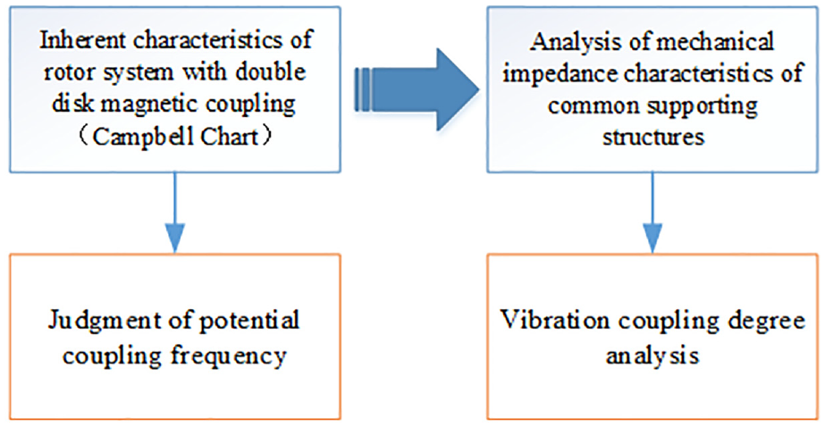
Based on the simulation analysis of the inherent characteristics and the mechanical impedance characteristics in the rotor system with a double-disk magnetic coupler, the system can determine and evaluate the potential vibrational coupling points, and the analysis process is shown in Figure 3.
Determining the vibrational coupling points in the rotor system with a double-disk magnetic coupler.
The finite element model of the rotor system with a double-disk magnetic coupler is shown in Figure 4. The bearing and elastic support structure in the system are simulated by the spring unit and reasonably simplified. Combined with the working principle of the double-disk magnetic coupler, the spring units at the first and second pivot points of the input rotor are circumferentially constrained at the outer end. A circumferential constraint is applied to the outer end of the spring unit at the third pivot point of the output rotor. The fourth pivot point is supported by the shared support, and the spring unit is used to connect the corresponding nodes of the rotor/stator and to couple the nodes with circumferential displacement.

Rotor system with double-disk magnetic coupler finite element model.
The ANSYS inherent mode solver module was used to analyze the inherent characteristics of the rotor system with a double-disk magnetic coupler. Considering the relationship of the common working speed between input and output rotors, as well as the gyroscopic moment effect, the variation curves of the eigenvalues of the modal positive progression of the input rotor, the output rotor, and the shared support with the input speed were obtained.
The ANSYS transient dynamic analysis module was used to analyze the response characteristics of the rotor system with a double-disk magnetic coupler. The transient dynamic response at the potential vibrational coupling points was calculated by applying 50 g/mm of unbalance (with reference to the actual balance accuracy) to the rims of the input and output rotors, and the steady state section of the response was obtained for analysis.
Inherent vibration characteristics of the rotor system with double-disk magnetic coupler
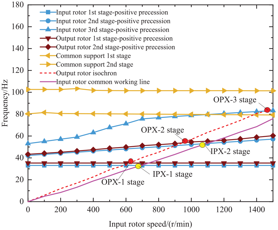
Figure 5 shows the Campbell diagram of the rotor system with a double-disk magnetic coupler. The horizontal coordinate is the input rotor speed. However, it is different from the single-rotor system. In addition to the isochronous speed line of the output rotor and the resonant frequency line at various orders (brown line in the figure), the shared working line of the input rotor system and the vibration frequency line at various orders (blue line in the figure) are added to take into account the vibration characteristics of the input rotor; the resonant frequency line (yellow line in the figure) was added to take into account the structural resonance characteristics of the shared support.
The Campbell diagram of rotor system.
The intersection of the speed line and the resonant frequency line, combined with the modal vibration pattern, allows a quick determination of the potential vibrational coupling frequency. The intersection of the speed line of the output rotor and the vibration-dominated resonant frequency line of the output rotor denotes the critical speed of the output rotor. The intersection of the isochronous speed line of the output rotor and the resonant frequency line of the shared support (at the first and second orders) denotes the vibrational coupling frequency of the potential base excitation. The intersection of the isochronous speed line of the output rotor and the modal frequency line of the input rotor denotes the vibrational coupling point of the interacting excitations between rotors induced by the potential output rotor. A similar method is used for the input rotor.
In Figure 5, OPX-i and IPX-i represent the potential resonance points excited by the output and input rotors, respectively, indicating the critical speed point and the shared support when i = first order, second order, third order, …. The speed range of the output rotor is 0–1444 r/min, and that of the input rotor is 0–1500 r/min.
The results show that within the analyzed speed range, the output rotor has third-order critical speed, while the input rotor has second-order critical speed. The above critical speeds are both within the operating speed range. This indicates that this vibration pattern is prone to generate great dynamic loads at the pivot points. As a result, the vibration response of the shared support can be large, which may cause vibrational coupling of base excitation of the shared support. It can be preliminarily determined that for the rotor system with a double-disk magnetic coupler, the vibrational coupling frequency points of the potential base excitation within the operating speed range are OPX-1st order, OPX-2nd order, IPX-1st order, and IPX-2nd order, and the vibrational coupling point of the interacting excitation between rotors is OPX-3rd order. The speed characteristics at the vibrational coupling points are shown in Table 1, and the corresponding modal vibration patterns are shown in Figure 6.
Speeds at the potential vibrational coupling points of the rotor system with a double-disk magnetic coupler.


Modal vibration patterns at the potential vibrational coupling points of the rotor system with double-disk magnetic coupler: (a) OPX-1st mode shape, (b) OPX-2nd mode shape, (c) IPX-1st mode shape, (d) IPX-2nd mode shape, and (e) OPX-3rd mode shape.
Mechanical impedance characteristics of the shared support
The intersection of the speed line and the modal frequency line is only necessary for the occurrence of vibrational coupling. Further analysis of the mechanical impedance characteristics of the shared support can determine the possibilities of vibrational coupling at each potential frequency point. The dynamic stiffness of the shared support reflects its resistance to the dynamic loads at the pivot points, which affects the base vibration amplitude and the vibrational coupling between rotors. The expressions are defined as:

where Zi(ω) is the dynamic stiffness of the ith pivot point, Fi(ω) is the dynamic load amplitude of ith pivot point, and Xi(ω) is the displacement amplitude of ith pivot point.
Figure 7 shows the dynamic stiffness and displacement transfer rate at the pivot points of the shared support structure. The effects of the squeeze film damper on the dynamic stiffness and displacement transfer rate at the pivot points are not considered in the analysis. The damping of the shared support is simply considered by setting the overall damping ratio of the structure in ANSYS.

Dynamic stiffness of the shared support.
As suggested by Figure 7, the dynamic stiffness of the shared support is high at OPX-1st order and OPX-3rd order, where vibrational coupling cannot easily occur between the input and output rotors. However, the resonance of the shared support occurs at the OPX-2nd order point, and stiffness suddenly decreases at the fourth pivot point, which may cause vibrational coupling under the base excitation of the shared support.
Response characteristics at vibrational coupling points in structural system with double-disk magnetic coupler
Based on the potential vibrational coupling points determined above, it is known that OPX-2nd order is both the vibrational coupling point of the potential base excitation and the vibrational coupling point of the interacting excitation between rotors. Therefore, its response characteristics were calculated and analyzed.
To quantitatively describe the degree of vibrational coupling between the input and output rotors of a double-disk magnetic coupler, the dynamic response coupling factor at the fourth pivot point is defined.
The factor of dynamic coupling from the output rotor to the input rotor the fourth pivot point ϕ4 is

where A4ωo is the frequency response amplitude of the output rotor at the fourth pivot point, A4ωi is the frequency response amplitude of the input rotor at the fourth pivot point.
The dynamic response under resonance (OPX-2nd order) of the shared support structure is calculated, and the elastic lines are plotted as shown in Figure 8. The shaft centerline orbits of the input rotor, the output rotor, and the shared support at the fourth pivot point is plotted as shown in Figure 9.

Elastic line of the shared support (OPX-2nd order).

Shaft centerline orbit of the pivot points: (a)Track diagram of common support and output rotor at No. 4 fulcrum (b)Track diagram of common support and input rotor at No. 4 fulcrum.
According to Figure 8, during the resonance of the shared support, the displacement transfer rate between the third and fourth pivot points was about 2.9, and the base vibration of the shared support was significantly amplified at the fourth pivot point. The shaft centerline orbit in Figure 9 shows that both the output and input rotors were synchronized with the forward vortex motion. Although the deformation of the input rotor was greater than that of the output rotor, the displacements of the two were basically the same at the fourth pivot point. The frequency response at the fourth pivot point in Figure 10 shows that the frequency response amplitude A4ωi of the input rotor was greater than the frequency response amplitude A4ωo of the output rotor. The input and output rotors were almost not coupled, and the dynamic coupling factor between them was approximately 0. In summary, during the resonance of the shared support, vibrational coupling of the rotor system with a double-disk magnetic coupler did not occur under base excitation.

Frequency response at the fourth pivot point.
Experiments
Experimental design
In order to verify the validity of the above vibration model, a test bench prototype with a double-disk magnetic coupler was analyzed, with parameters shown in Table 1 and the experimental diagram shown in Figure 11. The main components included MCC1608G data acquisition card (range of ±10 V analog output), CT5201 constant current adaptor, and CT1010LC vibration acceleration sensor (sensitivity of 103.6 mV/g). Limited by the installation conditions and the test costs of the double-disk magnetic coupler, it was impossible to arrange the sensor on the high-speed rotating permanent magnet rotor to measure its vibration acceleration directly. The vibration of the double-disk magnetic coupler would cause the longitudinal vibration of the output shaft sleeve via the permanent magnet rotor. Therefore, the longitudinal vibration signal of the output shaft sleeve was measured by arranging acceleration sensors at the sleeve, so as to indirectly capture the vibration. 24
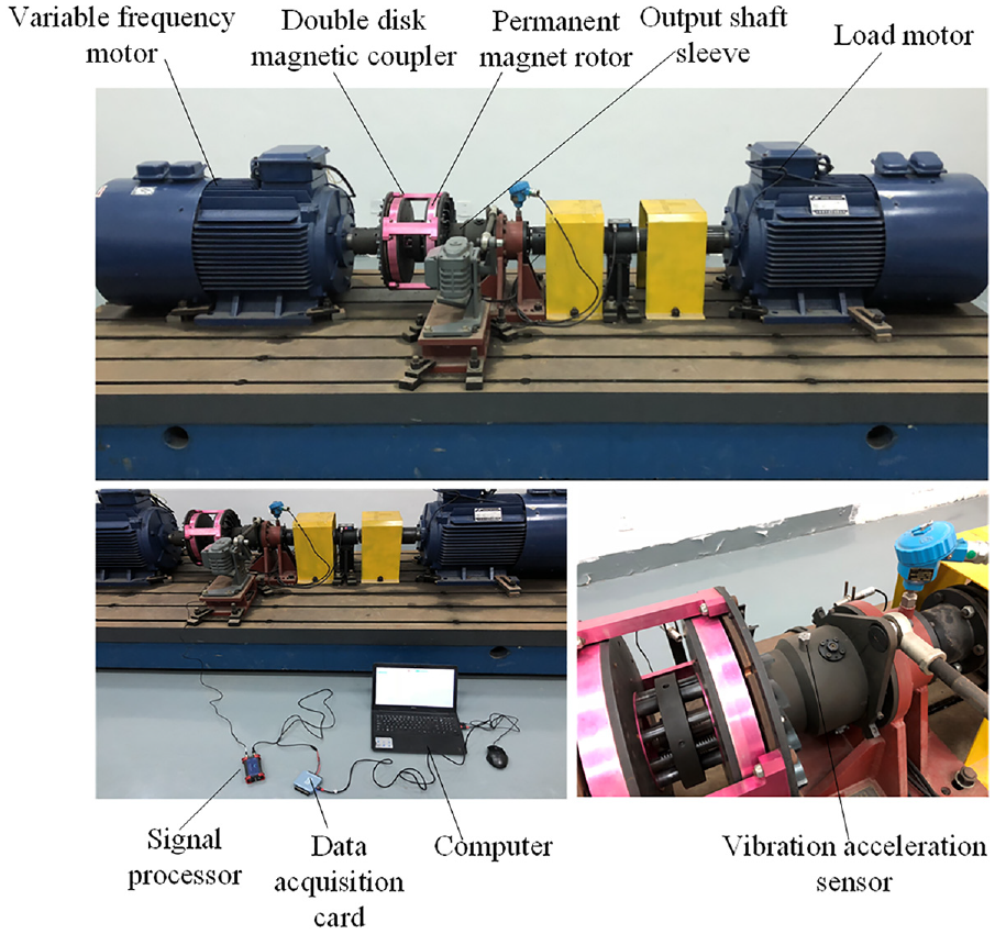
Experimental diagram of the double-disk magnetic coupler.
Comparison of theoretical, simulated, and experimental results of the vibration displacement
Experimental approach
In the experiment, after the inverter motor was started, the load torque was first set to 200 N/m. The air gap between the permanent magnet rotor and the copper disks was kept constant by outputting commands from the console, and the speed of the inverter motor (the input motor) was gradually adjusted to provide a speed of 0–1500 r/min.
Signal and data processing
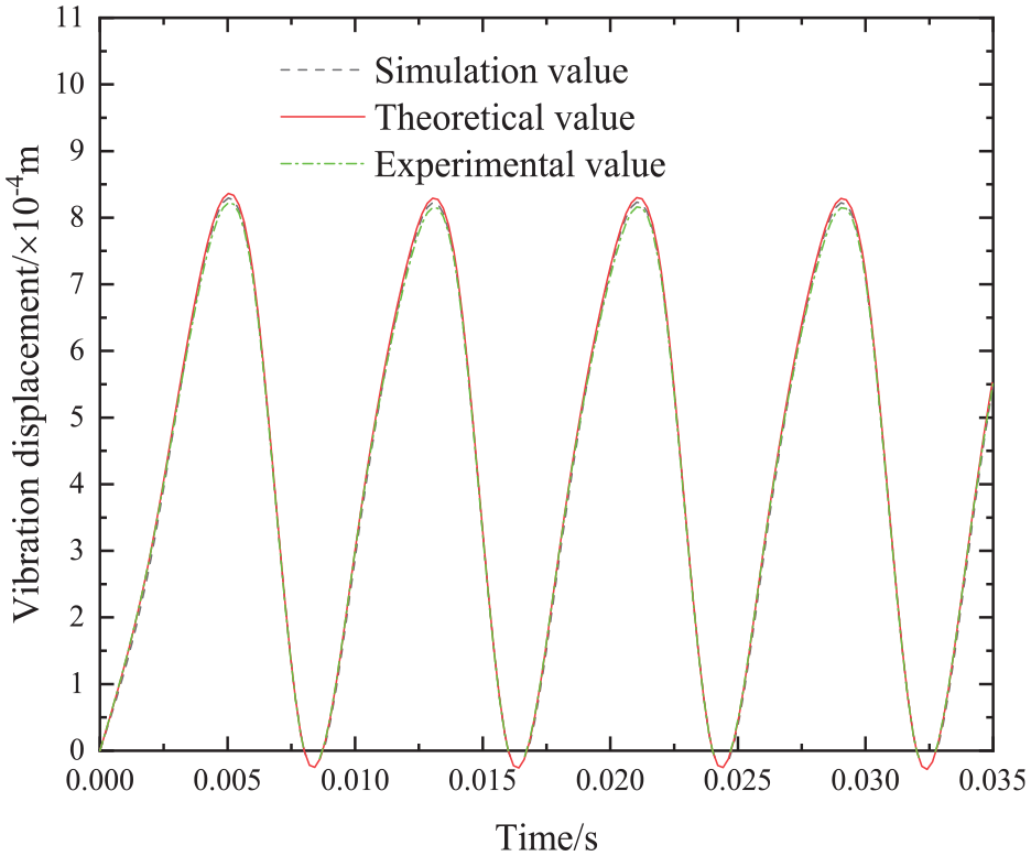
The acceleration amplitude data of the double-disk magnetic coupler at different input speeds were obtained by the vibration acquisition system. The resulting vibration acceleration waveform was integrated twice to obtain the vibration displacement waveform at the fourth pivot point. Figure 12 shows the comparison of the theoretical, simulated, and experimental values of the vibration displacement at the fourth pivot point of the double-disk magnetic coupler at a speed of 1500 r/min.
Comparison of the theoretical, simulated, and experimental values of the vibration displacement.
According to Figure 12, the vibration displacement at the fourth pivot point shows a periodic variation pattern, and the theoretical and simulated values of the vibration displacement are in good agreement with the experimental value. When the input speed was changed to 900, 1200, and 1500 r/min, the theoretical, simulated, and experimental values of the vibration displacement amplitude at the fourth pivot point were compared as shown in Table 2. As suggested by Table 2, the vibration displacement in the model for the rotor system with a double-disk magnetic coupler was accurate, with the maximum errors in the theoretical, simulated, and experimental values all less than 5%. The model could be used to simulate the vibration displacement at different input speeds.
Comparison of the theoretical, simulated, and experimental values of the displacement amplitude at the fourth pivot point at different input speeds.

Conclusions
For the rotor system with a double-disk magnetic coupler, the structural characteristics and the mechanical processes of different types of vibrational coupling were analyzed. The model for the vibrational coupling mechanism was established on the basis of the mechanical impedance theory. A simulation method was used to analyze the potential vibrational coupling points and the dynamic response characteristics of the structural system based on the inherent characteristics and the transient response to the interacting excitation of the input rotor, the output rotor, and the shared support. Experiments were designed to validate the model and simulation, and the following conclusions were drawn:
During resonance at the OPX-2nd order point of the shared support, although the base vibration at the fourth pivot point was significantly amplified, the shaft centerline orbit showed that both the output and input rotors were synchronized with the forward vortex motion. The input and output rotors were almost not coupled, and the dynamic coupling factor between them was approximately 0. That is, there was no vibrational coupling under base excitation in the rotor system with a double-disk magnetic coupler.
A double-disk magnetic coupler test bench was built to verify the vibrational coupling mechanism model and simulation method. The results showed that the vibration displacement occurred in a periodic variation pattern at the fourth pivot point. The maximum errors in the theoretical, simulated, and experimental values of the vibration displacement were all less than 5%. The model could be used to calculate the design of vibration reduction measures for actual double-disk magnetic couplers.
Footnotes
Handling Editor: Chenhui Liang
Declaration of conflicting interests
The author(s) declared no potential conflicts of interest with respect to the research, authorship, and/or publication of this article.
Funding
The author(s) disclosed receipt of the following financial support for the research, authorship, and/or publication of this article: We would like to express our appreciation to National Natural Science Foundation of China (52274152), Outstanding Youth Scientific Research Project of Anhui University (2022AH020056),The University Synergy Innovation Program of Anhui Province (GXXT-2020-60 and GXXT-2022-16), Open Fund of the State Key Laboratory for Mining Response and Disaster Prevention and Control of Deep Coal Mines (SKLMRDPC20KF10).