
Abstract
Due to rapid development in the industry, operating speeds and eccentricity produced undesirable vibrations which may lead to damage in bearings, seals, and lubrication systems. In the proposed paper, a novel analytical method was presented using an integrated multi-body dynamics and finite element analysis to simulate the lateral and torsional vibration. This method was applied to a proposed model of single rotor-system. In order to study the lateral and torsional vibration of the system profoundly, three markers were placed on the locations of the left and right bearings and the mass center of the shaft. The effects of bearing force caused by lateral and torsional vibrations were also analyzed. The results showed that the lateral vibration has a great effect on the dynamic of single rotor-system when lowering motor speed. It was found that, as motor speed increased, the motion of the system becomes more stable with steady fluctuates of the displacement response. The calculated natural frequency of SRS is compared with theoretical results to verify the transient solver. This novel method is practical in analyzing the lateral and torsional vibration of the SRS under various speeds and eccentricities.
Keywords
Introduction
Due to the rapid development in industry, rotor-bearing systems such as motors, jet engines, pumps, turbines, and auto engines usually subject to high speed in order to achieve a high productivity request. In high-speed rotor-bearing systems, the unbalance and eccentricity which produced by manufacturing errors cause undesirable vibrations. The most dangerous of these vibrations are excessive lateral and torsional vibrations, which can lead to damage in bearings, seals, lubrication systems and therefore lead to a complete failure of the rotating machinery 1 ; and therefore, affect the normal operation of the rotor-system.2–4 In order to make these systems work with normal operation, efficient and safety, many scholars have completed analytical and numerical analysis for studying lateral and torsional vibrations with excited parameters such as unbalance, fatigue, crack, and eccentricity. Cohen and Porat 5 investigated the effect of combination resonance in coupled torsional and transverse vibration using an unbalanced rotor model; the model is driven by a torsion flexible shaft under a constant velocity joint condition. Bernasconi 6 presented analytical and experimental study on the longitudinal component of the angular momentum produced by torsional vibrations through a frequency of double rotation frequency. Nataraj 7 concluded that the interaction between torsion and transverse vibration happened at second order. Mohiuddin and Khulief 8 established the finite element formulation to study the coupled bending and torsional motions of elastodynamic model of the rotating shaft using the Lagrangian approach. In their study, the gyroscopic effects and the inertia coupling between bending and torsional deformations were taken into consideration. Niu and Yang 9 studied the behavior of fatigue degradation as a result of lateral vibration subjected to a cracked rotor by using fracture mechanics and dynamic theory. Considering unbalance eccentricity, behavior of fatigue degradation investigated numerically. Zhang et al. 10 used Runge-Kutta method and Reynolds’s equation in order to investigate the dynamic behavior of inner race defect in the rotor-bearing-SFD system. Peng et al. 11 Imposed mass eccentricity to the cracked Jeffcott rotor and studied the stability based upon the numerical Floquet method. Werner 12 derived a mathematical rotordynamics model to analysis the lateral vibration of induction motors in start-up period with regarding eccentricities. Sukkar and Yigit 13 analyzed a fully coupled lateral and torsional vibration of axial loaded unbalanced rotor, and a lumped parameter model presented based on lagrangian procedure. Lai 14 studied the lateral vibration of shaft generator system of hydro-turbine using FEM. Shen et al. 15 derived equations of motion of the coupled torsional-lateral vibration model with six degrees of freedom and using Lagrange approach and two kinds of unbalance. Yu et al. 16 derived equations of motion for the mechanical model of unbalanced Jeff coat rotor supported by roller bearings by using Lagrangian approach. Gosiewski 17 established a rotor dynamic model under case of unbalance that accounts both lateral displacement and torsional angle by using the Evans method. Al-Bedoor 18 presented coupled torsional and lateral vibrations of unbalanced rotors model to account the rubbing between rotor and stator. The equation of the system was derived based on Lagrangian and then analyzed numerically depending on algorithm. Li 19 developed a model to study the coupled lateral-torsional vibration of a rotor bearing-gear system nonlinearly. The calculation of time solutions was performed numerically. Hsieh 20 developed rotor-bearing system model for analyzing coupled lateral-torsional vibration with applied external torque based on transfer matrix method. Yuan et al. 21 established a dynamic model of a Jeffcott rotor using Lagrangian approach to analyze the harmonics of rotating speed frequencies. The system stability was analyzed by using both the harmonic balance method and Folquet theory.
The previous investigators have used different methods to analysis the lateral and torsional vibration; some of them have used an analytical method and the others have used numerical methods; however the analytical method based on combined integrated multi-body dynamics (MBD) and finite element analysis (FEA) have never been discussed or reported, according to the authors’ knowledge.
In the present work, a new analytical method is presented using an integrated MBD and FEA in order to simulate the lateral and torsional vibration. This method is applied to a proposed model of single rotor-system (SRS). The SRS is supported by two identical ball bearings and excited through both analytical DC motor speeds and different mounted eccentricities. Three markers which were not considered by the previous investigators are located on: left bearing, shaft CM, and right bearing. An Integrated MBD and FEA method are applied in a wide range of speed with consideration of different disk eccentricities. This proposed method can deeply simulate and analyze the lateral and torsional vibration as well as the other vibration characteristics of the SRS under different rotational speeds and eccentricities. The bearing force effect on lateral amplitudes of vibration is also discussed in the proposed work. The bearing forces are analyzed by using the time domain and fast Fourier transforms (FFT). The time domain and frequency domain characteristics are also studied.
Establishing the SRS model
Automatic Dynamic Analysis of Mechanical Systems (ADAMS) software is widely used in MBD and FEA for system simulation. ADAMS method gives the possibility of adding movement and analyzing the dynamic behavior of the multi-body system model and its components. The SRS supported by two identical SKF ball bearings and derived by DC motor is proposed. This system consisted of a flexible shaft, disk and DC motor, as shown in Figure 1. The shaft and the disk were first modeled as a rigid body using ADAMS-view. Then the shaft was converted to the flexible body using ADAMS/Auto-Flex. After meshing the shaft with solid element type, tetrahedral element shape and linear element order with straight edge shape, the shaft model consisted of 1957 nodes and 586 elements as shown in Figure 2. Three markers were placed on the locations of the left and right bearings and the shaft CM as sown in Figure 1; in order to study the lateral and torsional vibration. The constraints and kinematic pairs that were used to connect each part are shown in Figure 3.

The proposed model of SRS.

The shaft mesh.
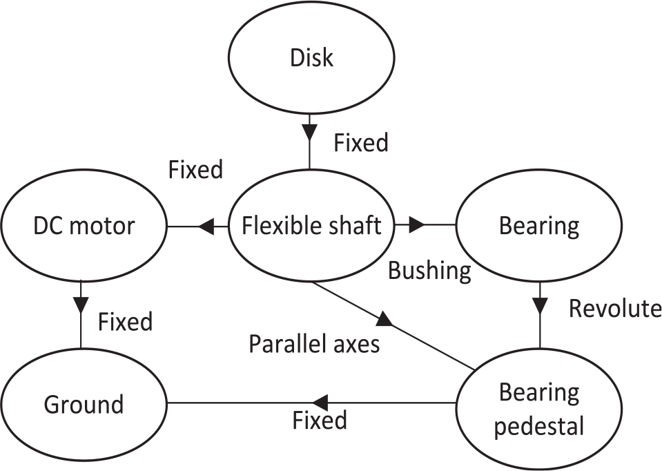
The constraint of each body in SRS model.
MBD and FEA approaches
In integration between the MBD and FEA software environments, the MBD analysis returns the state of motion and loads of the mechanical system; while FEA gives the flexibility state of the components. The fundamental approach engaged by Adams uses Lagrange’s formulation of the second form is obtained by the following equations 22 :


Where: q is the generalized coordinate, F is the equilibrium equation in the direction of generalized coordinate q, L is the Lagrangian (T-V), T is kinetic energy; V is potential energy, Φ is algebraic constraint equations, λ is Lagrange multiplier, Q is generalized Force, n is of generalized coordinates, m is of constraint equations (<or = n). The derivation of equations of motion of such as SRS was explained clearly by Yu 16 based on Lagrange’s equations.
Modeling of shunt DC motor
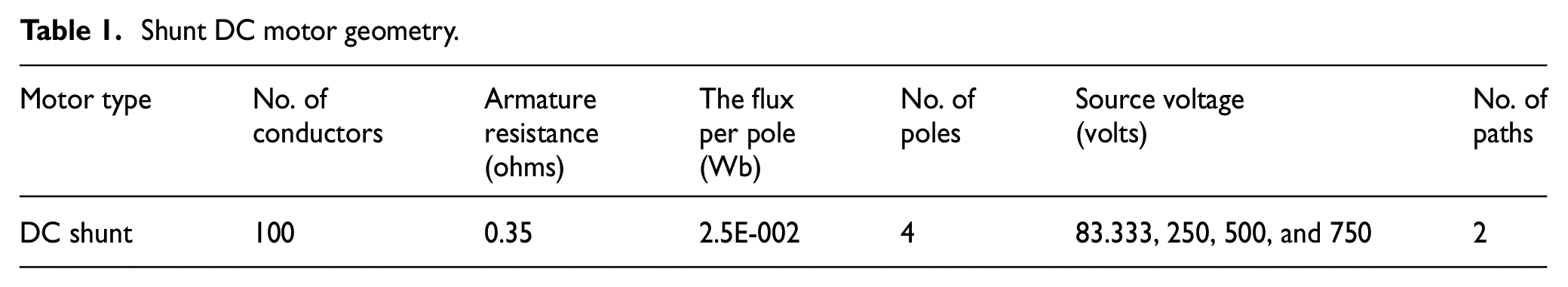
Using ADAMS/machinery, shunt DC motor was modeled based on the analytical method. This method is more flexible and allows editing the DC motor speed through controlling the change of the voltage applied to the armature. The specific geometry of the shunt DC motor used to derive SRS is listed in Table 1. In order to achieve the motor speeds of 1000, 3000, 6000, and 9000 rpm, the voltage applied to the armature was changed to 83.333, 250, 500, and 750 volts, respectively. Equations (4)–(7) controlled the speed of the motor.


Shunt DC motor geometry.
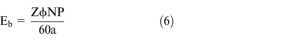
T is torque developed in N-m, K is torque constant, ϕ is flux per pole in Webers, Ia is armature current in Amperes, Z is Number of conductors, P is number of poles, a is number of parallel paths in the armature, Es is source voltage in Volts, Eb is back electromagnetic force induced in volts, Ra is armature resistance in Ohms, and N is revolutions per minute. Figure 4 shows the proposed model of SRS created by ADAMS.
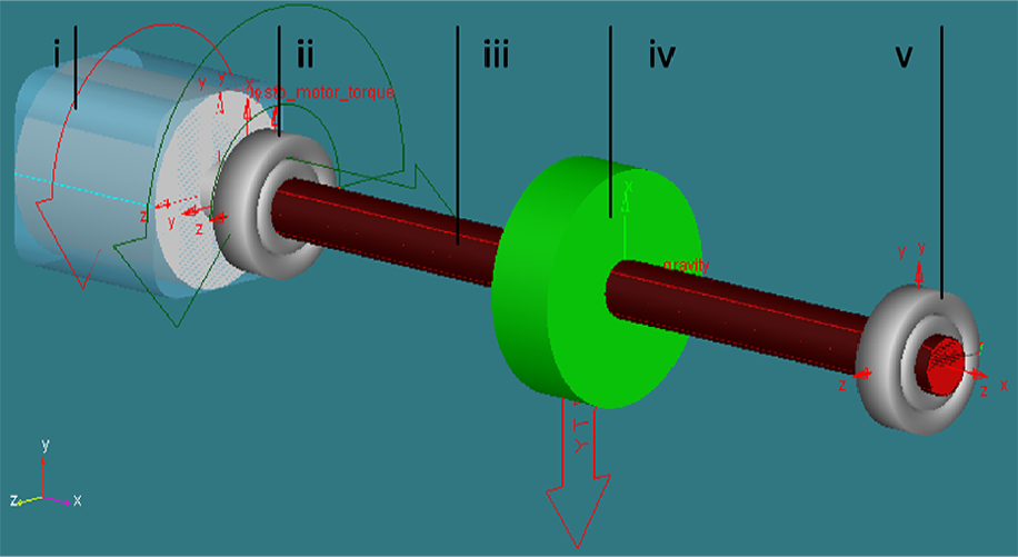
The proposed model of SRS created by ADAMS: (i) DC motor, (ii) left bearing, (iii) flexible shaft, (iv) rigid disk, and (v) right bearing.
Modeling of bearing
In order to support the SRS accurately and using ADAMS/machinery, single row deep groove ball bearing was modeled base on the detailed method with a body to ground type connection. This method is efficient and flexible; and allows selecting the values of characteristic geometry for many manufacturers’ catalog of bearings. It also provides a much accurate representation of bearing compliance. The Axial damping factor, radial damping factor, bending damping factor and torsional damping factor of the bearing are taken as 0.025 for the evaluation of the single row deep groove ball bearing. The damping coefficient is determined by multiplying the square root of the instantaneous stiffness by a user-entered damping factor. 23 The specific parameters of selected SKF single row deep groove ball bearing are shown in Table 2.
Parameters of SKF single row deep groove ball bearing.

Results and discussion
The simulation parameters of SRS supported by single row deep groove ball bearing are given as; material density of shaft is 7801 kg/m3, elastic modulus is 207 GPa, Poisson’s ratio is 0.29, the mass of shaft is 2.757 kg, the mass of disk is 3.5 kg, the eccentricity is taken as 0.1, 0.2, 0.3 mm, four motor speed of 1000, 3000, 6000, 9000 rpm are taken to excite the SRS. It should be noted that, in this work, the following assumptions were considered:
The type of the bearings and sizes which support the rotor are identical;
The gravity effect is considered;
For both bearings and the disk, the torsion angle are assumed to be zero;
The model of SRS runs at a time of 0.3 s and a step size of 0.001.
Effects of rotational speed on the lateral vibration of SRS
The change in motor speed has a direct effect on SRS vibration characteristics. 24 Figures 5–7 show the lateral vibration of the flexible shaft CM, left bearing and right bearing, respectively; varying with time. It can be seen that in motor speeds (1000, 3000, 6000, and 9000 rpm) with disk eccentricities (0.1, 0.2, and 0.3 mm), at low motor speed (1000 rpm), the waveform is chaotic in starting area near 0.0625 s and the lateral vibration has fluctuated unstably as shown in Figures 5(a)–7(a). This fluctuation is due to the starting up with flexible shaft and disk eccentricity. As the motor speed increases, the lateral vibration and the waveform become steadier. Despite the motor speed and the disk eccentricity increase especially in 3000, 6000, and 9000 rpm; the lateral vibration of SRS tends to be stable and presents a regular sine curve as shown in Figures 5(b–d)–7(b–d). As compare the parameters such as the bearing type, operation speed and rotor which assumed in this work and parameters assumed in the literature, This result can match with the simulation results that carried out by Liu et al. 25 ; which verifies a certain extent the accuracy of the current simulation. Besides, the predicted natural frequency and calculated natural frequency of SRS are compared in order to verify the accuracy of the solver, as shown in Table 3. The increased in the calculated natural frequency is due to eccentricity of the disk. 26 The vibration amplitude is smaller near the bearing because of the larger stiffness of the bearings. Therefore, it can be seen that the lateral vibration at flexible shaft CM is higher than the lateral vibration at both the left bearing marker and right bearing marker.

The lateral vibration of the flexible shaft CM with eccentricity 0.1 mm, 0.2 mm and 0.3 mm; when the motor speed: (a) 1000 rpm, (b) 3000 rpm, (c) 6000 rpm, and (d) 9000 rpm.

The lateral vibration of the left bearing with eccentricity 0.1 mm, 0.2 mm and 0.3 mm; when the motor speed: (a) 1000 rpm, (b) 3000 rpm, (c) 6000 rpm, and (d) 9000 rpm.

The lateral vibration of the right bearing with an eccentricity of 0.1 mm, 0.2 mm and 0.3 mm when the motor speed: (a) 1000 rpm, (b) 3000 rpm, (c) 6000 rpm, and (d) 9000 rpm.
SRS natural frequency compare.

In order to study the effect of motor speed on the dynamic characteristics of SRS, the displacement vibration amplitude of shaft CM, left and right bearing is extracted to analyze its vibration characteristics. Figure 8 shows the displacement vibration amplitude of flexible shaft CM varying with the motor speed at the axis of rotation x. The lines represent the maximum and minimum values of the displacement response of the system in the z-direction at different speeds and eccentricities. It is observed that because of the gravity influence on the rotor (flexible shaft CM), the shaft center is located in the lower vertical direction. 27 The speeds 6667, 8000, 8667, and 9000 rpm produced high amplitudes.

Displacement amplitude of shaft CM at different motor speeds and eccentricities.
The displacement vibration amplitude of the left and right bearings are shown in Figure 9. The displacement vibration amplitude is highest at the speed of 1850 and 9000 rpm, especially for the right bearing because of the effect of torsion. It can be seen that the gravity influence is less than of the shaft CM, besides as the amount of eccentricity increases, the amplitude of later vibration increases. It is better to reduce the influence of these high amplitudes bypassing these zones rapidly. It is also noticed that the displacement amplitude of left bearing is less than of the right bearing, which is due to the left bearing locating is near to the motor, which acts as additional support.

Displacement amplitude of left bearing and right at different motor speeds and eccentricities.
Effects of mounted eccentricity on lateral vibration and stability of SRS
Three different eccentricities of 0.1, 0.2, and 0.3 mm were mounted on the disk to study its effect on the lateral vibration of SRS. Zhou et al. 28 utilized the same amount of eccentricities to study the lateral vibration of the shaft in the pump-turbine system. The significant finding is that the amount of eccentricity has a great effect on the stability SRS. As shown in Figures 5–7; as the mounted eccentricity increases, the amplitude of later vibration increases and stability of the system is highest. 28
The effect of bearing force on SRS
The frequency-domain results of the left bearing marker and right bearing marker with different speeds and disk eccentricities illustrated in Figures 10 and 11. The bearing forces keep increasing as the mounted eccentricity increases. Besides that the bearing forces fluctuation increase gradually within a short period before settling on a steady oscillation pattern. From the frequency domain results, there is the main peak of the left bearing around 100 Hz and of right bearing around 150 Hz. The left bearing is much disturber than the right bearing due to high torque applied in the start-up. It can be seen that the frequency components are obviously visible in the eccentricity range of 0.1 to 0.3 mm and are no longer appear as the increase of eccentricity in both left and right bearing. It is not difficult to see that as the eccentricity increases the peak value also increases in the left and right bearing. In left bearing, the peak value equals 18.3464, 44.1401, and 73.7498 N for eccentricity equal 0.1, 0.2, and 0.3 mm, respectively. In right bearing, the peak value equals 126.8677, 247.0777, and 366.6304 N for eccentricity equal 0.1, 0.2, and 0.3 mm, respectively. This kind of peak values is mainly caused by the bearing reaction force between the inner and outer ring of the bearing and the roller.

The left bearing force and FFT.

The right bearing force and FFT.
The effect of torsional vibration on SRS
The rotational speed and angular displacement from the left tip of the flexible shaft during the start-up is shown in Figure 12. The start-up time for the system to reach the required speed is approximately small. The torsional vibration increases smoothly. This indicates that the operational speeds of the system go through a steady-state. The vibratory torque with respect to the rotational speed is shown in Figure 13. It shows that the torque is high in the beginning and then tends to zero at the end. This indicates that the system needs high torque to start-up and then gradually reaches zero.

The DC motor startup response.
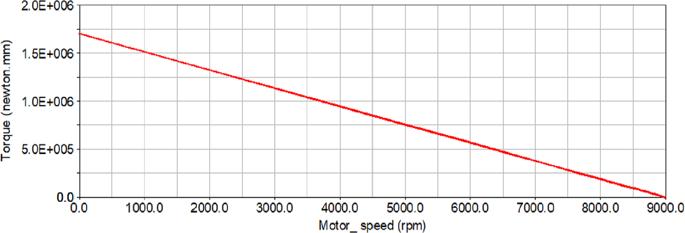
The motor torque–speed curve.
Conclusion
In present study, an integrated MBD and FEA method was proposed to study the lateral and torsional vibration responses for SRS. The SRS supported by single row deep groove ball bearing and excited by DC motor was established using ADAMS software. For the SRS, three markers were selected on the locations of the left and right bearings, and the shaft CM to study the effects of high speed and eccentricity on lateral vibration in details. The study was carried out under a different range of motor speeds and disk eccentricities. In additional, the effects of the bearing force produced by lateral vibration were investigated. The results carried out from the current study are summarized below:
When the operation speed of SRS is low (1000 rpm), the lateral vibration at the three markers has a great influence on the motion of SRS supported by the deep groove ball bearings, and it has a quiet influence on the displacement response. As the operation speed increases a particular interval, the motion is more stable, and the displacement response fluctuates more steadily.
Under low operation speed conditions, the lateral vibration of SRS is large in the start-up. With the gradual increase in the operational speed, the rotor system displacement response gradually becomes stable. Therefore, for the SRS supported by the deep groove ball bearing, it is better to pass the low-speed zone rapidly.
The vibration amplitude is smaller near the bearing because of the larger stiffness of the bearings. Therefore, it can be seen that the lateral vibration at flexible shaft CM is higher than the lateral vibration at both the left bearing marker and right bearing marker.
As the mounted eccentricities increase to a certain amount, the SRS tends to run steadily and stably.
As compared between left and right bearing, it is found that the displacement amplitude of left bearing is less than of the right bearing that is due to the left bearing is located near to the motor, which acts as additional support.
Footnotes
Acknowledgements
The authors gratefully acknowledge the technical support provided by it during conducting this work.
Handling Editor: James Baldwin
Declaration of conflicting interests
The author(s) declared no potential conflicts of interest with respect to the research, authorship, and/or publication of this article.
Funding
The author(s) disclosed receipt of the following financial support for the research, authorship, and/or publication of this article: The grant fund will be under the responsibility of the corresponding author “Li Shusen.” This work was supported by the College of Mechanical and Electrical Engineering, Northeast Forestry University, Harbin 150040, China.
Data availability
The numerical simulation data files used to support the findings of this study are available from the corresponding author upon request.