
Abstract
The planetary thread roller bearing (PTRB), as a new type of ball bearing, has the advantages of high-power density, no need to be used in pairs or combinations, and the ability to carry axial-radial combined load and bidirectional axial load. Its load distribution characteristics serve as the basis for building PTRB’s performance models, such as dynamic load rating, static load rating, and friction torque. In this paper, PTRB’s structure and the transmission paths of force were briefly introduced, and the elastic deformation of the threaded roller, inner ring, and outer ring was analyzed on the basis of the Hertz theory and Hooke’s law. Next, the methods for calculating the compressive deformation of shaft when PTRB was under different load states were presented. In view of the nonlinear relation between force and elastic deformation as well as the compatibility equation, the theoretical model of PTRB’s load distribution was set up accordingly. There was a discrepancy between the variation trends and values of load distribution under four axial load states, with a larger load distribution coefficient at the contact point closer to the flange. With the increase of load from 10 to 30 kN, the increase rates of the axial and radial load distribution coefficients were ≯1.2%, so that the load distribution coefficient could be approximately deemed as an inherent characteristic of PTRB. Within the value range of each structural parameter, the variation of the pitch diameter of threaded roller had the most significant effect on axial load distribution coefficient, with a variation rate of 7%; the variation of the number of threaded rollers had a significant effect on radial load distribution coefficient, with a variation rate of 37%; the variation of the remaining structural parameters had a minimal effect on load distribution coefficient, with a variation rate of ≯3%. When a follow-up optimization design is conducted on the performance of PTRB with a fixed dimension, and the contact angle, number of thread teeth per roller, and pitch diameter of threaded roller are deemed as design variables, the load distribution coefficient can be set as a constant value, and the number of threaded rollers can be set as the maximum value to simplify the optimization design process of PTRB’s performance and improve the optimization design efficiency.
Keywords
Introduction
The bearing capacity, service life, stiffness, vibration, friction, and other performance of a bearing are closely related to its load state and load distribution, which means that load distribution is the basis of bearing performance analysis. Therefore, it is necessary to analyze and obtain the PTRB’s load distribution by solution.
In terms of ball bearings, Chen et al. 1 analyzed the effect of machining error on the load distribution of cylindrical roller bearings. Zhou et al. also analyzed the effect of machining error on the load distribution of bearings. The results showed that the distribution mode and dimensional deviation value of rollers with dimensional deviation greatly affect the load distribution of bearings. 2 Cheng and Wang 3 analyzed the contact load of angular contact ball bearings by the Newton-Raphson method based on the elastic contact theory to obtain the relations between load distribution and load and between load distribution and contact angle. Qin 4 built the statics models of angular contact ball bearings under different working conditions to obtain the relation between contact angle and load distribution by solving the system of nonlinear equations. Guo and Li 5 analyzed the effects of load on the load distribution of angular contact ball bearings and tapered roller bearings and pointed out that an appropriate increase in axial force can improve the reliability of bearings under radial force. Zhang et al. 6 built the models of high-speed ball bearings in load distribution and stiffness characteristics under different load conditions using the stiffness matrix analytical method of ball bearings. Pan et al. 7 set up a system of compatibility equations for flexible bearings applied to harmonic reducers and analyzed the load distribution of the bearings. Wei et al. 8 analyzed the load distribution of sliding-rolling compound bearings under different working conditions based on the fundamental principles of roller bearings. Qiu et al. 9 analyzed the effects of radial working clearance on the number of bearing rollers, maximum load of rollers, and raceway load distribution of thin-walled crossed cylindrical roller bearings.
There is a similarity between the structure of PTRB and thread connection, that is, transmitting load through the contact surface of thread teeth. With this in mind, German engineers, considering the effect of structural parameters of bolt connection on performance, developed a detailed design and calculation process of bolts in the early 21st century based on the results of previous research. 10 Williams et al. analyzed the load distribution characteristics of bolts under axial force using traditional theories, finite element analysis, and experimental testing. However, the contact force obtained by theoretical analysis is larger than the experimental result. 11 Chaib et al. 12 studied the performance of large-diameter bolts using three-dimensional numerical simulation and analyzed the effects of geometrical and physical parameters on the connection performance of bolts. Zhou et al.13,14 built the load distribution model of thread connection by discrete method, which can rapidly calculate the axial load of each thread ring. Chen et al. analyzed the load distribution of threads by different methods with consideration of the effects of thread morphology, thread pitch, and elasticity modulus on load distribution. The results showed that thread pitch has the greatest effect on load distribution. 15 Li 16 developed a new type of thread with an insert to achieve a uniform load distribution between thread teeth without affecting the bolt length and connection strength. Huang et al. 17 improved the uneven load distribution by varying pitch thread based on the relation between the deformation amount of each thread ring and thread pitch.
Since the structure of PTRB evolved from the planetary roller screw (PRS), the research results on the load distribution of PRS also have reference value for the content of this paper. By calculating the stiffness of screw, roller, and nut, Jones and Velinsky 18 proposed the PRS axial stiffness theoretical model and analyzed the influence of the number of rollers and thread teeth on the load distribution of PRS. Abevi et al. have carried out numerical calculation and experimental research on the axial stiffness and the load distribution of many groups of inverted PRS. The results show that machining error has a great influence on the number of effective contact points and load distribution. 19 Zhang et al. 20 analyzed the influence of load conditions and thread form parameters on load distribution and compensated the cumulative deformation of shaft segment of lead screw and nut by redesigning thread parameters of roller and nut, which improved the uniformity of load distribution. Abevi et al. used a structure of bars, beams, and nonlinear springs to replace the core component and contact relation of PRS. A standard PRS and inverted PRS load distribution model were established, which is compared with the finite element simulation structure. 21 Zhdanova and Morozov revealed that the load distribution depends both on the pitch, profile angle, entry number, thread diameter, material of threaded elements, and manufacturing accuracy. And it is determined that maximum load is imposed on the outermost turns. 22 Xie et al. 23 analyzed the contact load by using cumulative axial deformation of threads and Hertz contact theory. Zhao et al. used the kinematic analysis method and introduced the deformation coefficient and defined the relationship among the geometric error coefficients. The influence of turning torque caused by geometric error on the load distribution of ball screw was analyzed. 24 Du et al. 25 establishes mechanical models that incorporate radial load and machining error. The Hertz contact theory and cumulative deformation were used to analyze. But PRS can only bear axial load, and the specific structure is quite different from PTRB.
PTRB is a kind of roller bearing with a new structure. 26 The author has described its outstanding bearing characteristics in another paper. 26 From the contact type of thread roller and raceway, PTRB belong to ball bearings. At the same time, because the structure of PTRB zero-lead threads is similar to the traditional thread connection and PRS, the research content and analysis methods of rolling bearings, PRS, and thread connection have certain reference significance for the performance analysis of PTRB, but their structures are different. So, in this paper, a theoretical model of PTRB’s load distribution specific to its unique structure was built based on the previous research results on ball bearings and thread connection. Furthermore, a detailed analysis was conducted on the effect of different structural parameters and load states on PTRB’s load distribution. In Section “Introduction to the structure and the transmission paths of force,” PTRB’s structure and the transmission paths of force are briefly introduced. Based on the Hertz theory and Hooke’s law, the methods for calculating elastic deformation under different load states are presented in Section “Force analysis and elastic deformation of the structure.” In Section “Theoretical models of load distribution,” in view of the nonlinear relation between force and elastic deformation, the theoretical model of PTRB’s load distribution is set up accordingly. In Sections “Effect of load states and load values on load distribution” and “Effect of structural parameters on load distribution,” taking the PTRB prototype as an example, the effects of different load states and structural parameters on load distribution are analyzed, respectively, laying a solid foundation for the performance analysis and structural optimization of PTRB. At last, the research results of the paper are summarized in the conclusions.
Introduction to the structure and the transmission paths of force
The operating principle of PTRB has been described in detail in the author’s another paper. 26 As shown in Figure 1, evolved from the planetary roller screw (PRS), PTRB consists of a threaded roller, an inner ring, an outer ring, a planet carrier, and a steel wire retaining ring. Multiple evenly spaced rings of annular threads (zero-lead threads) are machined on the threaded roller, inner ring and outer ring along their axes. The thread teeth of the inner ring and outer ring are in a plane or double-sided arc form, and the threaded roller’s thread teeth are in a double-sided arc form, with an arc radius smaller than the other two. The contact pair formed by mutual contact between the annular thread of the inner ring and that of the threaded roller is defined as an inner ring-threaded roller contact pair (ITP), and the contact pair formed by mutual contact between the annular thread of the outer ring and that of the threaded roller is defined as an outer ring-threaded roller contact pair (OTP).

PTRB’s structural composition.
Similar to the multi-row angular contact ball bearing, PTRB can bear axial load, radial load, and even combined load. When PTRB carries a load, the load transmits from the outer ring to the inner ring through the threaded roller (or in the reverse direction) and then to the installing surface or shaft. As shown in Figure 2, when PTRB is under axial load, all the threaded rollers bear the stress, and each annular thread per threaded roller bears unilateral stress only. As stiffness varies in the threaded roller, inner ring and outer ring, different annular threads of the threaded roller may carry unevenly distributed load. When PTRB is under radial load, only some threaded rollers bear the stress, and each annular thread per threaded roller under stress bears bilateral stress. When the threaded roller moves to different positions, the load it carries will change accordingly, resulting in uneven load distribution of all threaded rollers along PTRB’s circumference.

Transmission path of force.
Since PTRB evolved from PRS and the two have many similarities in processing mode, they can be processed by the same factory. As shown in Figure 3, an integrated design of PTRB and PRS can be realized with the optimization of structure and improvement in processing capacity. Alternatively, a flange structure can be installed to the inner or outer ring of PTRB to make the assembly bear bilateral, axial tensile and compressive loads and reduce the number of system parts and components while increasing their quality. In this case, the power-to-weight ratio and integrated degree of the device will be improved further. Meanwhile, it will lead to different load states when PTRB is under axial load, which will be analyzed in detail in the following sections.

Integrated solution of PTRB and PRS.
Force analysis and elastic deformation of the structure
The elastic deformation model of the structure is the basis for analyzing the load distribution of PTRB. The following assumptions are made: (a) The deformation caused by stress on the structure is within the scope of elastic deformation. (b) When PTRB is under axial load, the load is evenly applied to each threaded roller. (c) When PTRB is under radial load, the load carried by a single threaded roller is evenly applied to different annular threads. (d) The contact force of the contact pair is perpendicular to the contact surface.
The analysis of PTRB’s structure and the force applied to PTRB showed that the annular threads of threaded rollers contacted the annular threads of the inner and outer rings under the action of load, causing extrusion and deformation. As shown in Figure 4, PTRB’s elastic deformation mainly includes (a) δTXXi, thread tooth deformation of the mutually contacted thread teeth under load; (b) δAXXi, compressive or tensile deformation by shaft segment under load; and (c) δCXXi, Hertz contact deformation by the load perpendicular to the stress surface at the contact point of the contact pair.

Schematic diagram of elastic deformation of the PTRB.
When PTRB was under axial load, the above three elastic deformations resulted in the uneven distribution of axial load. The total deformation in all shaft segments was:

Nevertheless, when PTRB was under radial load, the radial deformation of shaft segment was extremely small compared with the other two deformations and could not cause uneven load distribution of different annular threads in the same threaded roller. Hence, the deformation of shaft segment was neglected in the analysis of radial load distribution. The total deformation in all shaft segments was:

where, the first subscript X could be R, I, O, ITP, and OTP, representing threaded roller, inner ring, outer ring, ITP, and OTP, respectively; the second subscript X could be a or r, representing PTRB under axial load or radial load, respectively.
Hertz contact deformation
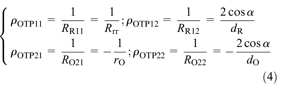
According to the Hertz theory, two mutually perpendicular planes could be obtained through the contact point of the contact pair, both perpendicular to the common section. As shown in Figure 4, the radiuses of curvature of ITP in plane 1 were expressed as RR11 and RI21, and the radiuses of curvature of ITP in plane 2 were RR12 and RI22; the radiuses of curvature of OTP in plane 1 were expressed as RR11 and RO21, and the radiuses of curvature of OTP in plane 2 were expressed as RR12 and RO22. As the curvature was the reciprocal of the radius of curvature, the curvature of ITP at the contact point was:

The curvature of OTP at the contact point was:
The sum of principal curvatures of ITP and OTP was:

The relation between eccentricity e of the contact ellipse and principal curvature function F(ρ) was 27 :
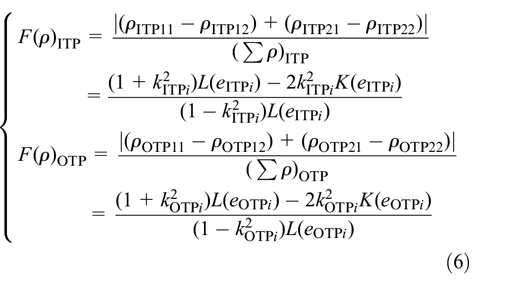
where,
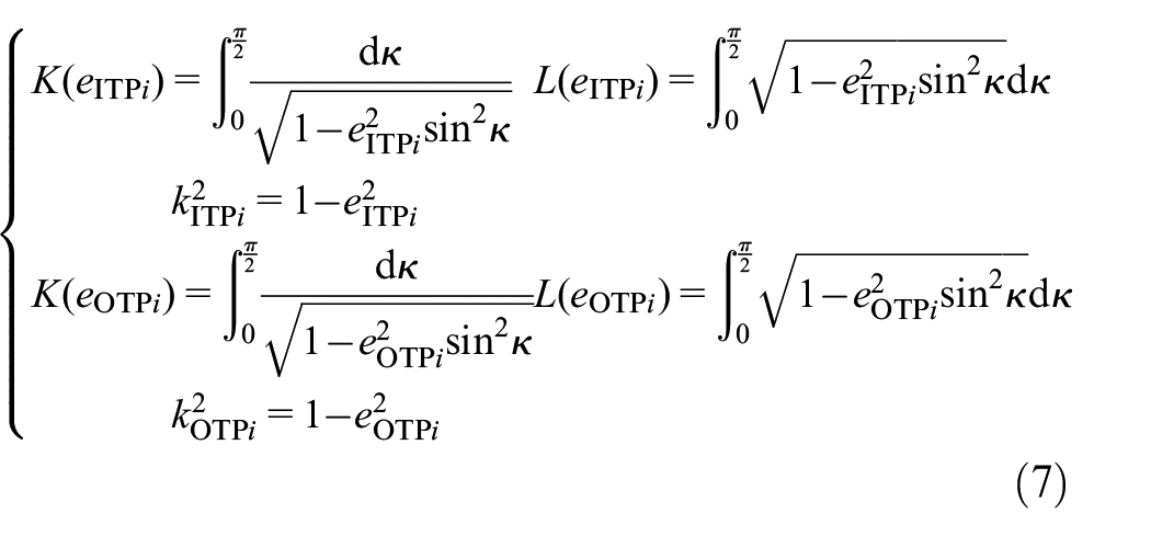
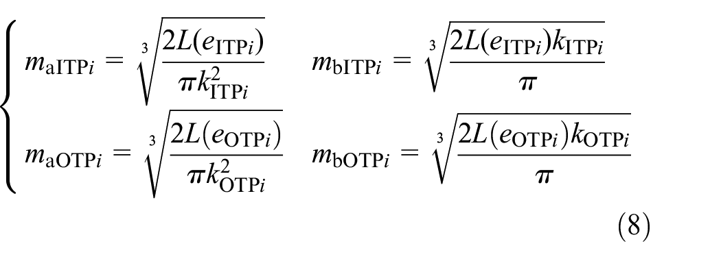
The long axis coefficient and the short axis coefficient of the contact ellipse were solved by formulas (6) and (7) 27 :
Based on the Hertz theory, the contact deformation of the semi-major axis, semi-minor axis, and center point of the contact ellipse was respectively expressed as follows:

Compressive deformation of shaft
As mentioned above, a flange structure can be installed on the inner and outer rings of PTRB to bear bilateral or unilateral axial tensile and compressive loads. However, since the stress state of shaft segments varied under different load states, the shaft segment deformation of each main bearing component was analyzed under different load states. The number of annular thread rings of threaded roller was denoted as n. There were four types of axial load states, as shown in Figure 5. The shaft segment serial number of inner and outer rings was 0 to n from left to right, and the shaft segment serial number of threaded rollers was 0 to 2n from left to right.
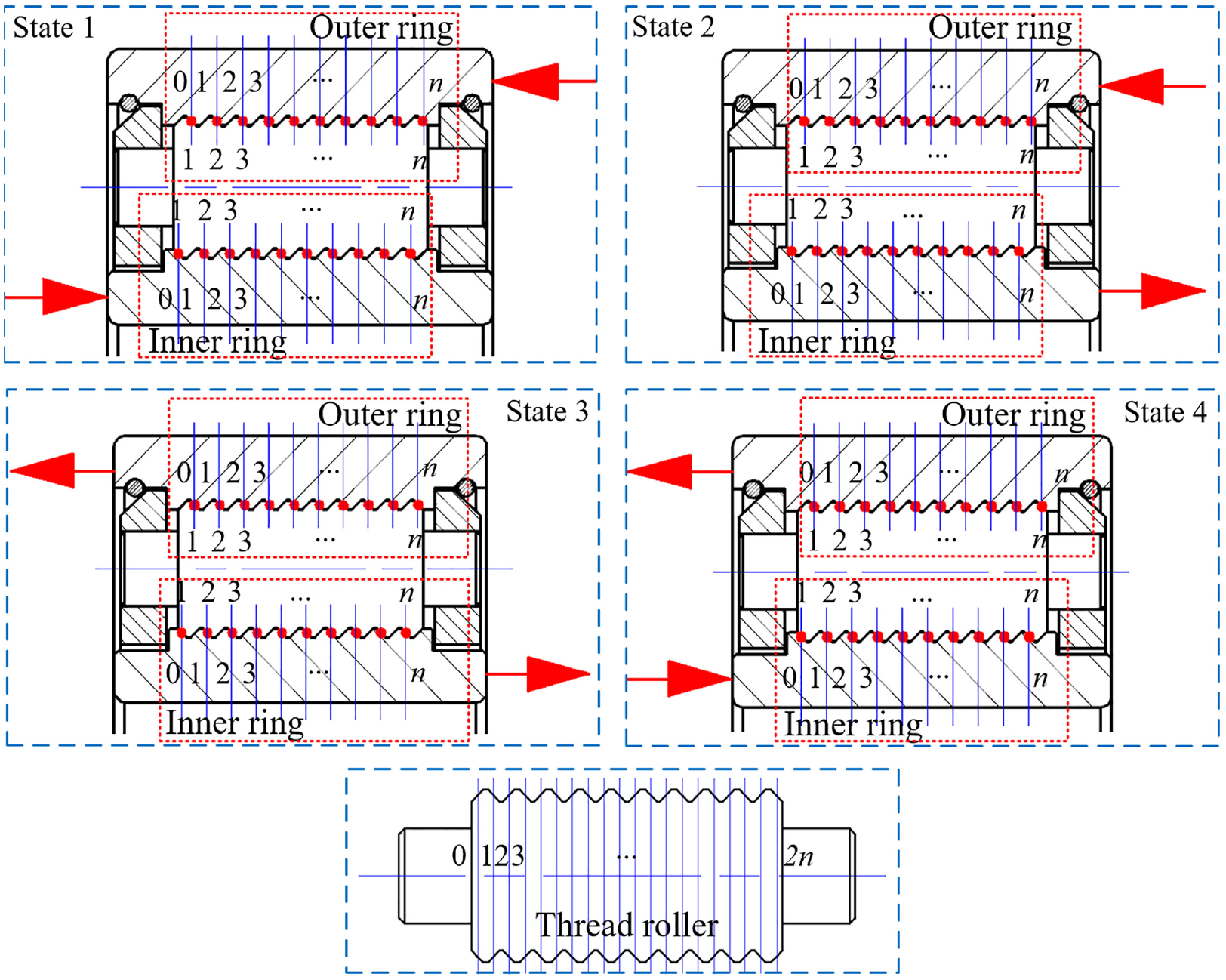
Shaft segment deformation of each main bearing component under different axial load states.
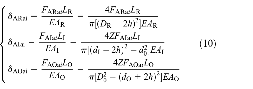
The shaft segments of threaded rollers, inner ring, and outer ring were regular cylinders. Expressing the length of shaft segment by LX, the cross-sectional area of shaft segment by AX, and the load along the axis at all shaft segments by FAXai, the shaft segment deformation amount of the threaded rollers, inner ring, and outer ring was solved based on the Hooke’s law28,29:
However, the calculation methods for FAXai were not the same under different load states. When PTRB was under axial state 1, the axial loads carried by the shaft segments of the threaded rollers, inner ring, and outer ring were FARai, FAIai, and FAOai, respectively, as shown below:

When PTRB was under axial state 2, FARai, FAIai, and FAOai were shown as follows:

When PTRB was under axial state 3, FARai, FAIai, and FAOai were shown as follows:

When PTRB was under axial state 4, FARai, FAIai, and FAOai were shown as follows:

Deformation of the thread teeth
As shown in Figure 4, elastic deformation would be generated when the thread teeth of the annular threads were under load, including bending deformation caused by bending moment, shear deformation caused by shear stress, rotational deformation caused by root tilt, slip deformation caused by root shear, and shrinkage deformation caused by radial component force. The methods for calculating thread tooth deformation were different under axial load and radial load. The specific analysis and calculation methods have been described in the author’s another paper. 30 30–32
Theoretical models of load distribution
As analyzed above, when PTRB was under axial load, the Hertz contact deformation and the thread tooth deformation of annular threads at each contact point were only related to the load at the said contact point. If the shaft segment deformation of each main bearing component was neglected, there would be no uneven axial load distribution. That is, shaft segment deformation was the main cause of uneven axial load distribution. Because the procedures for calculating the shaft segment deformation of each main bearing component varied under different axial load states, the values of the axial load distribution, axial load rating. and friction torque were different as well. Therefore, it is necessary to analyze and solve the load distribution coefficients under the four axial load states.
When PTRB was under radial load, the position of the threaded roller kept changing during motion, so the loads exerted on the threaded roller at each position were different in both direction and value. For this reason, the radial load might be unevenly distributed.
Theoretical model of axial load distribution
It was assumed that all contact points kept contacting before and after the load bearing of PTRB. As for the four axial load states in Figure 5, state 1 and state 2 had the same compatibility equation, and state 3 and state 4 had the same compatibility equation. But due to the different formulas for calculating shaft segment deformation, the axial load distribution coefficients under the four states were different.
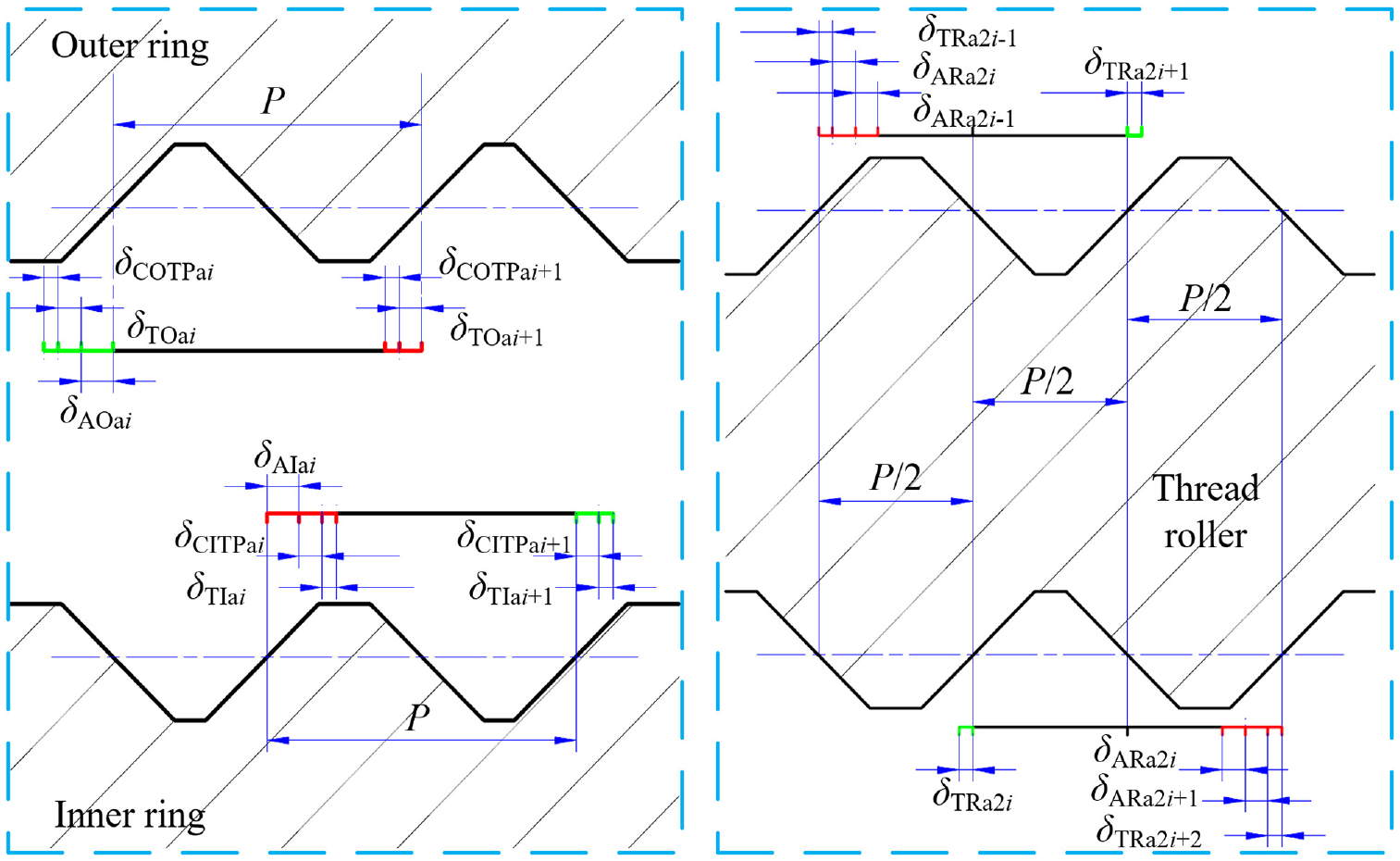
As shown in Figure 6 and 7, according to the elastic deformation relation between the inner ring and the threaded roller, the compatibility equation of ITP for state 1 and state 2 could be obtained as follows:


Elastic deformation relation of main bearing components (state 1).

Elastic deformation relation of main bearing components (state 2).
According to the elastic deformation relation between the outer ring and the threaded roller, the compatibility equation of OTP for state 1 and state 2 could be obtained as follows:

As shown in Figures 8 and 9, the compatibility equation of ITP for state 3 and state 4 was shown as follows:


Elastic deformation relation of main bearing components (state 3).
Elastic deformation relation of main bearing components (state 4).
The compatibility equation of OTP for state 3 and state 4 was shown as follows:

2n unknown contact forces were generated by the inner and outer rings that had contact with the same threaded roller. Setting i as 1 − (n − 1) in formulas (15) to (18), 2n − 2 compatibility equations could be obtained. Meanwhile, force analysis showed the relation between the component force along the axis of the normal contact load at the contact point and the axial load FPa as follows:

It meant that 2n unknown contact forces could be solved by 2n equations in formulas (15) to (19), thereby obtaining the contact load at each contact point.
For ease of analysis of PTRB’s performance, such as load rating and friction torque, the ratio of the component force along the axis of the normal contact load at the contact point to the mean axial load was defined as axial load distribution coefficient fai. Hence, the axial load distribution coefficients of ITP and OTP, fIai and fOai, were as follows:

The maximum axial load distribution coefficients of ITP and OTP were denoted as fIamax and fOamax, respectively.
Theoretical model of radial load distribution
It was assumed that all contact points kept contacting before and after the load bearing of PTRB. The analysis of PTRB’s structure and motion characteristics indicated that the position of the threaded roller kept changing during motion, and only some threaded rollers carried the load. As shown in Figure 10, when PTRB was under a vertically upward radial load, only the upper half ring of the threaded rollers carried the load. The threaded rollers under load were defined as effective threaded rollers, the number of effective threaded rollers was denoted as Ze, and the angle between the effective threaded rollers and the horizontal direction was denoted as θi. The right side of Figure 10 shows an exceptional case where the number of effective threaded rollers was the minimum, the forces on the left and right sides were symmetric, and the maximum radial load distribution coefficient could be found.

Elastic deformation diagram of the PTRB’s structure under radial load.
The angle between the first effective threaded roller and the horizontal direction was defined as θ1, and the angle of all effective threaded rollers θi was shown as follows:

Force analysis showed that the relation between the force applied to the annular threads of all threaded rollers Fri and the radial load FPr was shown as follows:

When PTRB was under radial load, the shaft deformation was neglected, and only the Hertz contact deformation and the thread tooth deformation of annular threads at the contact point were taken into consideration. When the fixed, vertically upward radial load of the outer ring was applied to the inner ring, the equivalence of the deformation amount of every two adjacent effective threaded rollers in the vertical direction was taken as a compatibility equation:

Taking in i formulas (22) and (23) as 1 − (Ze − 1), Ze − 1 compatibility equations obtained by formula (23) as well as formula (22) were used to solve Ze unknown contact forces generated when PTRB was under radial load, thereby obtaining the contact load at each contact point.
The ratio of the force applied to the annular thread of the threaded roller to the mean radial load was defined as radial load distribution coefficient fri:

The maximum radial load distribution coefficient was denoted as frmax.
Effect of load states and load values on load distribution
In this section, a specific analysis was conducted on the effect of load states and load values on load distribution by taking the PTRB prototype as an example. The specific structural parameters of the PTRB prototype are shown in Table 1.
Specific structural parameters of PTRB prototype.

The load distribution coefficient of the PTRB prototype under axial load was analyzed based on the theoretical model of axial load distribution. When the axial load was 20 kN, the axial load distribution coefficients of ITP and OTP of the PTRB prototype under the four axial load states were obtained, as shown in Figure 11. The variation ranges of fIai were 1.055–0.972, 0.959–1.068, 0.960–1.066, and 1.056–0.970, and the variation ranges of fOai were 0.987–1.027, 0.985–1.029, 1.037–0.978, and 1.038–0.976.

Axial load distribution coefficients under different axial load states.
The variation trends and values of fIai and fOai under the four axial load states were different. By comparison, the load distribution of ITP was more uneven, and fIamax was larger. For state 1 and state 3, fIai and fOai showed an opposite variation trend with the increase of contact point serial number, and for state 2 and state 4, fIai and fOai showed the same variation trend with the increase of contact point serial number. From the analysis in combination with Figure 5, for both ITP and OTP, the load distribution coefficient was the largest on the directly acting surface of the external load. That is, the load distribution coefficient was the largest at the contact point close to the flange.
The variation of fIai and fOai with the axial load could be obtained from the analysis of PTRB prototype under state 1, as shown in Figure 12. When the axial load was 20 kN, the variation ranges of fIai and fOai were 1.055–0.972 and 0.987–1.027, showing an opposite variation trend between the two and a larger fIamax. As the axial load increased from 10 to 30 kN, the degree of uneven load distribution for both ITP and OTP became larger, and fIamax remained larger. But the rates of increase of fIamax and fOamax were low, 1.145% and 0.488%, respectively. Therefore, it could be approximately considered that the axial load distribution coefficient was independent of the axial load value, and the axial load distribution coefficient could be approximately deemed as an inherent characteristic of PTRB with a certain dimension under a certain axial load state.

Effect of axial load on axial load distribution coefficient.
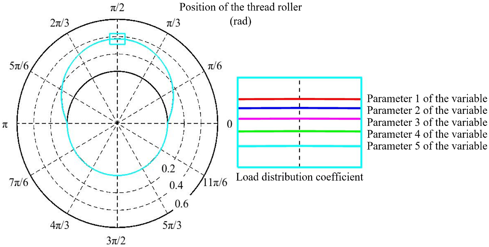
The variation of fri with the radial load could be obtained from the analysis of PTRB prototype, as shown in Figure 13. The maximum radial load distribution coefficient existed at the position where argument θi was 90°. As the radial load increased from 10to 30 kN, frmax decreased from 0.37514 to 0.37235, with an increase rate of only −0.744%. Similar to the axial load distribution coefficient, the radial load distribution coefficient could be approximately deemed as an inherent characteristic of PTRB with a certain dimension.

Effect of radial load on radial load distribution coefficient.
To verify the correctness of the theoretical model, a finite element analysis (FEA) was conducted on the PTRB prototype under state 1 (load = 20 kN) and radial load (load = 20 kN) by using an ANSYS workbench.
As shown in Figure 14, when PTRB was under axial load, it was equally cut into 11 parts to enhance the efficiency of the simulation analysis. This is because the PTRB prototype has 11 rollers. Meanwhile, when PTRB was under radial load, the analysis was only conducted under the most severe working condition, that is when only five rollers were under radial load. In the simulation model, the meshes of the contact pair were refined, and the size of the rough meshes should be no more than 10 times that of the refined meshes. In this way, the accuracy of the simulation results could be improved.

PTRB’s mesh distribution.
After the simulation, the load value of each contact pair was extracted from the ANSYS workbench, and fIai, fOai, and fIa were obtained through calculation. The simulation results are shown in Figures 15 and 16. Under state 1, with the increase of contact point serial number, the variation ranges of fIai and fOai were 1.064–0.963 and 0.980–1.041, showing an opposite variation trend between the two and a larger fIamax. For both ITP and OTP, the load distribution coefficient was the largest on the directly acting surface of the external load. Under radial load, the maximum radial load distribution coefficient existed at the position where argument θi was 90°, and frmax was 0.37335.

Axial load distribution coefficients under state 1 (simulation results).

Radial load distribution coefficients under radial load (simulation results).
Through comparative analysis, there was consistency between the calculation results of the theoretical model and the simulation results of the FEA, with a slight difference. The difference in fIamax, fOamax, and frmax were 0.85%, 1.36%, and 0.001%, respectively, demonstrating the accuracy of the theoretical model.
Effect of structural parameters on load distribution
In this section, a specific analysis was conducted on the effect of different structural parameters on load distribution by taking PTRB prototypes working under axial load state 1 and under radial load state as an example. Prior to the analysis of the effect of different structural parameters on load distribution, the value range of each structural parameter should be determined as follows:
(1) Since PTRB can bear axial load, radial load, and even axial-radial combined load, and it belongs to ball bearing through mechanism analysis, the value range of the contact angle was set to 30°–60° by referring to the contact angle value range of the angular contact ball bearing.
(2) With the dimension of PTRB being constant, the number of thread teeth per roller was inversely proportional to the distance between adjacent threads. Therefore, a large number of thread teeth would narrow the distance between adjacent threads, resulting in high manufacturing costs and the risk of sliding wire in the bearing process; and a small number of thread teeth would reduce the load rating of PTRB. In light of the theoretical analysis and processing experience, the value range of the number of thread teeth per roller was set to 8–12, and the corresponding distance between adjacent threads was set to 1.6–1.0 mm.
(3) To ensure that the contact ellipse and contacting dimension of IRP and ORP meet the Hertz theory, the contact radius of threaded roller should be no less than dR/2cosα, and the maximum value should be one order of magnitude less than the contact radius of the inner and outer rings. For ease of analysis, the value range of the contact radius of threaded roller was set to 4.5–7.5 mm.
(4) With the dimension of PTRB and the pitch diameter of a threaded roller set being constant, the pitch diameter of threaded roller was associated with that of the inner ring and outer ring. The larger the pitch diameter of threaded roller was, the smaller the pitch diameter of the inner ring and outer ring was. Considering the pitch diameter of threaded roller should be no larger than 2Rrrcosα required by the Hertz theory and the strength requirement, the value range of the pitch diameter of threaded roller was set to 4.8–7.2 mm.
(5) The minimum number of threaded rollers was three, and the maximum value was determined by the installation way of PTRB, which could be obtained by calculation according to formula (25). Given that a small number of threaded rollers might weaken the operating stability and bearing capacity of PTRB, the value range of the number of threaded rollers was set to 7–11.
Similar to the assembly method of deep groove ball bearing, the assembly method of PTRB also contains three steps: (a) firstly, the threaded rollers were closely arranged on the inner side of the outer ring, and the pitch diameter of each threaded roller was in contact with the pitch diameter of outer ring; (b) then, the inner ring was placed inside, and the axis of the inner ring coincided with that of the outer ring; (c) finally, the position of threaded rollers was adjusted to make them evenly distributed on the distribution circle, and the planet carrier was used to fix the relative position of each threaded roller. Figure 17 shows the method for installing the maximum number of threaded rollers on PTRB, and the maximum number installed Zmax was:


Installing process of PTRB.
The effect of different structural parameters on axial load distribution coefficient was analyzed under an axial load of 20 kN. The results are shown in Figure 18. Under different structural parameters, fIamax fell into the range of 1.02–1.09, fOamax fell into the range of 1.01–1.05, and the maximum axial load distribution coefficient of PTRB was no more than 1.09. The variation of the pitch diameter of threaded roller had the most significant effect on axial load distribution coefficient, with a variation rate of 7%, and the variation of the remaining parameters had a relatively small effect on the axial load distribution coefficient, with a variation rate of less than 3%.

Effect of different structural parameters on axial load distribution coefficient.
Therefore, with PTRB’s dimension and the pitch diameter of a threaded roller set unchanged, the effects of the variations of the contact angle, number of thread teeth per roller, contact radius of threaded roller, and number of threaded rollers within their value ranges on PTRB’s axial load distribution could be neglected. This is beneficial to simplify the optimization design process of PTRB’s structure with dynamic load rating, static load rating and friction torque as optimization objects, and improve the optimization design efficiency.
The effect of different structural parameters on radial load distribution coefficient was analyzed under a radial load of 20 kN. The results are shown in Figure 19 and Table 2. The different values of structural parameters in the first four groups had a minimal effect on frmax. As the parameter value changed, frmax fell into the range of 0.37587–0.37006, with an absolute value of increase rate of less than 1.5%. However, the number of threaded rollers had a significant effect on radial load distribution coefficient. When the number of threaded rollers increased from 7 to 11, frmax decreased from 0.59163 to 0.37372, helping reduce the uneven radial load distribution. Meanwhile, on the basis of analysis from a qualitative perspective, with PTRB’s dimension unchanged, a large number of threaded rollers was conducive to increasing the load rating of PTRB; with the radial load unchanged, a large number of contact points could help reduce PTRB’s friction torque.
Effect of different structural parameters on radial load distribution coefficient.
Effect of different structural parameters on radial load distribution coefficient.
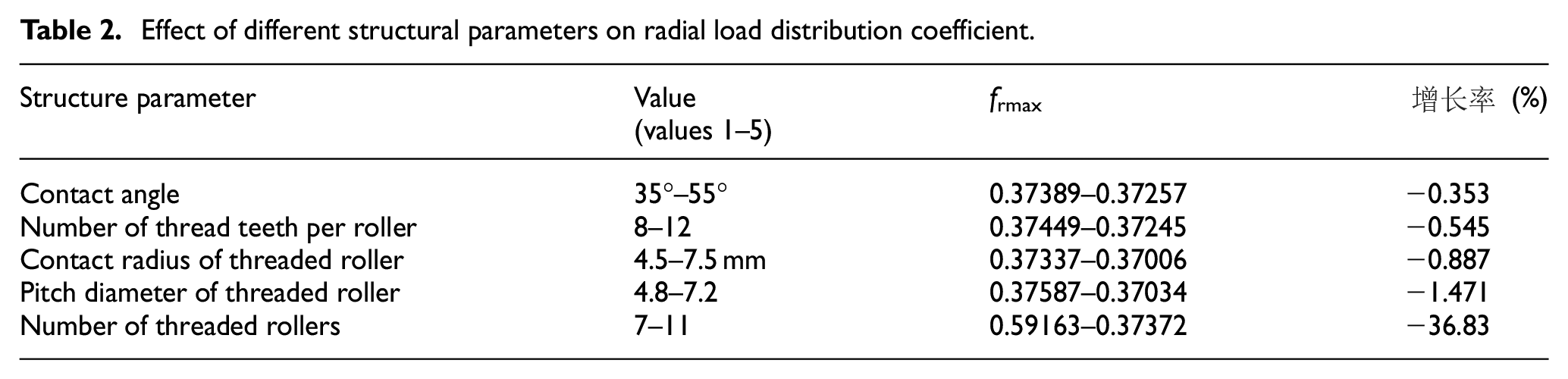
Therefore, with PTRB’s dimension and the pitch diameter of a threaded roller set unchanged, the effects of the variations of the parameters in the first four groups within their value ranges on PTRB’s radial load distribution coefficient, dynamic load rating, static load rating, and friction torque could be neglected. When the maximum number of threaded rollers was taken according to formula (25), PTRB had the optimum comprehensive performance. That is, the radial load distribution coefficient could be deemed as a constant value during the performance optimization of PTRB.
Conclusions
In this paper, a detailed analysis was carried out on the effect of different structural parameters and load states on PTRB’s load distribution. The main efforts and important conclusions were summarized as follows:
(1) A flange structure of PTRB and an integrated design solution of PTRB and PRS were presented to enable PTRB to bear bilateral, axial tensile, and compressive loads. The transmission paths of force under multiple load states were also analyzed.
(2) Based on the HertZ theory and Hooke’s law, the contact characteristics of ITP and OTP were analyzed, and the methods for calculating elastic deformation of threaded roller, inner ring, and outer ring under different load states were given. It was pointed out that shaft segment deformation was the main cause of uneven axial load distribution, and Hertz contact deformation and thread tooth deformation also had a close relation with that. However, the varying positions of the threaded roller were the main cause of uneven radial load distribution.
(3) In view of the nonlinear relation between force and elastic deformation, the theoretical model of PTRB’s load distribution was built. There was a discrepancy between the variation trends and values of fIai and fOai under four axial load states. The load distribution coefficient was the largest on the acting surface of the load. That is, the load distribution coefficient was larger at the contact point closer to the flange. As the load increased from 10 to 30 kN, the degree of uneven load distribution for ITP and OTP became larger, but the rates of increase of fIamax, fOamax, and frmax were low, 1.145%, 0.488%, and −0.744% only. Therefore, the axial load distribution coefficient and the radial load distribution coefficient could be approximately deemed as inherent characteristics of PTRB with a certain dimension under a certain axial load state.
(4) After the value range of each structural parameter was determined, the effect of different structural parameters on load distribution was analyzed. The variation of the pitch diameter of threaded roller had the most significant effect on axial load distribution coefficient, with a variation rate of 7%; the variation of the number of threaded rollers had a significant effect on radial load distribution coefficient, with a variation rate of 37%; the variation of the remaining structural parameters had a minimal effect on load distribution coefficient, with a variation rate of ≯3%.
(5) The maximum number of threaded rollers could help reduce the uneven radial load distribution, improve PTRB’s load rating and reduce its friction torque, thus obtaining the optimum comprehensive performance of PTRB. Therefore, when a follow-up optimization design is conducted on the performance of PTRB with a fixed dimension, and the contact angle, number of thread teeth per roller, and pitch diameter of threaded roller are deemed as design variables, the load distribution coefficient can be set as a constant value, and the number of threaded rollers can be set as the maximum value. This is beneficial to simplify the optimization design process of PTRB’s structure with dynamic load rating, static load rating and friction torque as optimization objects, and improve the optimization design efficiency, thus laying a solid foundation for the follow-up performance optimization of PTRB.
Footnotes
Handling Editor: Chenhui Liang
Declaration of conflicting interests
The author(s) declared no potential conflicts of interest with respect to the research, authorship, and/or publication of this article.
Funding
The author(s) disclosed receipt of the following financial support for the research, authorship, and/or publication of this article: This study has been funded by Aerospace Servo Drive and Transmission Laboratory, Beihang University.
Data availability
The datasets generated during and/or analyzed during the current study are available from the corresponding author on reasonable request.