
Abstract
In this paper, we propose a new method to use cost-effective multi-sheet off-the-shelf piezoelectric material (e.g. PZT) as an actuator for micropumps. Instead of one customized single PZT sheet that is typically expensive, multiple commercially available PZT sheets are utilized to decrease the cost of fabrication. For this purpose, we have derived analytic equations for expressing the natural frequency and mode shape of the actuator. The FEM simulations are utilized to verify the analytic equations. Thanks to their high accuracy, we can utilize the derived analytic equations as fitness functions of genetic algorithm (GA) for the optimization purpose of PZT physical aspects. Our experimental measurement results show that the GA is capable of optimizing multiple physical parameters of the piezoelectric actuator. Moreover, one-way compliant microflaps are presented for the first time to act as one-way valves for a PZT micropump aided by our proposed multi-sheet PZT actuator. The flow rate of this configuration is compared with a single-sheet PZT actuator in order to demonstrate the effect of the optimized PZT actuators in the practical applications of micropumps.
Keywords
Introduction
The concept of microfluidics was introduced over 50 years ago by IBM. 1 Later Gravesen et al. 2 published a review paper about micropumping technologies and different actuating principles. Afterward many new fabrication technologies and in turn new micropump techniques have been developed, such as the positive displacement micropump by Cunneen et al., 3 the electro-osmotic micropump by Chen et al., 4 the pneumatic polydimethylsiloxane (PDMS) micropump by Jeong and Konishi, 5 the piezoelectric micropump by Kaviani et al., 6 and the high-pressure peristaltic micropump by Loth and Förster. 7 These are just some examples of the new fabrication methods in the microfluidics area, where the micropump design is highly dependent on specific applications.
Micropumps have been serving as a device of interest for many applications such as lab-on-a-chip or organ chips. In 2019, Mi et al.’s 8 team developed a valveless electromagnetic microfluidic pump using varied internal pressures, which were actuated by vibrating a PDMS membrane. While successful, they admitted that more work would be needed to stabilize their energy supply for better control. Their device was able to reach a flow rate of 4.5 microL/min. A couple of years later, the research group under Alvarez-Braña et al. 9 worked on micropumps through 3D printing technology. They found that the material and design used to print were related to the power output of the pump. The designs they used had a maximum flow rate of 4.1 microL/min. Within the same year of 2021, Qi and Shinshi 10 focused on a bidirectional micropump, which was driven by cylindrical magnets. These magnets exerted a force on three diaphragms, which could drive the fluid at a flow rate of 8.5 microL/min forward and a flow rate of 9 microL/min backwards.
In 2022, at least two more research teams have contributed to this area. Under the leadership of Sravani et al., 11 a design was developed focusing on the use of a stacked style of single layer piezoelectric actuators within the micropump in order to maximize flow rate while minimizing power input. Their device worked at a driving frequency of 100 Hz to achieve an 800 microL/min flow rate. But no piezoelectric actuator modeling or its performance analysis was reported from this work. Nishikata et al. 12 and his group went to another direction, looking at a new waveform-driven braille actuator for smoother flow. While achieving a 7.4 microL/min flow rate, they also reduced pulsating flow by 79% and backflow in the pump by 63%.
In general, being applied a voltage, a piezoelectric (e.g. PZT) single layer bends inwards as a micropump. 13 This action can push fluid out of the chamber through the outlet valve. In the suction mode, when the voltage is removed, the PZT layer would back up to allow the fluid to enter the chamber. This reciprocating process would eventually cause the pumping action. A recent attempt of improving PZT micropump was done by Hu et al., 14 who added a new passive layer to the previous single layer design to decrease the resonant frequency as an advantage. The authors verified the finite element method (FEM) model with their experimental setup.
Moreover, an analytic modeling for a single layer circular piezoelectric actuator was developed by Mo et al. 15 They investigated the effect of the thickness ratio and the radius of the piezoelectric layer, which is bonded to a metallic layer with the maximum deflection by using their proposed analytic model. In addition, an analytic modeling method based on the thin plate theory and Kelvin–Voigt laws for a single-layer piezoelectric actuator was proposed by Monemian Esfahani and Bahrami. 16 The authors also studied the vibration of an edge clamp for a rectangular PZT actuator in a fluidic environment. Although effective, the derived analytic modeling in those two works above was not used in any follow-up optimization flow and there was no report from them on the performance comparison between single layer and multilayer piezoelectric actuators.
In the past few years, there have been many different trials involving microvalves within various projects. In 2020, Gunda et al. 17 developed a low power, proportionally controlled piezoelectric microvalve. They were able to achieve a device that could work with as high as 1 bar driving pressure with very little leakage (0.8% of the open flow). Around the same time, Bamido et al. 18 were working on thermally actuated microvalves which were meant to aid in optimizing water usage in agriculture. With their apparatus formed through soft-lithography techniques, they achieved 60% less flow rate. Near the end of 2020, another team led by Amnache et al. 19 worked on a novel idea of self-adaptive microvalves that were sensitive to environmental conditions to help minimize pumping power. While the process was proven effective, the team admitted integration of such a device onto microchips is still a challenge to overcome. Furthermore, Gong et al.’s 20 research group worked on a new on-chip liquid-metal-enabled mechanism. Through their research, they achieved a highly flexible, low leak rate device, which can be controlled to form a deformable valve boss to block the flow path.
Above we introduce the recent advancement mainly in the single-sheet PZT actuators (unimorph actuator). Harris et al. 21 presented a multilayer PZT actuator and introduced a technique for replacing the conventional bonded bulk PZT transducer. Following them, Haldkar et al.’s 22 team conducted their work on multilayer strip piezoelectric bimorphs joined with silicone diaphragm, which improved performance compared to the circular PZT actuator. They claimed the new actuator could increase the flow rate by 12 times, with a lower applied voltage. Another work was done by Liu et al. 23 to investigate a bimorph PZT actuator. They conducted both experiment and FEM simulations and observed an enhancement in the deformation. However, they did not offer a systematic design and optimization methodology, which would allow rapid estimation of critical design parameters (e.g. layer thickness) in order to enable faster development of such systems for higher performance without a need of invoking computationally expensive FEM simulations.
Despite the recent advances (e.g. the strip piezo bimorph disk technique), there is still a need for a reliable low-cost micropump. On the top of the various modeling methods achieved in the existing works above, a dedicated optimization process can even boost the performance of actuators and in turn micropumps. Toward this objective, in this paper we are motivated to analytically model and optimize a multilayer PZT actuator with genetic algorithm (GA) for the fluid pumping purpose. The optimized multilayer PZT actuator can be used in micropumps to control the flow rate. Moreover, the micropump valves can be better designed by using the proposed pseudo rigid-body model technique.
This paper is organized as follows. In Section II, the governing analytic equations of the optimized PZT layer with a bonding layer will be presented with their natural frequency and mode shape derived. In Section III our GA-based optimization flow will be discussed, while the actuator design along with FEM simulation and measurement setup will be presented in Section IV. In Section V, we discuss the design of a typical micropump with either a single-PZT-sheet actuator or a double-PZT-sheet actuator. Then the experimental results will be presented in Section VI. Finally, a conclusion is drawn in Section VII.
Analytic modeling
The primary purpose of an optimized piezoelectric actuator is to provide sufficient bending displacement in the transverse direction. As illustrated in Figure 1, a piezoelectric (e.g. PZT) layer, which might be physically implemented by multiple PZT sheets, is glued with the diaphragm layer. These two layers are assumed to connect each other by a massless and linear epoxy bonding layer. The radius of the PZT layer and bonding layer is

Schematic view of a typical piezoelectric actuator.
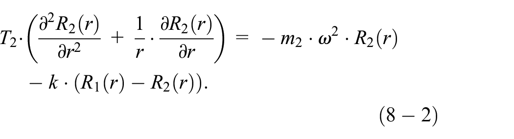
To derive the analytic expression of the natural frequency and mode shape, the dynamic behavior of the actuator has to be studied. By utilizing the Lagrangian method, we can derive the axisymmetric governing equations as follows 6 :
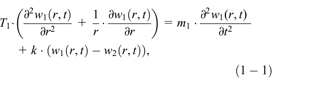

where

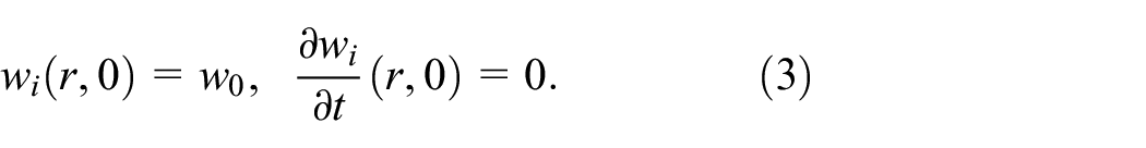
Moreover, the PZT layer has no initial velocity:
By applying the separation variation method,


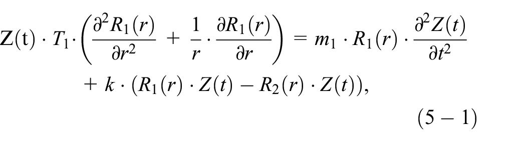

Let’s assume

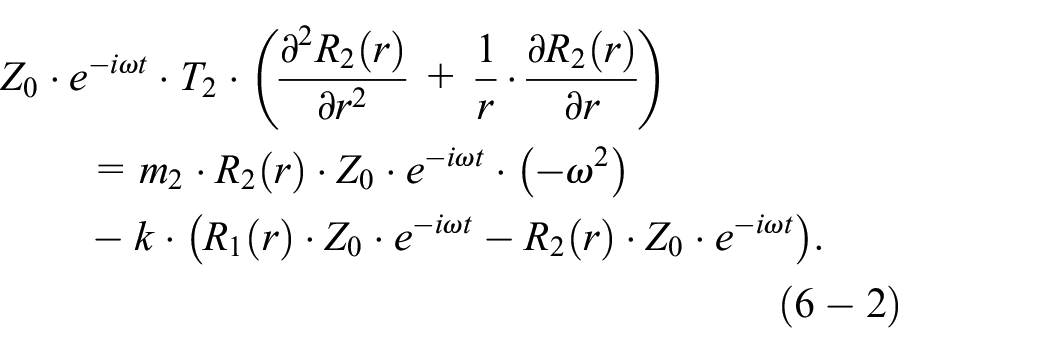
These equations can be rewritten as:


With simplification:

Let’s define


By eliminating

where

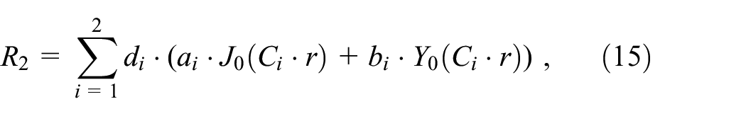
The solution of this equation can be represented as the sum of the roots from the Bessel function as follows:


where

where

By applying the first boundary condition, because of

or in the matrix form:

In order to have a non-zero solution in (18), the following condition must be satisfied:

In the end, the characteristic equation will be obtained as:

where


where

Optimization algorithm
The genetic algorithm (GA) is an evolutionary computation algorithm for optimizing sophisticated problems by mimicking biological evolution. 24 As depicted in Figure 2, the GA optimization starts with the initialization block, where the variables are coded in the form of fixed length binary strings. Each variable can be randomly selected with equal probability. Usually, the first operator that performs on a population is the reproduction, which strives to find appropriate individuals in a population and interpolate them into a mating pool. A number of methods for individual selection have been proposed in the literature, although the main idea of this operation is to choose, duplicate, and insert certain preferable individuals from the current population into the pool. The next operator within GA is the crossover, where typically two individuals are selected from the mating pool and a certain quota of these individuals are exchanged in between. In other words, the recombination between these pairs produces new individuals, called offspring. Finally, the mutation operator is performed to change 1 b from 1 to 0 or vice versa. This process is also random with a very low probability (called mutation rate) on the entire population.

Working mechanism flowchart of the GA optimization algorithm.
All the three genetic operators above are performed on the entire population in one GA generation. Thus, the search and optimization aspect of GA is mainly provided by the crossover and mutation operators. The multi-dimensional search capability offered by GA can effectively prevent it from being entrapped by local optima. Therefore, a significant feature of GA in comparison with the conventional optimization approaches is its advantageous access to the global optimum. In this study, our proposed GA-based optimization method is performed to identify the best physical aspects of the piezoelectric layer to increase the displacement of the diaphragm. The coverage of the electrodes is defined to be identical to the size of the piezoelectric film. In the following section, the capability of the GA-based optimization methodology will be further studied.
Actuator design
Since the analytic equations, which show the relationship among the thickness of the piezoelectric layer, the thickness of the diaphragm layer, the radius of the layers, and the maximum deflection of the layers as discussed in Section II, are able to accurately estimate the thicknesses of the piezoelectric and diaphragm layers in addition to the radius, we have deployed them (mainly (21-2)) as a fitness function of our GA optimization algorithm. We may include multiple physical variables as optimizable parameters such as the piezoelectric thickness (
We have implemented the GA-based optimization method in MATLAB by using its genetic algorithm tool box (Version 2017) in order to enhance the vertical displacement amplitude of the layers. The applied fitness function and constraints of the optimization are defined by (22):
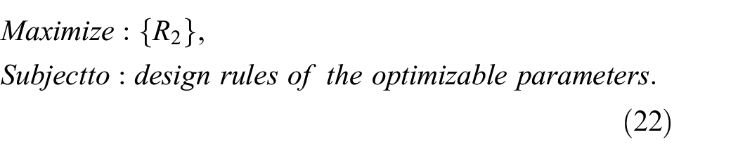
For the optimizable physical parameters (e.g.
The optimization and input parameters of the system.

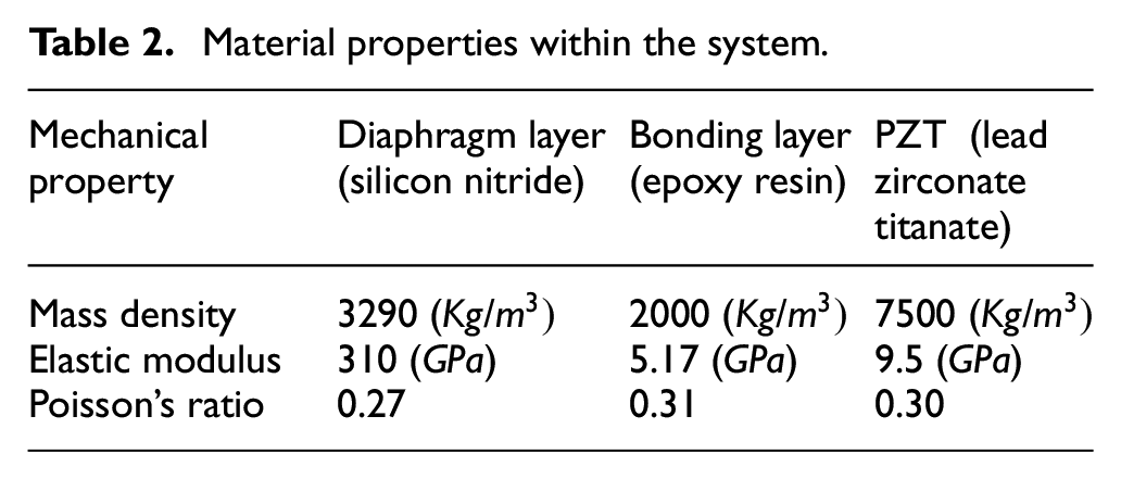
Material properties within the system.
In order to calculate the natural frequency by using the analytic method, equation (20) must be solved. By solving this simple algebraic Bessel function, natural frequency

The natural frequencies of the optimized PZT layer (Group-1) in COMSOL Multiphysics: (a) the first mode shape, (b) the second mode shape, and (c) the third mode shape.

The natural frequencies of the multiple PZT sheets along with the epoxy bonding layer (Group-2) in COMSOL Multiphysics: (a) the first mode shape, (b) the second mode shape, and (c) the third mode shape.
Table 3 shows the comparison between the multi-sheet model and the optimized model. The absolute percentage error (APD) is calculated by using the following equation:

Comparison of the first, second, and third natural frequencies and mode shapes from the FEM simulations.

where
As listed in Table 4, the natural frequency comparison between the analytically computed model and the FEM simulation for the optimized unimorph piezoelectric actuator above shows the acceptable accuracy of our proposed analytic model. We can see that this analytic model is very valuable, since the designers can use it to estimate the natural frequencies of a new system configuration with different geometric dimensions very efficiently and then realize it with the cost-effective off-the-shelf commercial PZT sheets without any computationally expensive FEM simulations. Moreover, the transverse vibration of the optimized PZT layer can be turned into a time-dependent vibration when the input voltage signal changes as a function of time. Thus, the designers may opt to determine the best input signal, which can maximize the efficiency of the system. In order to reach this goal, after calculating the natural frequencies, the first natural frequency will be chosen to apply to the system. A high voltage signal with the same frequency
Comparison of the first, second, and third natural frequencies between the analytic computation and FEM simulations for the optimized unimorph piezoelectric actuator.

To verify the accuracy of the proposed model, we have built up an experimental measurement setup. A high voltage signal (i.e.

Tresca stress at the boundary and displacement profile.
The experimental measurement setup, as shown in Figure 6, includes a fixture, a high-precision laser measurement sensor (LK-H022, resolution of 0.02

Experimental measurement setup: (1) Double PZT sheets, (2) Fixture, (3) Shaker, (4) High-precision laser measurement sensor (LK-H022, resolution of 0.02 μm), (5) Signal generator, (6) High-precision high-voltage power amplifier (TEGAM-2350), and (7) Data acquisition system.
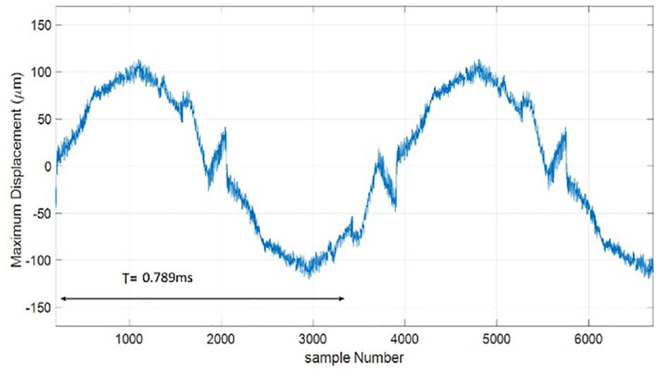
The center displacement response of the system under excitation signal of
Micropump design
In this section, the double-PZT-sheet actuator has been modeled onto a micropump to explore the effect of this optimized actuator on the flow rate of the micropump. A typical configuration of the micropump with the double-PZT-sheet actuator is modeled as shown in Figure 8. In order to design the microvalve, the pseudo-rigid-body model will be introduced. The purpose of the pseudo-rigid-body model is to provide a simple method for analyzing systems, which are under large nonlinear deflections. The pseudo rigid-body model concept is used to model the deflection of flexible segments by using rigid-body segments, which have the same force-deflection characteristics. 25

Schematic view of micropump with one-way compliant microflaps.
For each microflap, a pseudo rigid-body model can evaluate the deflection path of the flexible microflap. The motion will be modeled by rigid links attached at pin joints. Figure 9(a) shows the original and deflected position of microflap, while Figure 9(b) illustrates the pseudo rigid-body model. In this model, the spring is added in order to accurately predict the force-deflection relationship of the compliant microflap. The spring constant and deflection, and stress can be calculated as follows:


(a) Schematic view of microflap, (b) pseudo rigid-body model of microflap, and (c) the FEM modeling of microflap.
where k is spring constant, E is the Young’s module,


where
The maximum pressure that can be produced by the double-PZT-sheet actuator under excitation signal of
For fabrication of microflaps and micropump, we propose using PDMS, which is able to provide unmatched advantages, including optical transparency, bubble permeability, quick and low-cost processing. PDMS, which typically mold and reversibly bond with very good elasticity, can be used for leak-free valving. In contrast, silicon is opaque, bubble and gas impermeable, and known for its expensive fabrication process. Another reason why PDMS is chosen in this study is its ability to form valves without leakage. Although the silicon nitride or other inorganic materials have been used in the previous studies from the literature, they actually cannot provide reliable seal due to surface roughness and particles. However, the PDMS valves are able to provide more reliable sealing in presence of back pressure.
Figure 10 illustrates the fabrication process of microfluid pump with one-way compliant microflaps. Fabrication starts with the first wafer substrate (step 1), followed by the deposition of a photosensitive resist substrate (step 2). The photoresist is photolithographically patterned (step 3) and developed. The PDMS will be first degassed and then is poured on top of the first wafer (step 4), cured, and then will be separated (step 5). The PDMS piece containing the inverse of the molded feature, which includes the micropump chamber and microflaps, is then attached to the second and third wafer to form enclosed chamber (step 6). Finally, the optimized double-PZT-sheet actuator will be placed on the top of the second substrate in step 6.

Process for fabricating microfluid pump with one-way compliant microflaps using PDMS.
Experimental results
After designing the microflap, the double-PZT-sheet actuator micropump has been modeled in COMSOL Multiphysics as shown in Figure 11. The fully coupled fluid-structure interaction (FSI) COMSOL Multiphysics module is utilized to combine the fluid flow, which is formulated by using an Eulerian description and a spatial frame, with the solid mechanics, which is formulated by using a Lagrangian description and a material frame. 26 Figure 11(a) shows the micropump chamber in the suction mode, while Figure 11(b) exhibits the chamber of micropump in the pump mode. In those figures, the first and second color bars on the right show the velocity and stress, respectively.

The FEM modeling of the micropump with the double-PZT-sheet actuator: (a) the suction mode and (b) the pump mode.
In order to investigate the effect of the double-PZT-sheet actuator on the system, the flow rate is calculated by FEM simulations. Figure 12 shows the flow rate of the micropump. As can be seen from this figure, the maximum flow rate reaches up to
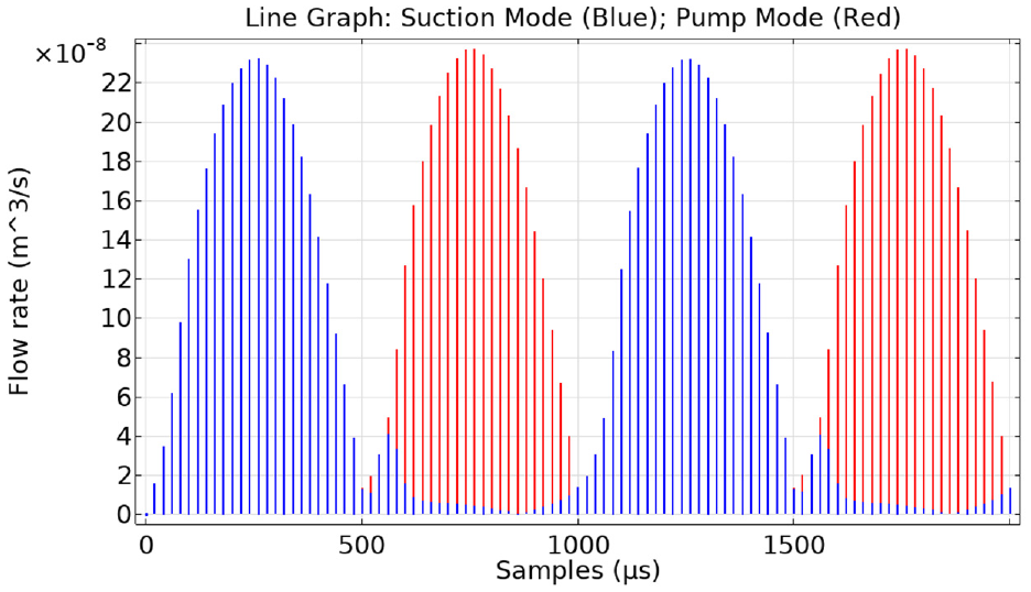
The outlet and inlet flow rates of the micropump with the optimized double-PZT-sheet actuator.

Inlet and outlet velocity of the micropump with our optimized double-PZT-sheet actuator.
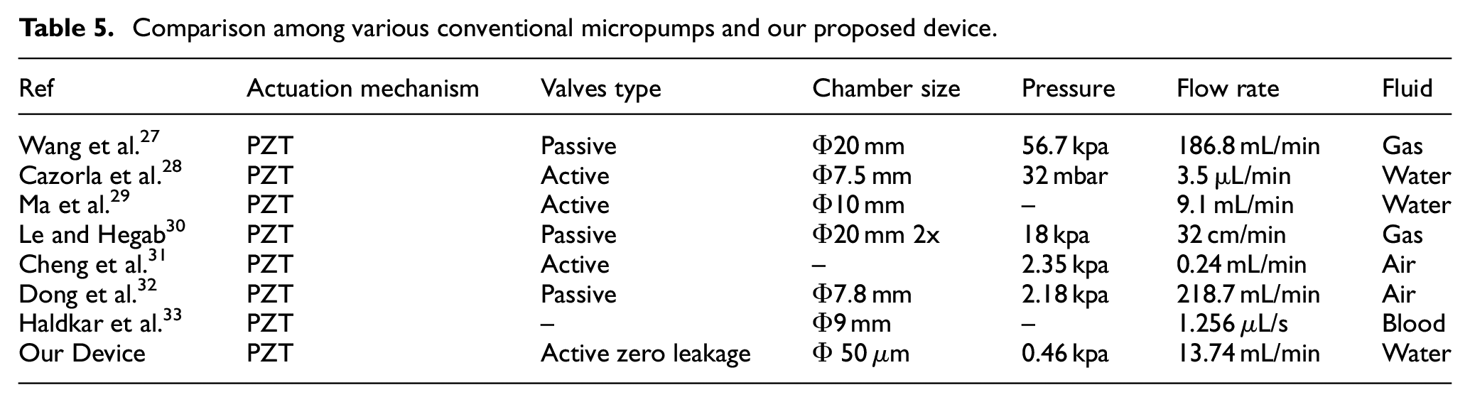
Comparison among various conventional micropumps and our proposed device.
Conclusion
In this paper, we designed and optimized a PZT layer as an actuator in addition to microvalve for the micropump. The analytic analysis of the PZT-layer-based actuator was first conducted and then verified by using FEM simulations and experimental measurement. The comparison between the analytic computation and COMSOL Multiphysics simulation reveals the high accuracy of our proposed analytic solution, whose error is less than 2% for the first natural frequency. This is valuable since the designers can efficiently estimate the natural frequencies and mode shapes of a new configuration with different dimensions and further design the microflaps by using our proposed analytic solution without depending on any computationally expensive FEM simulations. Moreover, an experimental setup was established to measure the maximum displacement for a comparison with the FEM simulation. The results show that the difference between our experimental measurement and FEM simulation is less than 4%. Furthermore, the optimized actuator was applied to a typical micropump to evaluate its functionality. The comparison between a regular micropump with a single-PZT-sheet actuator and the same micropump with our optimized double-PZT-sheet actuator reveals that the flow rate could be increased up to 14.7 times in addition to zero leakage. The future research work includes the optimization of the entire micropump as well as the validation of the micropump advanced fabrication process.
Footnotes
Acknowledgements
The authors would like to thank Prof. A. Fisher, Dr. V. Masek and Dr. A. Nasiri for helping enable the associated laboratory case study in the Faculty of Engineering and Applied Science at the Memorial University of Newfoundland.
Handling Editor: Chenhui Liang
Declaration of conflicting interests
The author(s) declared no potential conflicts of interest with respect to the research, authorship, and/or publication of this article.
Funding
The author(s) disclosed receipt of the following financial support for the research, authorship, and/or publication of this article: This work was supported partially by the Natural Sciences and Engineering Research Council of Canada, the Canada Foundation for Innovation, the Research and Development Corporation of Newfoundland and Labrador through the Industrial Research and Innovation Fund and Arctic TECH R&D Award, and the Memorial University of Newfoundland.