
Abstract
In this paper, the dynamic model between input electric signal of hydraulic valve and boom luffing angle is established, and luffing control of flexible boom of mobile elevated work platform (MEWP) is studied. The control input gain for the luffing motion of the MEWP is extremely difficult to solve and varies with boom length, work platform load, and luffing angle. For the variable control input gain, all low-order state quantities, rigid-flexible coupling quantity, and control input are included as the “total disturbance” to be observed. Based on the third-order linear tracking differentiator and the first-order ordinary differential linear equation, an active disturbance rejection controller without control input gain is proposed. With the bandwidth-based parameter settings, the controller only needs to adjust two parameters. As a comparison, this paper analyzes in detail the proposed controllers, the fixed input gain active disturbance rejection controller and the PID controller in terms of tracking error, overshoot, setting time, tracking stability, and robustness.
Introduction
Mobile elevated work platform (MEWP) is used to transport operators, tools and materials to the workplace, including self-propelled MEWP and vehicle mounted MEWP. As the demand for large heights increases in the market, the boom lengths of MEWP are becoming larger and larger. For example, for self-propelled MEWP, such as JLG 1850SJ, the platform height exceeds 56 m, and for vehicle mounted MEWP, such as Bronto S104HLA, the working height exceeds 100 m. To ensure the safety and comfort of operators on the work platform, the vibration of the boom must be strictly controlled and reduced. At present, the most common method is to reduce the speed, for example, the standard stipulates that the raising and lowering speed of the working platform should not exceed 0.4 m/s. 1 However, as a large workspace service robot, it is very important to increase the speed of MEWP, especially for rescue, firefighting, and other use cases. At present, MEWP is mostly operated by open-loop control structure, and the control accuracy depends heavily on the experience of operators.
MEWP’s boom luffing motion can be categorized as flexible linkage motion control, for which there has been much literature on modeling and control design. The control strategy of flexible manipulator system can be divided into feedforward control and feedback control. Feedforward control technology is mainly used to suppress vibration caused by input commands, mainly including filtering technology2–4 and input shaping.5,6 The filter is used for preprocessing the input signal and can be realized by using a low-pass filter or a band stop filter. Input shaping is to convolute a desired command with an impulse sequence called an input shaper, and then drive the system with the shaping command generated by the convolution. Compared with filtering technology, input shaping can achieve higher vibration reduction level and robustness.2,7 Li et al. 8 proposed a hybrid controller combining input shaping technology with adaptive active disturbance rejection controller. Ju et al. 9 introduced the full-state feedback controller on the basis of the ZV input shaper to control the elastic vibration of a flexible manipulator with variable loads. However, the design of the input shaper needs to obtain the natural frequency and damping ratio of the system in advance, and the effect of the shaper mainly depends on whether the modal parameters of the system can be accurately identified. Therefore, adaptive input shaping based on modal parameter identification is widely used for systems with varying modal parameters during operation.10–13İlman et al. 14 combined machine learning with input shaping to produce more accurate shaping design.
From the above analysis, we can see that although feedforward control can reduce the vibration caused by improper operation of the operator. However, the increased number of sensors and identification algorithms for accurate identification of modal parameters undoubtedly increase the cost and complexity of the control system. For example, for MEWP, in order to identify the modal parameters accurately during luffing, it is necessary to know the length of the boom, the angle of luffing and the load capacity of the working platform. More importantly, smoothing of input commands can suppress vibration caused by operator mishandling, but cannot do anything about vibration caused by external disturbing forces applied directly to the boom. Disturbances such as wind and unexpected force on the platform cannot be compensated for by feedforward control. Hence, a feedback loop is needed to stabilize the system around the reference trajectory to actively damp the oscillations.
Among various feedback control methods, because the structure of the single-link flexible manipulator is relatively simple, model-based control methods have been widely studied, such as singular perturbation method,15–17 sliding mode control,18–20 robust control,21,22 LQR,23,24 etc. In these literatures, the mathematical model of flexible manipulator is established by homogeneous beam or concentrated mass. For the multi-section telescopic boom structure of MEWP, Kharitonov et al. 25 proposed a model based on a uniform Euler-Bernoulli beam. The uniform beam is a strong simplification, and to achieve higher model accuracy, Pertsch et al. 26 and Zimmert et al. 27 chose segmental Euler-Bernoulli beams to model the telescopic boom. However, in the above literature, the luffing drive system of the boom is not modeled in combination with the hydraulic drive system. Instead, the luffing drive system of the boom is simplified to a drive hub with rotational inertia, and it is assumed that the boom rotates around the luffing drive hinge point. However, this is not the case. The boom rotates around the hinge point connected with the turntable, and the luffing driving torque is nonlinear. With the changes of boom length, luffing angle and working platform load, it is difficult to obtain an accurate mathematical model.
There are also many model-free controllers used for the control of flexible manipulators, such as PID and improved PID,28–30 model free predictive control,31,32 neural network,33–35 ADRC,36,37 etc. Among those control methods, the ADRC proposed by Han 38 has simple structure and excellent disturbance rejection performance, forming a new paradigm for feedback control systems. 39 Although ADRC requires few models, the order of the system and the control input gain are necessary. In addition, although the nominal control input gain of the controller design does not need to be the same as the ideal control input gain, its error has a certain range. 40 However, during the luffing motion of MEWP, the control input gain varies as the boom length and work platform load changes. Even for a single luffing process with a fixed boom length and working platform load, the control input gain still varies due to the nonlinearity of the hydraulic system and the drive torque. It is difficult to obtain satisfactory control performance with a fixed control input gain. Morales et al. 41 proposed an algebraic parameter identification technique to extract unknown time-varying input gain. Considering the uncertainty of control input gain, Fareh et al. 36 improved the PD control law of conventional ADRC to sliding mode control. Chen et al. 42 designed a new ADRC control system without input gain by designing an extended state observer and observing the control input as “total disturbance.” When the input gain is changed, the new ADRC control system can achieve better track tracking effect than applying fixed input gain. However, the designed controller needs to refer to the differential signal of each order of the reference signal.
In this paper, a more concise ADRC without input gain control is proposed. Although a detailed mathematical model is not required, the order of the control system is necessary. Therefore, first, a flexible boom luffing dynamics equation containing a hydraulic drive system is developed. Then, starting from the tracking differentiator, the differential signal of each order of the tracking differentiator is taken as the ideal state vector of the system, and then the ideal control output is derived. By constructing the first-order linear differential equations of the actual control output and the ideal control output, the fast following of the actual control output to the ideal control output is realized. Further, an extended state observer is built to observe the low-order state quantities, the rigid-flexible coupling and the control output as “total perturbations.” Finally, the observed values are used to replace the state vectors of the tracking differentiator, and the control law without control input gain is obtained. The final control law does not need the differential signal of each order of the reference signal. The main contributions of the paper are presented as follows.
(1) The dynamic equation of boom luffing motion including hydraulic drive system is established, instead of just simplifying the drive mechanism as a drive hub with rotational inertia. Based on the newly established dynamic equation, it is obvious that the control input gain has nonlinear uncertainty.
(2) Based on a linear tracking differentiator and a first-order linear ordinary differential equation, an ADRC without control input gain is proposed. The signals of each order of the tracking differentiator are used to construct the ideal control input, and the linear differential equation is used to make the actual control input converge asymptotically to the ideal one.
(3) The tracking and disturbance rejection performance of the proposed ADRC is analyzed. Despite the large range of model parameter changes, the proposed ADRC has good tracking consistency, and for a variable control input gain plant, it has better tracking stability than conventional ADRC.
The rest of this paper has the following organization. In Section 2, the dynamic model of boom luffing motion is established. In Section 3, a new ADRC without control input gain is proposed. In Section 4, the numerical verification is given. The conclusion is presented in Section 5.
Dynamic models
Dynamic models of boom luffing motion
In the modeling, the boom system is simplified as follows: (1) the area consisting of the rotating hinge point
The system of the MEWP in the luffing plane is shown in Figure 1. Taking the articulation point between the boom and the turntable as the coordinate origin O, the X-axis parallel to the ground over the point O, the Y-axis perpendicular to the ground,
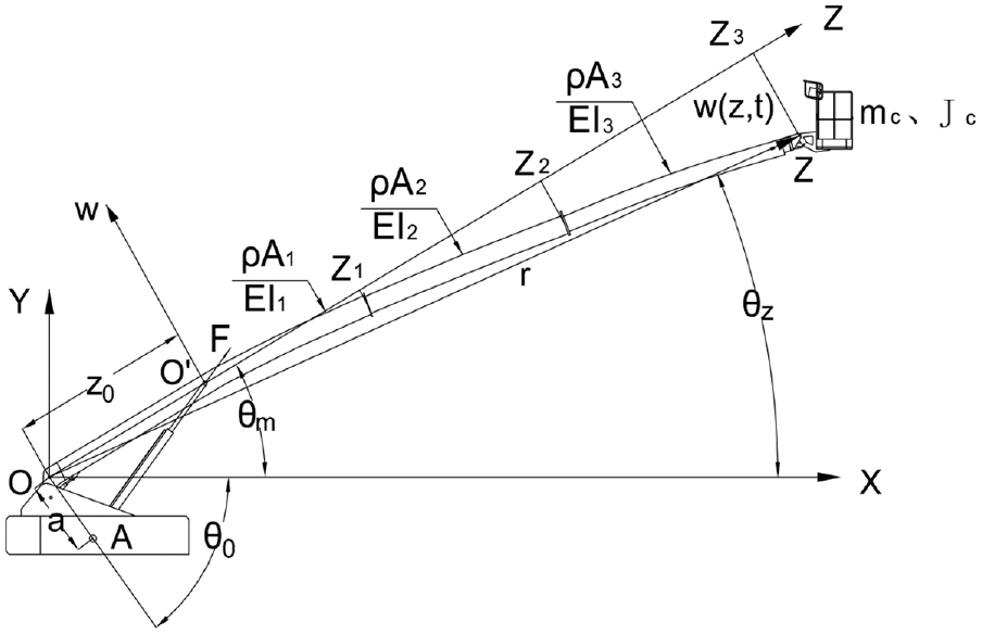
Sketch map of boom luffing.
The vector diameter of the deformed Z at any point on the telescopic boom can be expressed in the inertial coordinate system

Considering that the boom is a small deformation and

The angle

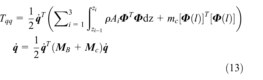
Then the kinetic energy

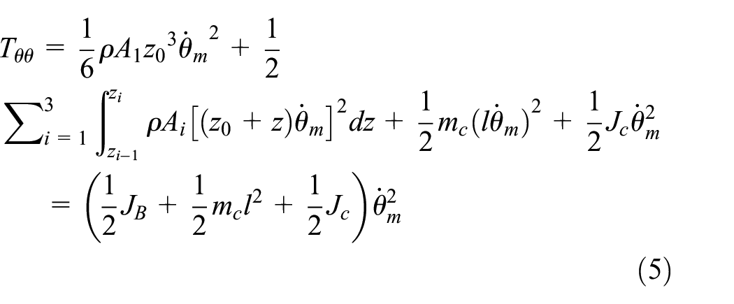
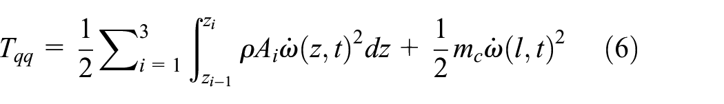
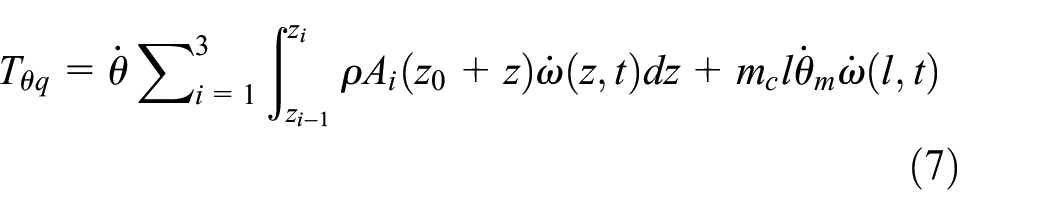
Where
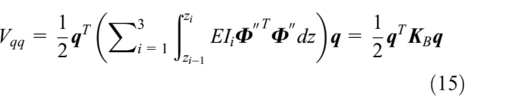
Considering the elastic potential energy and gravitational potential energy of the boom, the total potential energy V is:


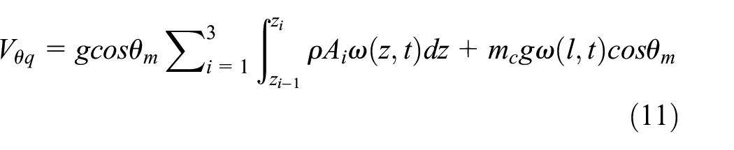
Where
According to the hypothetical modal method, the deformation

Where
Then


Where
Introducing the Lagrangian function


The differential equation of motion of the system is obtained after the arithmetic collation.


Where
From equations (19) and (20), we have that:

After increased order, equation (21) can be rewritten as:

Dynamic models of hydraulic system
From Figure 1, according to the geometric relationship, it can be obtained that:

Where
Neglecting the internal leakage and external leakage of the hydraulic cylinder, the dynamic equation of the pressure flow in the hydraulic cylinder is 43 :
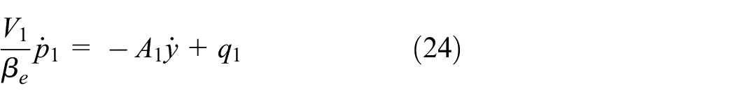
Where
The specific principle of the hydraulic system is shown in Figure 2, the supply pressure is


Hydraulic schematic diagram.
Where
Combining equations (23)–(27), the relationship between the boom drive torque

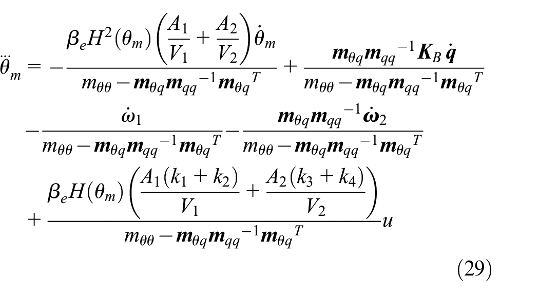
Bringing equation (28) into equation (22), the kinetic equation of the boom rotation angle
ADRC design without control input gain
Based on the formulation in the literature, 39 equation (29) is written in the standard form of the conventional ADRC as:

Where
From equation (30), we can see that it is difficult to solve for the control input gain b, and b varies with the boom length, work platform load, and boom variation angle, making it impossible to derive an exact value.
Dynamic design of control outputs
First, with reference to the third-order linear tracking differentiator, 44 the differential signals of each order of the reference input signal are designed, and the differential signals of each order are used as ideal state vectors.

Where
Bringing equation (31) into equation (30), the ideal control signal is obtained as follows:

Assume that the actual control signal

According to equation (33), if
ESO design
Write equation (30) in the form of the equation of state:

Where
Since both the control input gain

Where
For equation (35), the following state observer is designed to estimate the state vector:

Where
Now, by replacing each state vector with the observation of equation (36), equation (33) can be expressed as:

Finally, according to the literature, a is expressed as
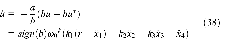
Where
Numerical verification
In the previous literature, the plant is often written in the form of transfer function, but for complex plant, the transfer function is difficult to be derived accurately. From the perspective of engineers, this paper focuses on the design of the physical system itself rather than the tedious mathematical modeling, builds a complex system model in Simcenter AMESim, and carries out simulation calculation and in-depth analysis on this basis.
Model design
The system model is constructed in Simcenter AMESim by combining equations (36) and (37) as well as the boom luffing structure diagram in Figure 1 and the hydraulic schematic diagram in Figure 2, as shown in Figure 3.

Overall model of luffing system.
The structure of the flexible boom in the model is shown in Figure 4, which consists of three sections of booms, the first section is the fixed boom, and the second and third sections are the telescopic booms. The model of the flexible boom can be obtained by importing the data obtained from the modal analysis of the finite element software into Simcenter AMESim.

Sketch map of boom.
The settings of each parameter in the model are shown in Table 1.
Model parameters.

Performance analysis
Track tracking capability analysis
In this paper, we design the reference input signal

Luffing movement time.
Controller parameters.

The analyzed working condition is full extension of the boom and maximum load capacity (
From Figure 6, PID has the fastest tracking speed, but its overshoot is greater than C_ ADRC and P_ ADRC. P_ ADRC has a lag in tracking. The faster the luffing speed, the more obvious the lag is, but the time to reach the stable state is faster than that of PID and C_ ADRC. In addition, it is obvious (Figure 6(c) is the most obvious) that the control input gain b changes in the process of luffing, resulting in the uneven tracking speed of PID and C_ADRC. At the beginning of tracking, the lag is the largest, and then the tracking speed is accelerated. Once the overshoot occurs, the tracking speed is reduced. This situation will lead to rapid changes in the speed of the work platform and affect the comfort and safety of the operator. However, P_ADRC has the best tracking stability, which can also be seen from Figure 7.

Angle tracking capability of three controllers at different speeds: (a) Δt = 65 s, (b) Δt = 35 s, and (c) Δt = 15 s.

Vertical speed of working platform (Δt = 15 s).
Figure 8 shows the acceleration of the working platform at the time of tracking stop. It is obvious that the acceleration value using PID controller greater than P_ADRC and C_ADRC.

Vertical acceleration of working platform at the stop time of track tracking: (a) Δt = 65 s, (b) Δt = 35 s, and (c) Δt = 15 s.
Table 3 shows the comparison of P_ADRC, C_ADRC, and PID in terms of maximum absolute error (MAE) obtained, the root mean square error (RMSE), the overshoot (OS), the settling time (ST), and the maximum acceleration of working platform (MA). It has been found that the P_ADRC has a superior performance compared to C_ADRC and PID in terms of OS and ST. On the other hand, PID has the lower MAE and RMSE because the integral action. However, for MEWP, we are more concerned about the comfort of operators, such as acceleration index, both P_ADRC and C_ADRC are significantly better than PID.
Comparison of P_ADRC with C_ADRC and PID at different luffing speeds.

Anti disturbance performance analysis
Change working condition: the boom is fully retracted and the working platform is unloaded (
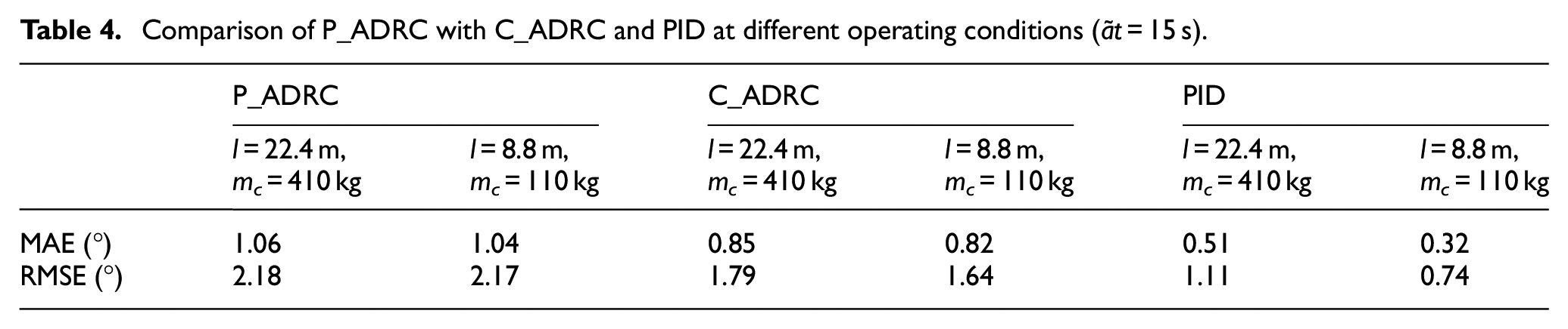
It can be seen from Figure 9 and Table 4 that the trajectory following ability of P_ADRC is almost unaffected when the boom length and the working platform load are changed. It means that P_ADRC has better robustness to the parameter changes of the plant.
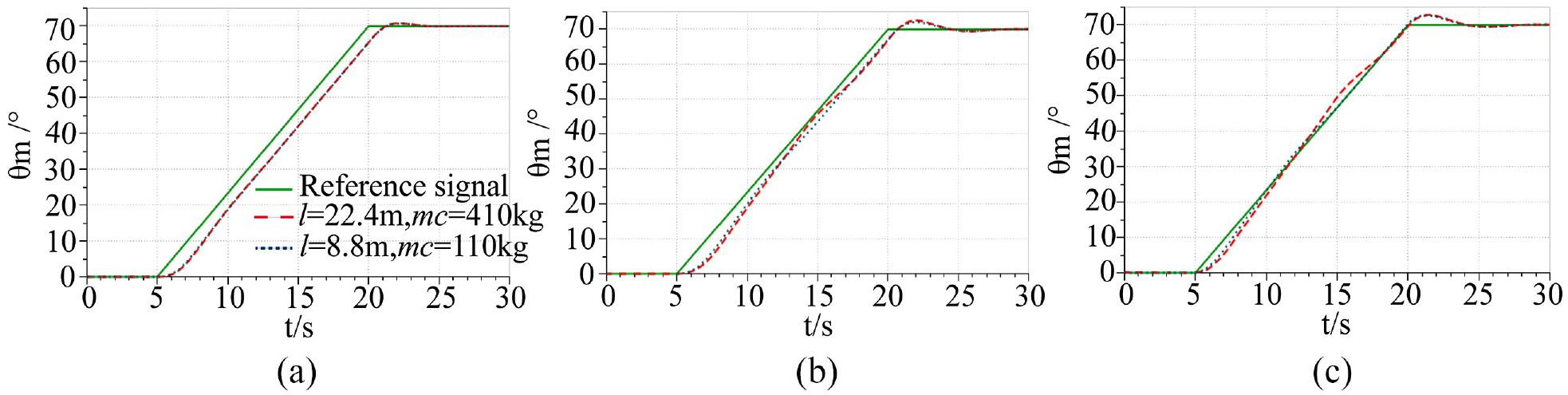
Comparison of tracking performance of controllers when the boom length and the working platform load weight change (Δt = 15 s): (a) P_ADRC, (b) C_ADRC, and (c) PID.
Comparison of P_ADRC with C_ADRC and PID at different operating conditions (Δt = 15 s).
Anti disturbance capability under step disturbance
Solazzi 47 described an accident of a MEWP during pruning operation “A big branch of three fell down and bumped the basket of MEWP.” This paper analyzes this. The analysis condition is taken as the boom is stabilized in the horizontal position and subjected to a step disturbance of 100 kg at a certain moment.
At this time, in order to suppress the vibration quickly, the boom head angle is used as the feedback control quantity. Figure 10 shows the comparison of the stability capability of the three controllers. When the boom is fully retracted, the boom rigidity is the largest, and the PID suppression effect is the best for the vibration caused by the step disturbance (see Figure 10(a)). However, when the boom is fully extended, the flexibility of the boom is maximum, and the natural frequency of the boom system is low, P_ADRC and C_ADRC still has good suppression on vibration, but PID seems powerless at this time (see Figure 10(b)).

Stable response to step disturbance under different operating conditions: (a) l = 8.8 m, mc = 110 kg and (b) l = 22.4 m, mc = 410 kg.
Conclusion
The control input gain of flexible boom luffing motion of MEWP has great uncertainty and varies with the boom length, working platform load, and luffing angle. A new active disturbance rejection controller without input gain control is proposed for boom luffing motion. The low-order state vector, the rigid-flexible coupling quantity, and the control input are observed as the “total perturbation.” The differential signal of each order of the tracking differentiator is taken as the ideal state, and then the ideal control output is derived. The dynamic tracking of the actual output and the ideal output is realized by constructing the first-order linear differential equation. The research results show that compared with fixed control input gain ADRC and PID in trajectory tracking, the controller proposed in this paper has smaller speed change rate, smaller overshoot and faster stability time, and is almost independent of the change of plant parameters with strong robustness. Of course, it should be noted that the proposed controller requires a larger observer bandwidth than fixed control input gain ADRC. In future, the effectiveness and stability of the controller under more operating conditions will be investigated, such as considering the effects of measurement noise and delay. The application and promotion in the field of MEWP is our future work.
Footnotes
Handling Editor: Chenhui Liang
Declaration of conflicting interests
The author(s) declared no potential conflicts of interest with respect to the research, authorship, and/or publication of this article.
Funding
The author(s) disclosed receipt of the following financial support for the research, authorship, and/or publication of this article: This work was funded by the Key Research and Development Project of Rizhao under Grant 2021ZDYF010109 and Rizhao Natural Science Foundation Project under Grant RZ2021ZR35.