
Abstract
A quadruple tank system using a new anti-disturbance technique called Modified Active Disturbance Rejection Control (MADRC) is introduced in this paper, along with a detailed examination of its design and hardware (H/W) implementation. To maintain the water levels in the quadruple system at predefined targets while minimizing the impact of external disturbances, the proposed scheme employs two advanced nonlinear controllers, enhanced tracking differentiator schemes, and newly developed nonlinear extended state observers (NNLESO). The proposed modified ADRC method outperforms the alternatives, according to the experimental data. With an improved ability to reject disturbances, the STC-ADRC approach reduced the output response oscillation to 3.33% of the equilibrium value. The NLPD-ADRC method, on the other hand, effectively managed system dynamics under disturbance conditions, as evidenced by a 4.666% oscillation. Additionally, disturbances had a significant impact on the S-fal-ADRC scheme, highlighting how distinct the proposed control mechanisms were in terms of performance. This work represents a significant advancement in the control of interconnected non-linear quadruple tank systems and proves that the MADRC method is effective in enhancing system stability and disturbance attenuation.
Keywords
Introduction
The controlling multivariable system has been developed using different controlling techniques; one of these systems is the quadruple system. The quadruple process is an industrial chemical process that was first implemented by 1 in the last decade as a laboratory process. Therefore, an excellent illustration of the process of industry and multivariable systems is the quadruple process that depends on controlling the water in the tanks at a specific level. At present, water level control, which is used in different industrial applications such as chemical processes and petrochemical industries, has become an exciting topic that attracts many researchers. Several control techniques have been introduced to control the water level and study the effect of the multivariable zeros. The author of 2 presents the identification of the quadruple nonlinear model using the Volterra model. The simulation and experimental results show good results. A novel quadruple model with dead time was introduced in. 3 Two controllers are used, which are the cascaded Proportional-Integral (PI) controller and a decentralized dead-time compensator (DTC) for both simulation and experiment cases. The experimental results show the difficulties of controlling the quadruple system due to the right-hand side (RHS) zeros. In addition, the author of 4 presented a classical PID controller and Model predictive controller (MPC) to control the liquid level in the tanks. Both simulation and experimental results show the MPC is better than the classical PID. Nowadays, some researchers include the effect of the disturbance, reference change, and the uncertainty in the parameters of their research as in, 5 a Model predictive controller (MPC) was proposed with fuzzy TS rule and practical swarm optimization (PSO), where the TS modeling is using predict the state’s conditions that provide the closed-loop stability and the control behavior is established using the PSO. A comparison is made between the proposed method and the Nonlinear Generalized Predictive Control (NGPC), and the experimental result shows that the presented method is better than the NGPC. In addition, Multi-level fractional order sliding mode controller (MFrSMC) is proposed in 6 with the modified nonlinear quadruple model to reduce the chattering effect and control the output of the tanks. The experimental results using the MFrSMC are compared with the classical SMC, which shows a reduction in the chattering when using the MFrSMC.
Also, other control schemes are proposed in.7–12 A disturbance attenuation technique called Active Disturbance Rejection Control (ADRC) proposed by 13 is introduced in.14–21 The nonlinear function is used in the construction of the new linear active disturbance rejection control (LADRC). Three different models are compared: PID, LADRC, and ADRC. The results of the simulations and the H/W experiments demonstrate that the suggested LADRC outperforms PID, LADRC, and ADRC in terms of steady-state performance, fast-tracking, and disturbance elimination accuracy. 14 According to the research mentioned earlier, to instruct the actual behavior of the nonlinear system in a real-time, some factors must be taken into consideration. Thus, the primary motivations (the innovation ideas) of this paper can be stated as follows:
a. Designing two new nonlinear controllers used instead of the classical SEF.
b. Designing two new nonlinear extended state observers (NNLESO) used instead of the classical ESO. 22
c. Designing a tracking differentiator to be suitable for the nature of the quadruple system.
The points mentioned above will be used to design the proposed modified ADRC (PMADRC).
The main contributions of this work are stated as follows:
The proposed two controllers are designed to ensure continuity and convergence in finite time by using a nonlinear function consisting of hyperbolic tangent instead of the signum function introduced in 23 or using a nonlinear function consisting of signum and exponential functions together as in the second proposed controller.
The proposed two nonlinear observers are designed by treating each error entered to the ESO as independent from the other with different weights to make the designed NNLESO more sensitive to the change in the error.Sure! Here’s a revised version of the sentence:
The proposed second-order tracking differentiator is designed specifically for the unit relative degree of the four-tank system. It provides the necessary error derivative for controller design, replacing the standard derivative method. This is because the tracking differentiator can generate a precise and smooth differentiated signal from the reference one.
This is the remaining structure of the paper: Section “Problem statement” presents the problem statement of the quadruple tank system, while Section “The quadruple H/W implementation” introduces the quadruple H/W implementation. Following this, we will show in Section “The proposed control technique” the structure of the PMADRC control technique. The outcomes of the experiments are then detailed in Section “Simulations and experimental results.” Section “Conclusions” serves as an example of the work’s conclusion.
Problem statement
The quadruple system is a laboratory process. Figure 1 shows the quadruple system in action, which includes a water level sensor, two pumps, a source tank, four two-way valves—two on each side—instead of a three-way valve—and four tanks.
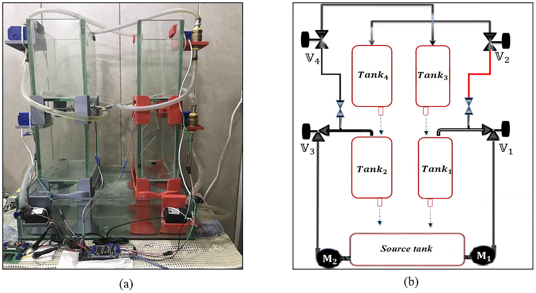
The system of four quadrants: (a) the quadruple system that operates in real-time, (b) the quadruple system’s schematic diagram.
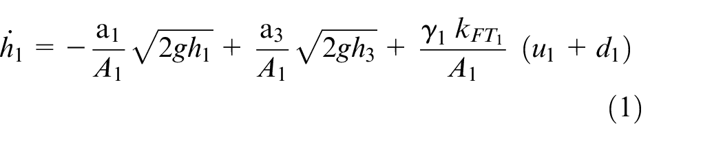
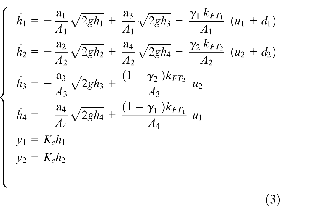
The main objective of a quadruple tank system with nonlinear dynamics is to regulate and track the water levels in two tanks, Tank 1 and Tank 2. These disruptions may be caused by water inputs that were not considered during the design process. A system of nonlinear differential equations can express the dynamics of the water flow:
For Tank 1, the water level
where:
•
•
•
•g is the acceleration due to gravity.
•
•
•
•γ1 is a coefficient related to the valve setting for the flow into Tank 1.
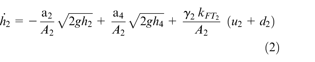
According to this equation, the nonlinearity and complexity of controlling the water level in Tank 1 are further aggravated by interactions between tanks and disturbances external to it. Similarly, considering the particular characteristics and situations impacting Tank 2, we can formulate the differential equation (
Assuming a construction comparable to Tank 1 but modified for its unique circumstances, the differential equation for Tank 2 could take the following generic form:
where:
•
•
•
•g is the acceleration due to gravity.
•
•
•
•γ2 is a coefficient related to the valve setting for the flow into Tank 2.
To accomplish accurate water level control, it is necessary to carefully manage the dynamics peculiar to Tank 2, which are encapsulated in this equation. These dynamics include the impacts of external disturbances and the system’s inherent nonlinear behavior. Where
The system block diagram.
The quadruple H/W implementation
The implemented plant differs from the plant described in 1 in several aspects as follows:
The Motors: In this experiment, a 24 V, 28.8 W, and 1.2 brushless DC motor is used to pump the water with a maximum rate of
Two-way electrical valves: To divide the water delivered from the pump, four 12 V two-way electrical valves, two on each side, are used in this experiment. It was easy to use the three-way valve to distribute the water delivered from the pump to the upper and the lower tanks (i.e.
The Nozzle: To provide a smooth flow, the nozzle shown in Figure 5 is used in the outlet hole of the four-tank. Moreover, this nozzle is available in different diameter sizes, which are (0.6, 0.8, 1, and 1.2 mm). However, the perfect choice of diameter depends on testing how much water flows through it to meet the ideal flow for the experiment’s requirement. In this experiment, the test shows that the nozzle with a diameter (1 and 1.2 mm) provides an appropriate flow of water. Finally, due to the limited time of this work, the nozzle used in this experiment for the quadruple is a 1 mm size.
The Microcontroller: The ARDUINO-MEGA is utilized in this experiment as a microcontroller due to its reliability, low power consumption, ease of use, and fast startup. Thus, the ARDUINO-MEGA with
The sensor: To measure the water level in the two lower tanks, US-100 Ultra Sonic is utilized. The US-100 can measure distances up to 3.5 m; thus, in this experiment, two US-100 are used, one on each side, to measure the water level by the reflected echo on the water surface based on the reflective echo principle. The frame of the utilized Ultra Sonic is shown in Figure 7.
The valve’s motor driver shield: In this experiment, an L293D motor driver shield is used to control the DC motor of the valve mentioned previously. The L239D motor driver consists of four H-bridges; each one provides 0.6 A to each motor. To maintain the speed of the DC motor of the four valves, the L2393D is interfaced with the ARDUINO-MEGA to provide accurate control of the valve motor. Also, it is essential to note that the L293D can control four DC motors, two stepper motors, and two servo motors. Because of that, the L239D is utilized in this experiment as the valve motor driver. The actual frame of the L239D is shown in Figure 8.
Also, a power supply of 24 V and 17A DC supply is used to supply the power required to run the main motors (

The DC 24 V
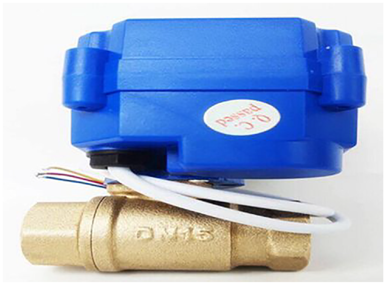
12 V two-way valve.
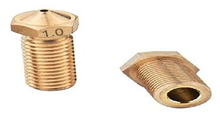
The 1 mm size nozzle.
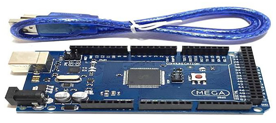
The microcontroller (ARDUINO-MEGA).
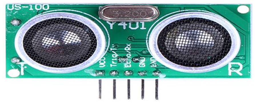
The US-100 ultra sonic sensor.
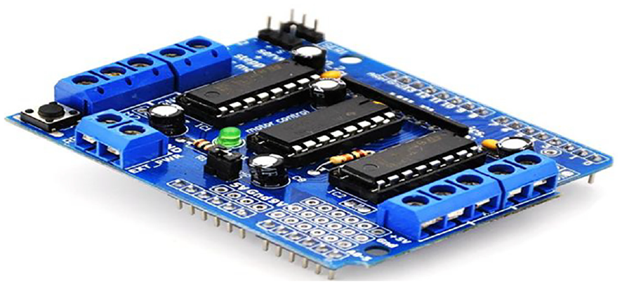
The L239D motor driver shield.
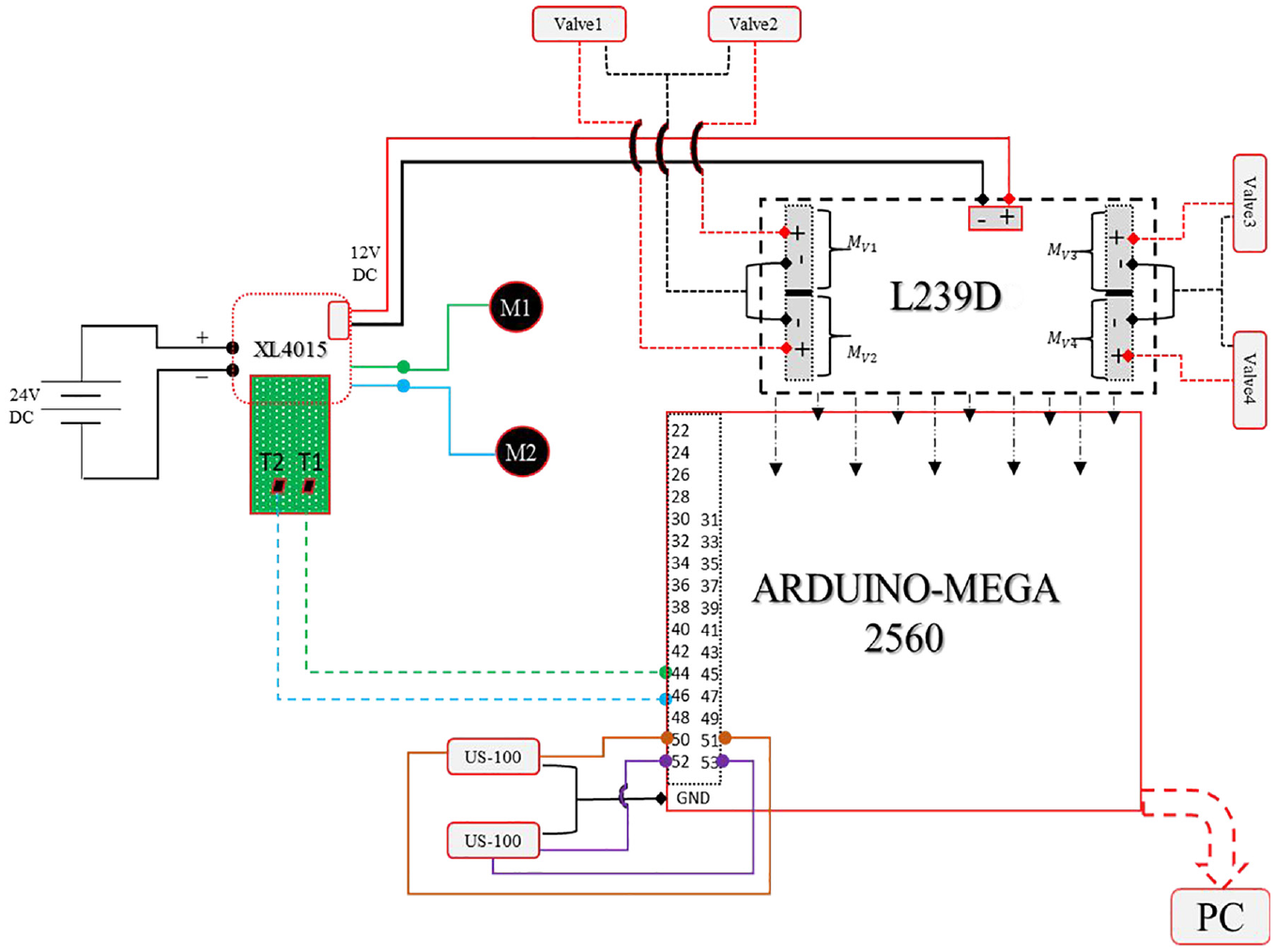
The complete circuit diagram.
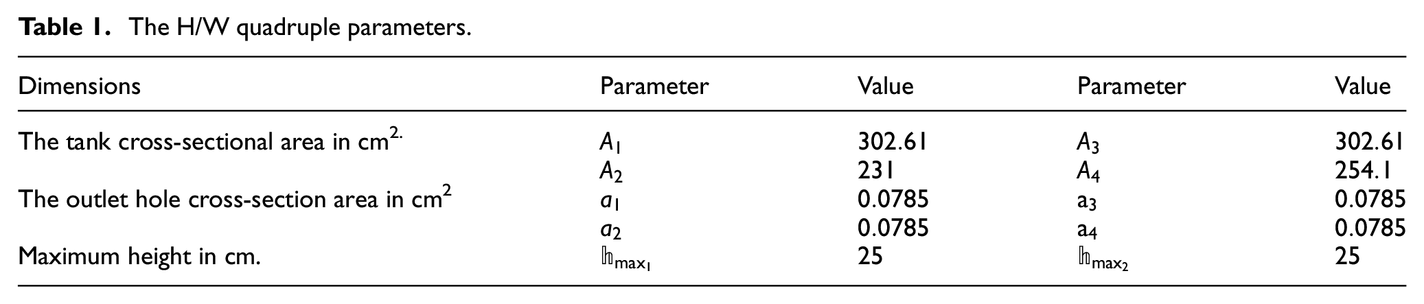
The H/W quadruple parameters.
The proposed control technique
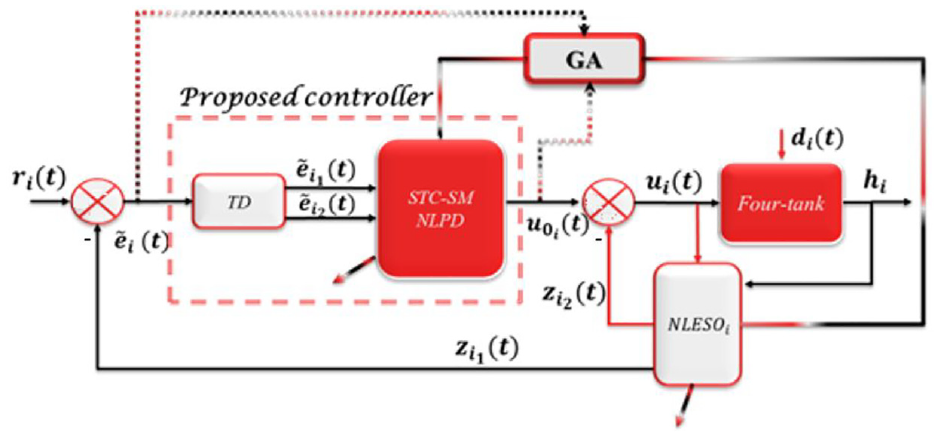
This paper proposes the use of the Active Disturbance Rejection Control (ADRC) method. Initially suggested in late 1989 by, 13 ADRC is a practical approach to control systems. A classical ADRC configuration consists of three primary components: the tracking differentiator (TD), the extended state observer (ESO), and the state error feedback (SEF). The design of the ADRC is tailored according to the system’s relative degree. For instance, based on the mathematical model of the quadruple process cited in, 1 the relative degree of the quadruple system is ρ = 1.
where
Therefore, two ADRCs are needed, one for the first .sub-system and the other for the second sub-system.
The proposed TD
In contrast to the traditional differentiator, the TD is in charge of accurately responding to the original and derivative signals by taking into account their smoothness. The dynamics of the suggested TD is described as:
where
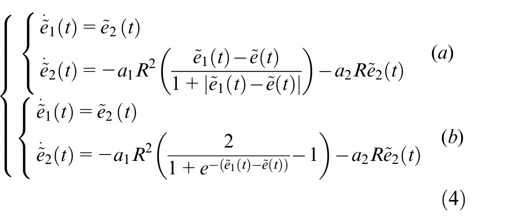
The suggested nonlinear controller
The following is an expression of the two nonlinear controllers suggested in this study:
The suggested nonlinear extended state observer (NNLESO)
Two nonlinear controllers have been developed in this study, and their expressions are as follows:
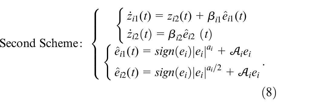
where
We use the quadruple system H/W platform to see how the proposed method performs in real-world scenarios. Theoretically, the output of the tanks is the measured level of the water. However, in this experiment, the output will be expressed as follows:

Where
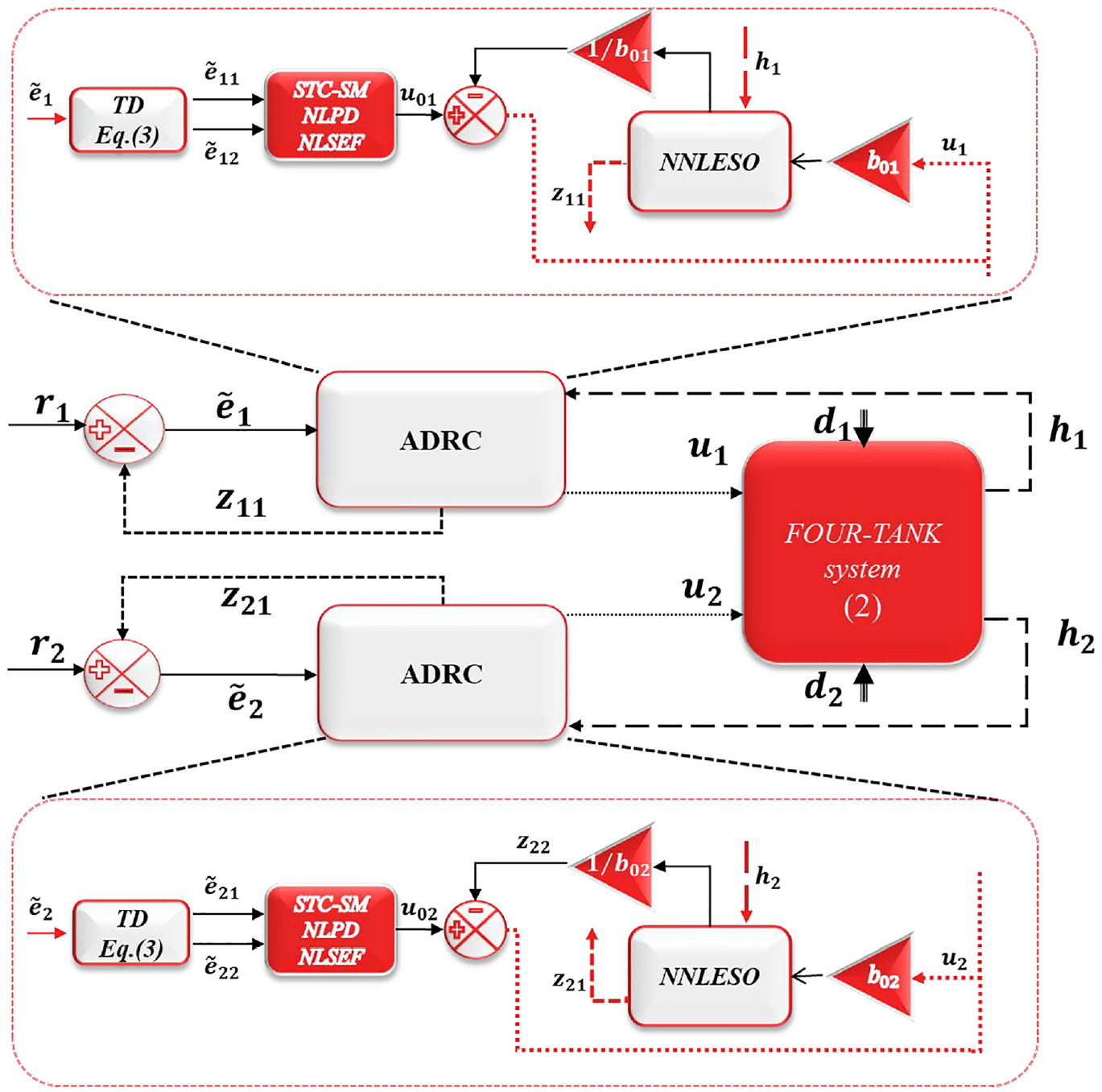
The complete controlled system.
Simulations and experimental results
This section will present the experimental results of the quadruple system in the presence of exogenous disturbances, utilizing the various methods of the modified ADRC discussed earlier. The complete hardware (H/W) implementation platform is depicted in Figure 11. Additionally, the parameters for the five controller and observer schemes are detailed in Appendix 1, Tables A.1–A.6. In this experiment, a single test involving an exogenous disturbance is applied to the system. The impact of this disturbance on the H/W implementation is illustrated subsequently. The experimental results are compared with simulated results, which are presented last. Initially, the reference water levels are set to 15 cm for
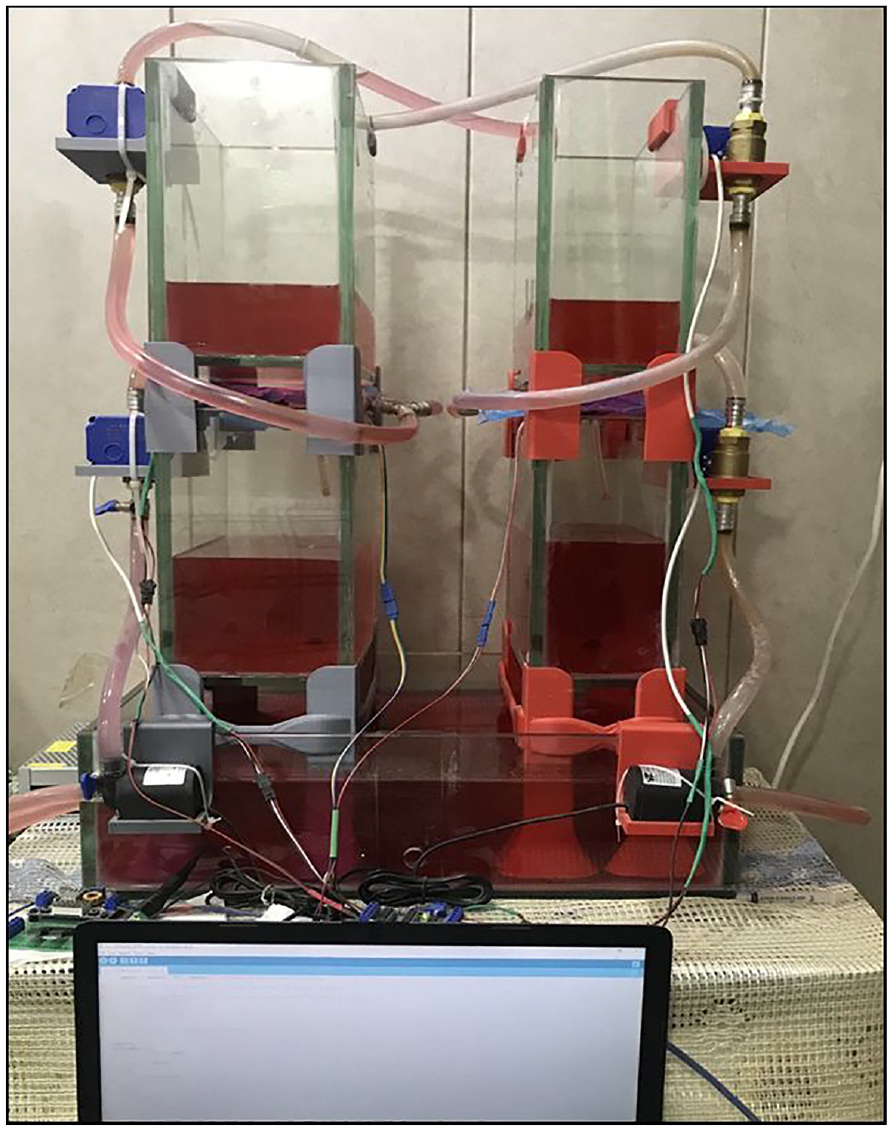
The complete quadruple system (the H/W implementation).
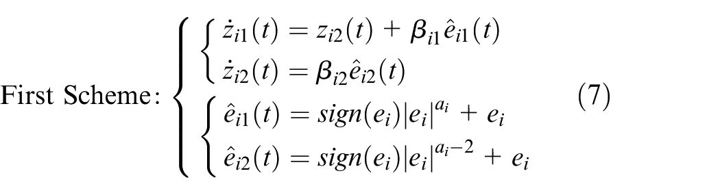
First scheme: The IADRC-TD
Figure 12(a) and (b) depict the output responses of the first and second subsystems utilizing IADRC-TD, respectively. Additionally, the control signals for both subsystems are shown in Figure 12(c) and (d). As observed in Figure 12(a), the addition of water to the first tank increases the amplitude of the output response for approximately 1.5 s, demonstrating the effectiveness of the proposed technique in managing the applied disturbance. It is important to note that the response does not start from zero due to two reasons: firstly, the tank design maintains a minimal water level, typically less than 0.001 cm, and secondly, there is a delay before the ultrasonic sensor begins to detect water, even if the tank were empty. Figure 12(b) shows that the proposed method quickly mitigates the disturbance and returns the system to its steady state within about 1 s. Figure 12(c) and (d) illustrate the control signals for both subsystems, highlighting the fluctuations caused by the disturbance.
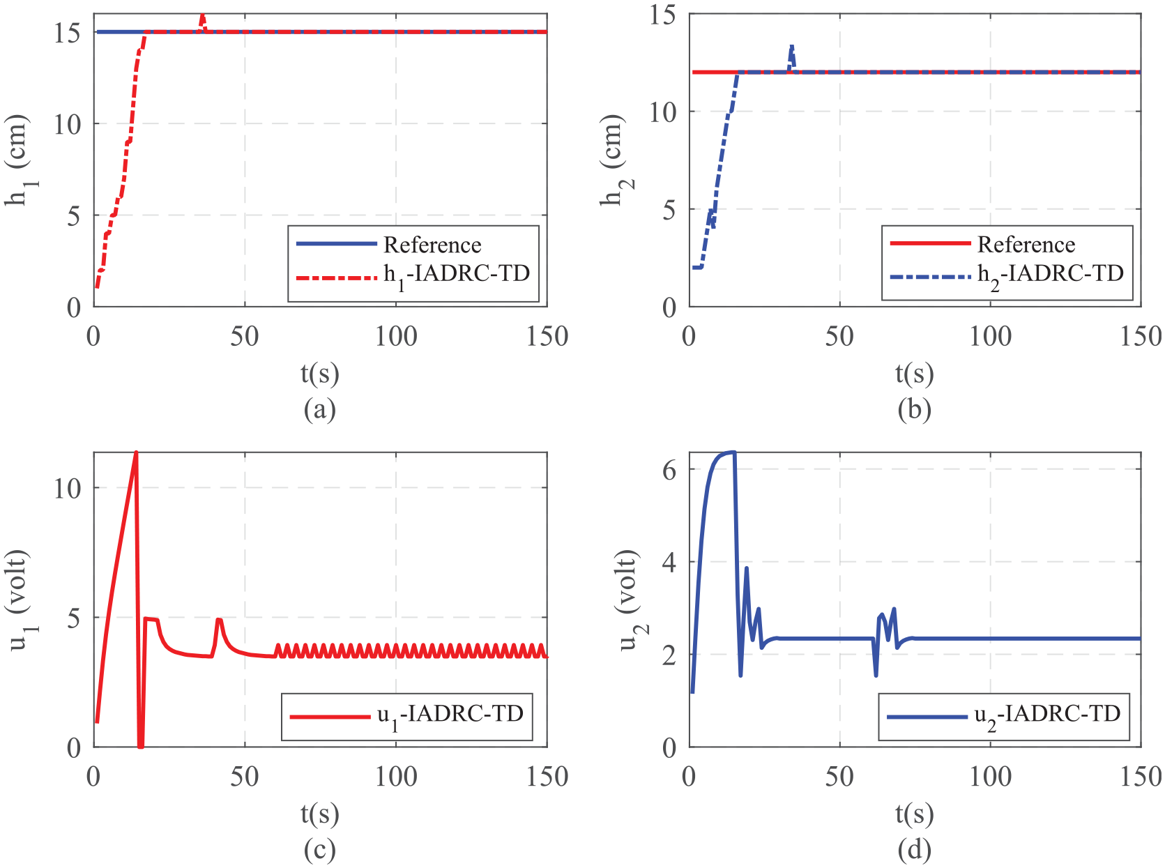
The output response using IADRC-TD: (a) the water level of
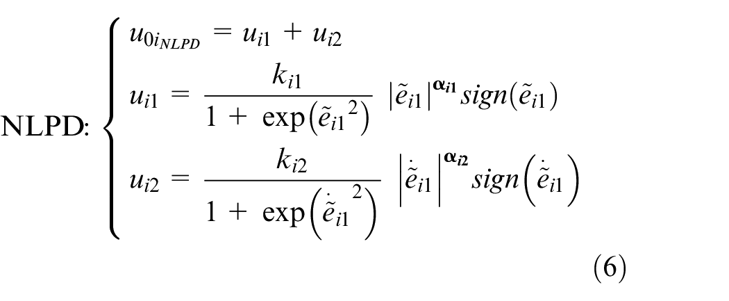
Second scheme: The NLPD-ADRC
Figure 13(a) and (b) showcase the output responses of the two subsystems. Thanks to the well-defined controller and observer, the output response smoothly follows the target value. Specifically, the output response in Figure 13(a) increased by 4.666% of the steady-state value and remained elevated for approximately 2 s after the disturbance ceased, before returning to steady state. Meanwhile, the output response in Figure 13(b) stayed constant for almost 2 s before rising by 8.333% of the steady-state value. The control signals for both subsystems are illustrated in Figure 13(c) and (d). Notably, the control signal chattering, as displayed in these figures, is caused by the rapid voltage changes.
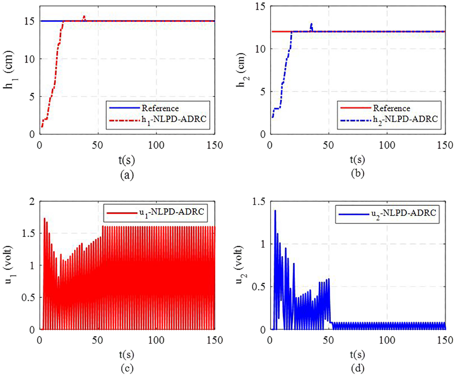
The output response using NLPD-ADRC: (a) the water level of
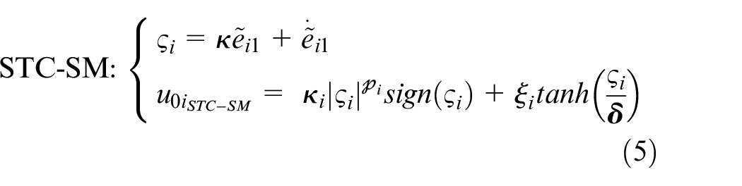
Third scheme: The STC-ADRC
Figure 14(a) and (b) depict the responses of the two subsystems to the output. The suggested technique reached a steady state and accurately tracked the target value after approximately 20 s. The output response in Figure 14(a) returned to its equilibrium level about 2 s after the disturbance ceased, having increased by 3.33% from its steady-state value. Similarly, the output response in Figure 14(b) increased by 4.16% and returned to the equilibrium value after approximately 2 s. Figure 14(c) and (d) display the control signals for both subsystems. A brief voltage spike is evident when the motor starts, as shown in these figures. The proposed method effectively reduced chattering and maintained control signal stability. Notably, the control signal dropped to nearly zero when the water level exceeded the target level but increased again as the designed observer efficiently attenuated the disturbance.
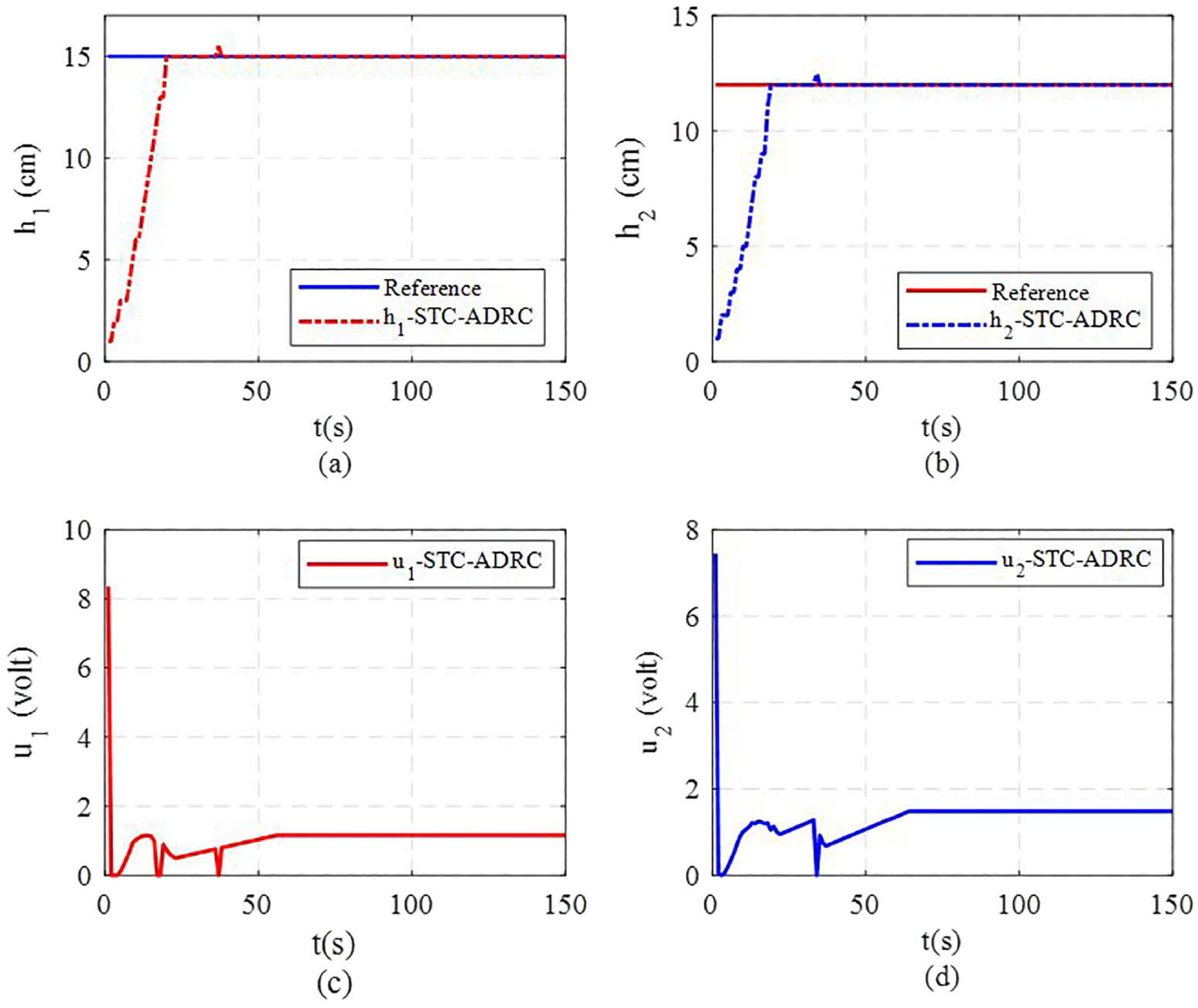
The output response using STC-ADRC: (a) water level of
Fourth scheme: The Sfal-ADRC
Figure 15(a) and (b) illustrate the water levels for the two subsystems. Figure 15(a) demonstrates that the disturbance affects the output response for approximately 2 s, causing it to overshoot the steady state by 6.66%. Additionally, the output response of the second subsystem, shown in Figure 15(b), is impacted by the disturbance for about 10 s, deviating 14.285% from the steady state. Figure 15(c) and (d) display the control signals for the two subsystems. The control signals begin to fluctuate around 2 s after the disturbance is applied.
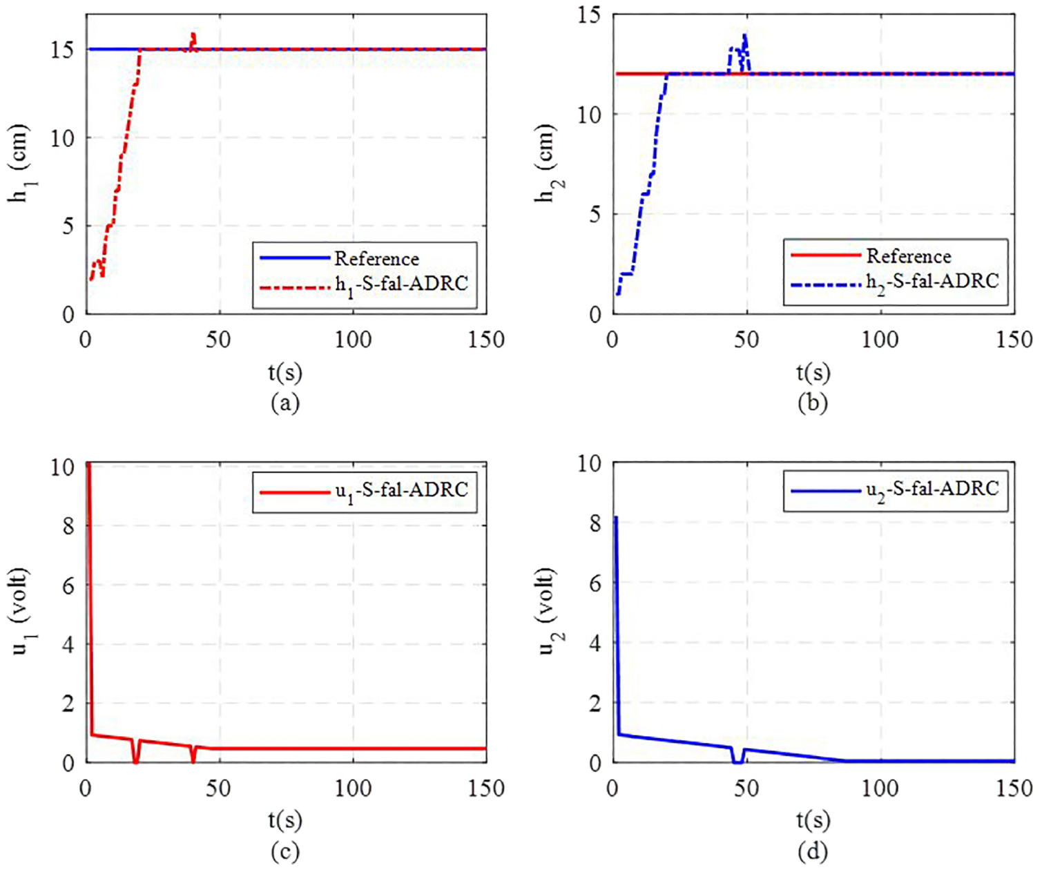
The output response using Sfal-ADRC: (a) water level of
Fifth scheme: The Dfal-ADRC
Figure 16(a) and (b) display the water levels of both subsystems. As depicted in Figure 16(a), the output response is affected by the disturbance for approximately 3 s, experiencing a 2% overshoot and a 0.666% undershoot from the steady state. Furthermore, Figure 16(b) shows that the output response of the second subsystem is impacted for about 2.5 s, resulting in a 6.666% overshoot from the steady state. Despite these disturbances, the technique performed admirably in tracking the required value. Figure 16(c) and (d) collectively show the control signals for the two subsystems. According to the data, the control signal experienced numerous fluctuations within a specific time frame, indicating that the disturbance impacted it for around 26 s.
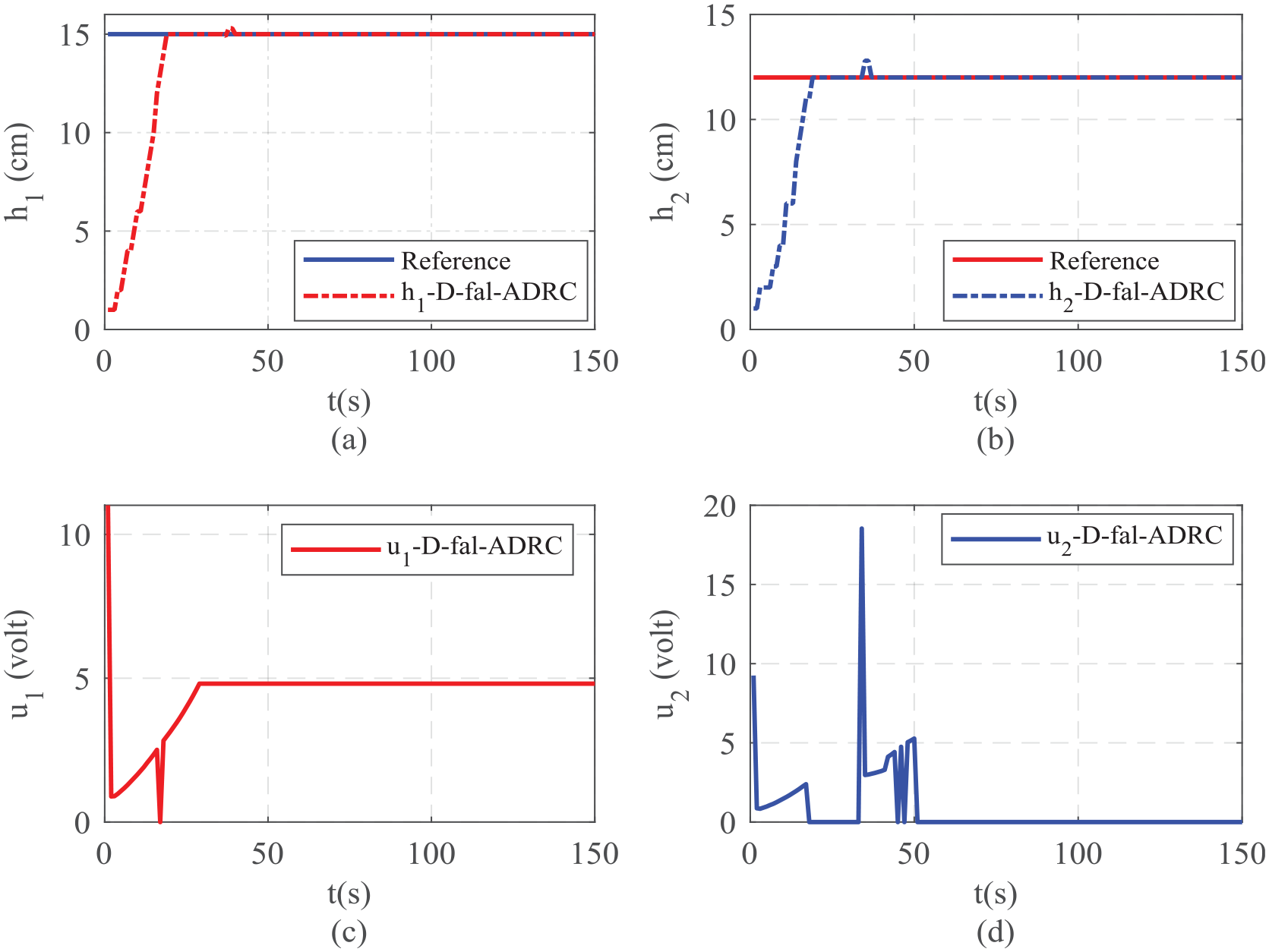
The output response using Dfal-ADRC: (a) the water level of
Figure 17(a) displays the water level of Tank1 for all the schemes previously mentioned. It shows that the IADRC-TD response reaches the steady state nearly faster than the other schemes. Both the NLPD-ADRC and STC-ADRC demonstrate fewer fluctuations in the output response, with deviations of 3.33% and 4.666% from the equilibrium value, respectively. Figure 17(b) depicts the water level of Tank for all the schemes. The figure illustrates that the response of all schemes is nearly identical with good performance, although the Sfal-ADRC is significantly affected by the disturbance. Figure 18(a) and (b) present the control signals for both subsystems. Notably, the last two schemes, STC-ADRC and Dfal-ADRC, outperform the others in terms of chattering reduction and energy efficiency.
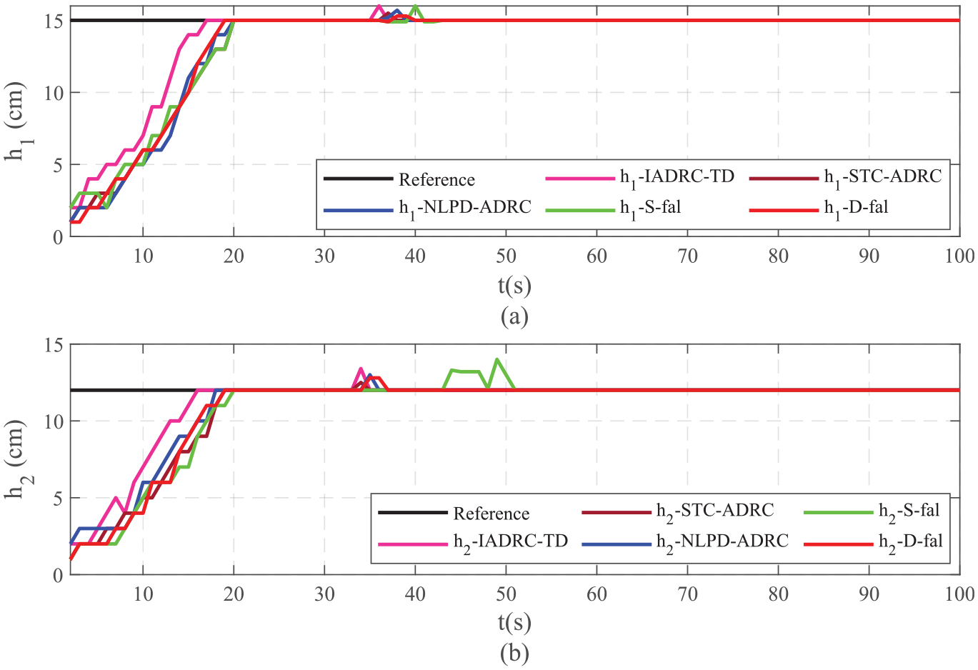
The output response: (a) water level of
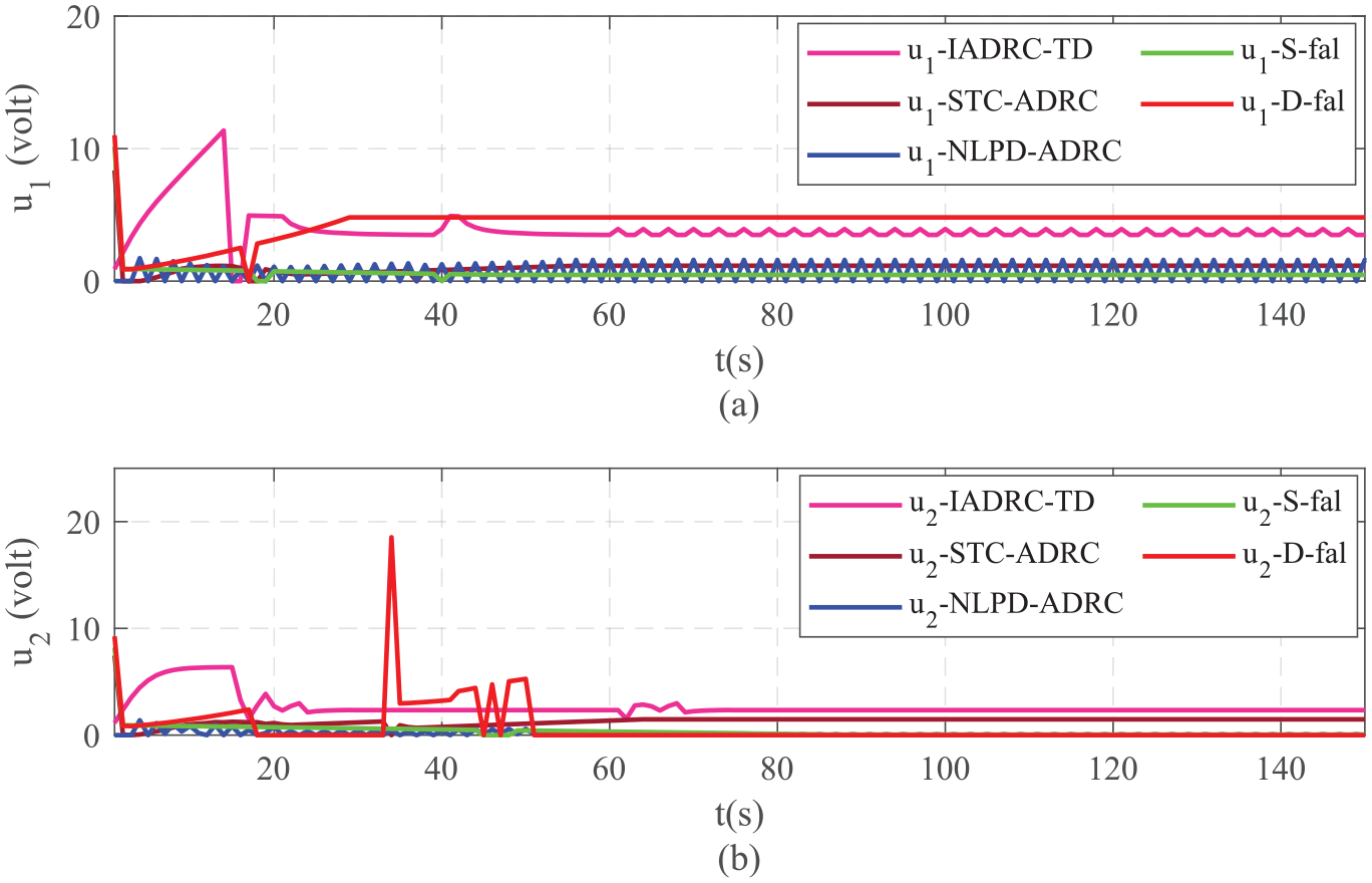
The control signal: (a) the control signal of first sub-system, (b) the control signal of second sub-system.
Conclusions
This paper has introduced the control of the hardware (H/W) implementation of the quadruple system using the anti-disturbance algorithm represented by ADRC, under the effect of exogenous disturbances. The experimental results, as illustrated by the figures previously mentioned, are excellent. Although the control signal exhibits chattering in some of the utilized methods, the proposed modified ADRC (STC-ADRC) consistently delivers better results. Furthermore, other schemes of the PMADRC, such as IADRC-TD and NLPD-ADRC, also perform well in several aspects, notably in quickly reaching the steady state value and effectively attenuating disturbances.
Footnotes
Appendix 1
This appendix contains the mathematical representation of the methods used in comparison with PMADRC, in addition to the values of the parameters of all methods utilized in this work.
Appendix 2
This appendix contains the Puecdo-code Algorithms used in this experiment for of all methods utilized in this work.
The pseudo-code of the distance measured by the ultrasonic for both sub-systems is listed in
Declaration of conflicting interests
The author(s) declared no potential conflicts of interest with respect to the research, authorship, and/or publication of this article.
Funding
The author(s) received no financial support for the research, authorship, and/or publication of this article.
Research data availability
“Data sharing is not applicable to this article as no datasets were generated or analyzed during the current study.”