
Abstract
Conventional sliding mode control (SMO) utilizes a sign function and a low-pass filter (LPF) to achieve sensorless control of a permanent magnet synchronous motor (PMSM). However, the introduction of the sign function generates a large number of high harmonics, resulting in a significant system output chattering, whereas the addition of the LPF generates control delays and phase shifts. These degrade the PMSM speed and the position estimation accuracy and reduce the system control performance. To improve the performance of the PMSM, adaptive quasi-proportional resonant sensorless control with parameter estimation (AQPR_PE) is proposed. In this control model, an adaptive quasi-proportional resonance controller is used reduce the system output error and to weaken the chattering phenomenon. Meanwhile, the system PMSM parameters are estimated online and fed back to the control model to improve the system parameter robustness and the control accuracy. The Bode diagram, Popov theory, and root trajectory are used to analyze the stability of AQPR, parameter estimation, and AQPR_PE, respectively. Finally, the effectiveness of the proposed method is demonstrated by experimental validation.
Keywords
Introduction
Permanent magnet synchronous motors (PMSMs) are widely used in daily life because of their advantages of the simple structure, small size, and low manufacturing cost. 1 In order to realize excellent control performance of a PMSM, the speed and position of the motor needs to be accurately obtained. In the traditional position detection method, mechanical sensors such as electronic or electromechanical sensors are used for direct measurements; for example, as Hall effect devices, resolvers, and optical type encoders.2,3
However, the installation of these mechanical sensors increases the size, volume, and weight of the system, which seriously limits the miniaturization of the motor. At the same time, some sensors have strict requirements on the operating environment because it greatly affects the measurement accuracy. The increase in the number of wiring of electrical components will reduce the anti-interference performance.4–6 Therefore, sensorless control research of PMSMs has received extensive attention, and many control methods have been proposed: for example, extended back-electromotive force method (EMF),7,8 magnetic chain observation method,9,10 extended Kalman filter method,11,12 and high-frequency signal injection method.13,14 Among them, the EMF method is simple and reliable and is widely used in high- and medium-speed situations. The main EMF-based control methods are sliding mode control,3,15–21 state observer,22,23 and model reference adaptive control,24,25 model predictive control.26–28 As sliding mode control does not require high system model accuracy, is insensitive to parameter changes and external disturbances, and is a special nonlinear control system with a variable structure, it can be used to estimate the EMF and extract the speed and position information in the EMF. As per the literature Sun et al., 26 a sensorless control method based on finite position set model predictive control is proposed. SMO replaces PI method in the speed loop, and the duty-cycle model predictive control is used to improve the dynamic and static stability performance, and the reference voltage is obtained based on the deadbeat principle. The experimental results show that the proposed method greatly reduces the amount of calculation and can accurately obtain the information of rotor position and speed. As per the literature Ding et al., 15 at high and medium speeds, low switching frequency cycles are close to the resonance point, triggering resonance phenomena that decrease the motor speed and the position estimation performance. To solve this problem, an accurate discrete sliding mode control (SMO) based on adaptive filters was proposed. The results showed that the method could improve the speed and the position estimation accuracy and enhance the robustness of the system against uncertainty disturbances. In a previous study, 27 a new modulator-free finite-control-set model predictive current control (FCS-MPCC) is proposed, which combined virtual vector with duty-cycle to avoid modulators, reduce the complexity of the model, improve the accuracy of voltage selection, and reduce current harmonics. At the same time, the optimal reference voltage is determined based on the deadbeat principle. Compared with conventional MPCC and duty-cycle MPCC, it has faster dynamic response characteristics and better steady-state performance. The nonlinearity of the inverter and the spatial harmonics of the flux linkage lead to inaccurate EMF estimation and trigger rotor position harmonic fluctuations. To address this problem, in a previous study, 18 a bilinear recursive least squares adaptive filter was proposed and integrated into an SMO controller. The controller suppressed the harmonic components and compensated for the fluctuations caused by the inverter nonlinearity and the flux linkage space harmonics under different steady-state and dynamic conditions. Experiments showed that the method could improve the position estimation accuracy and enhance the robustness of the controller.
However, the sign function introduced by the SMO-based sensorless control method deteriorated the system output and intensified the high-frequency chattering phenomenon. The low-pass filter (LPF) generated phase shift while filtering out the high-frequency signal, increasing the system output error and decreasing the control accuracy. In order to solve the problems above and to improve the PMSM control, in a previous study, 19 SMO and PLL were combined based on the conventional SMO principle. In order to reduce high-frequency chattering, a switching function with a double boundary layer structure was used instead of the traditional sign function, and the PLL was used to extract the position information. The experimental results showed that the method had good tracking performance. In a previous study, 3 an adaptive frequency second-order interference observer was established to estimate the magnetic chain and EMF. This eliminated the requirement of phase delay compensation for estimating the EMF by conventional SMO and reduced the position estimation error. The experimental results verified that the proposed method could guarantee excellent sensorless control performance. Owing to the low-order harmonic components, magnetic field saturation, and DC bias, the EMF information extracted by the conventional LPF was not accurate, resulting in low position estimation accuracy and significant phase delays. To solve this problem, a previous study 20 proposed the sliding mode control of a dual second-order generalized integrator phase-locked loop to eliminate the harmonic components in the EMF estimates and to perform delay compensation in order to improve the dynamic response speed and the control accuracy. Regarding the high-frequency chattering of conventional SMO and the lack of finite-time convergence, a previous study 21 proposed a high-order sliding-mode control law to suppress the high-frequency chattering and designed the terminal sliding-mode surface to achieve finite-time convergence. The method was experimentally demonstrated to have high estimation accuracy under the condition of guaranteed robustness.
To improve the speed and position estimation performance of a PMSM under sensorless control, this paper proposes an adaptive quasi-proportional resonant sensorless control method with parameter estimation. The main contributions of the paper are as follows:
The AQPR controller is introduced to solve the problems in SMO, such as obvious output chattering due to the introduction of a large number of high harmonics generated by the symbolic function, and the control delay and phase shift caused by the low-pass filter. The system output error is reduced, the chattering phenomenon is weakened, and the control performance is ensured under different carrier ratios.
The PE controller was established to estimate PMSM system parameters online in real time and feed back to the AQPR controller, which enhanced the robustness of the system to parameter changes and improved the detection accuracy of the rotor position and speed.
By using Bode diagram, Popov theory and root locus method, the stability analysis of a AQPR controller, PE controller and AQPR_PE model is carried out respectively.
The paper is organized as follows. Section II introduces the conventional PLL-based SMO method. Section III describes the adaptive quasi-proportional resonant sensorless control with parameter estimation (AQPR_PE) model. Section IV analyzes the AQPR and parameter estimation. Section V discusses the stability analysis of the AQPR_PE model. Section VI discusses experimental verification; Section VII concludes the paper; and Appendix A section shows the stability proof of parameter estimation according to Popov stability theory.
Conventional PLL-based SMO method
The mathematical model of the PMSM in the stationary coordinate system can be expressed as
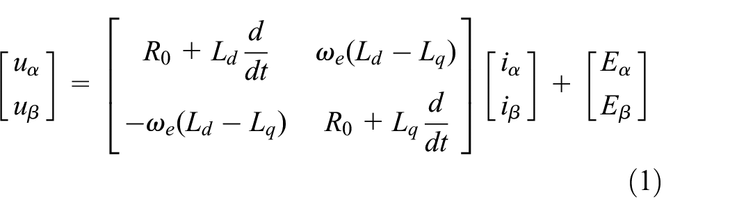
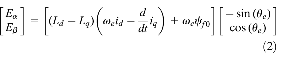
where [uα, uβ]T denotes the voltage in the α–β axis of the stationary coordinate system, [iα, iβ]T– the current in the α-β axis, R0– the stator resistance, ωe– the electrical angular velocity, θe– the rotor position angle, and Ld and Lq are the stator inductances. For the surface-mounted PMSM, Ld = Lq = L0. ψf0– the permanent magnet flux linkage, and [Eα, Eβ]T– the EMFs.
From equation (2), it can be seen that the EMF contains the speed and rotor position information, so the speed and rotor position can be solved as long as the EMF is accurately observed. Therefore, the SMO method is used to obtain the EMF, and to facilitate the SMO model, Equation (2) is converted into the current state equation of equation (3):

Using [iα, iβ]T in equation (3) as the variables of the state equation and [uα, uβ]T as the system inputs, the sliding mode observation function of equation (4) is established:

Where
Subtracting equation (4) from equation (3) gives the stator current error:

Here, [Δiα, Δiβ ]T denotes the current error.
The slip control rate is designed as shown in equation (6):

In this equation, k denotes the sliding mode controller gain parameter, and sgn (-) denotes the sign function. For eventual convergence of the current error, according to the sliding mode surface arrival function condition,

Therefore, the gain k needs to satisfy

The conventional SMO model uses the sign function as the sliding mode surface switching function, which can lead to a large number of high harmonics in the output and cause chattering. To reduce chattering, an LPF is connected after the sign function. When the state variables converge to the sliding mode plane, that is, Δiα = 0, Δiβ = 0, equation (9) can be obtained:

Here,
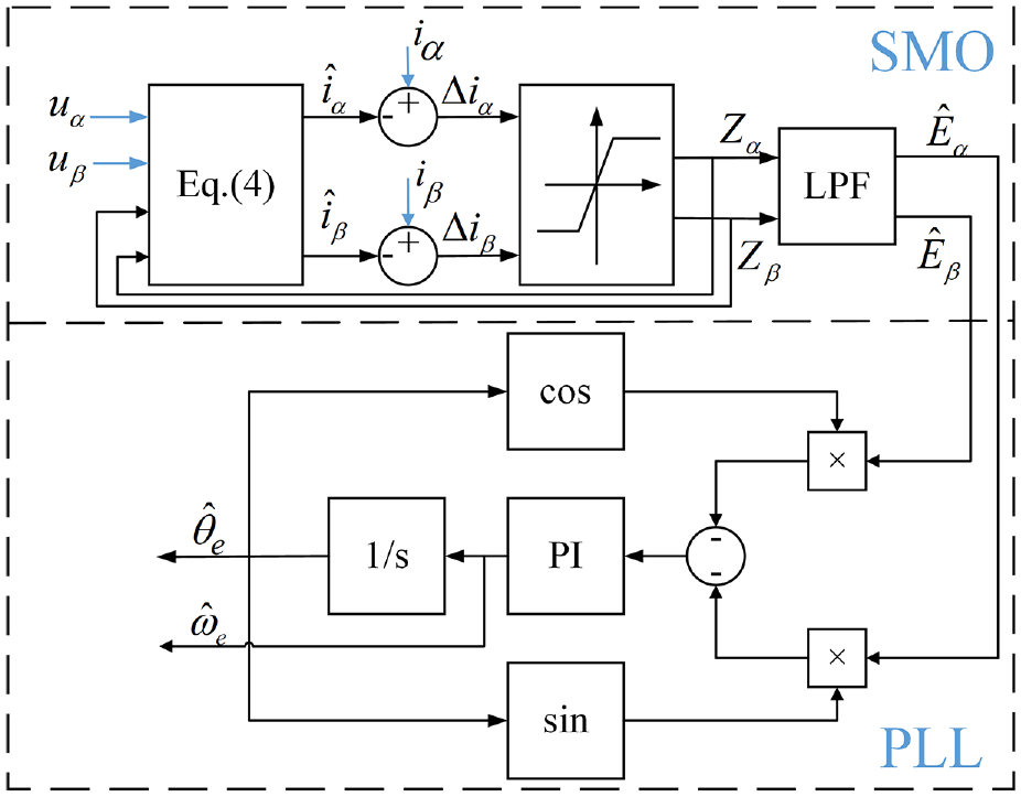
The sensorless control structure of PLL-based SMO.
Figure 2 shows the simulation analysis of total harmonic distortion (THD) of PLL-based SMO under different carrier ratios. In the simulation, PMSM speed was set as 600 rpm, base frequency as 40 Hz, and switching frequency as 10 and 1 kHz, respectively. As shown in Figure 2, when the switching frequency drops from 10 to 1 kHz, the THD of current in PLL-based SMO method increases from 36.74% to 244.31%, resulting in serious current distortion, obvious chattering phenomenon and reduced estimated performance.
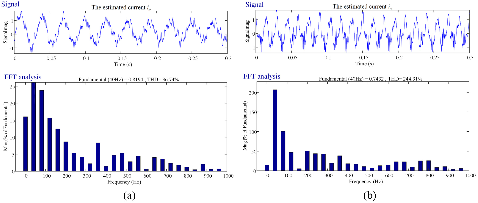
Simulation analysis of THD of PLL-based SMO controller under different carrier ratios: (a) high carrier ratio and (b) low carrier ratio.
Adaptive quasi-proportional resonant sensorless control with parameter estimation
The conventional SMO method uses the sign function for the quick system convergence to the sliding mode plane, but the introduction of the sign function leads to the generation of a large number of high harmonics, which causes significant system output chattering. Meanwhile, the addition of an LPF generates control delay and phase shift. When the fundamental frequency is close to the switching frequency, the filtering effect is reduced, which affects the system control accuracy. Therefore, in this paper, AQPR is used to reduce the system output chattering and improve the tracking accuracy. At the same time, the PMSM parameters in the control model are estimated online for the control model and fed back to the AQPR controller to improve the robustness of the system parameters.
From equation (3), equation (10) is obtained:
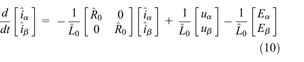
Here,
After transforming the time-domain equation of state of equation (10) into the S-domain equation of state, 29 we obtain

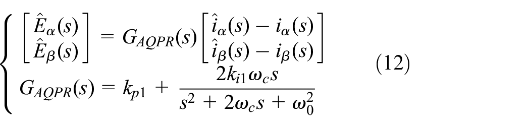
Here, kp1 and ki1 denote the gain parameter, ωc denotes the bandwidth, and ω0 denotes the resonant frequency.
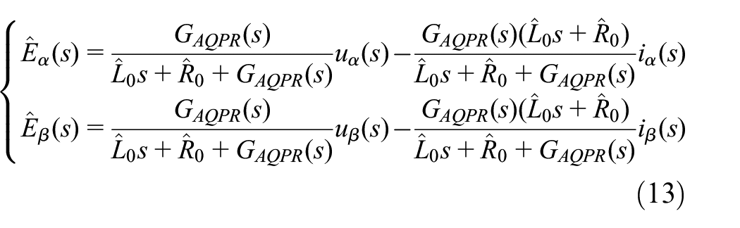
Replace the Eα and Eβ in equation (11) with
The current error equation of equation (14) is obtained by subtracting equation (3) from equation (10), and equations (15) and (16) represent the internal variable expressions.


According to Popov’s super-stability theory, equation (17) is obtained, and the system stability is sought in detail in the Appendix section.

Here, γ12 denotes any finite positive number.
The adaptive regulation law for parameter estimation is chosen as the proportional integral form of equation (18), and equation (19) represents the internal variable expressions. 30


Substituting equation (19) into equation (18) yields Equation (20).

Similarly, inductance parameters can be estimated as equation (21):

Here, kp2 and ki2 are the gain parameters. The stator resistance and inductance estimated by Equations (20) and (21) are fed back to equation (13). Figure 3 shows the relationship between resistance, inductance changes and current errors. As shown in Figure 3, both resistance and inductance change affect the α-β axis current. Figure 4 represents the AQPR_PE model structure diagram.

The relationship between resistance, inductance changes and current errors.

The AQPR_PE model structure diagram.
Figure 5 shows the simulation analysis of THD of AQPR_PE controller under different carrier ratios. In the simulation, PMSM speed was set as 600 rpm, base frequency as 40Hz, and switching frequency as 10 and 1 kHz respectively. As can be seen from Figure 5, when the switching frequency drops from 10 to 1 kHz, the THD of AQPR_PE controller increases from 24.73% to 37.00%, and THD changes little. Under different carrier ratios, no serious distortion occurs and current chattering phenomenon is not obvious, which still maintains a better estimation performance.
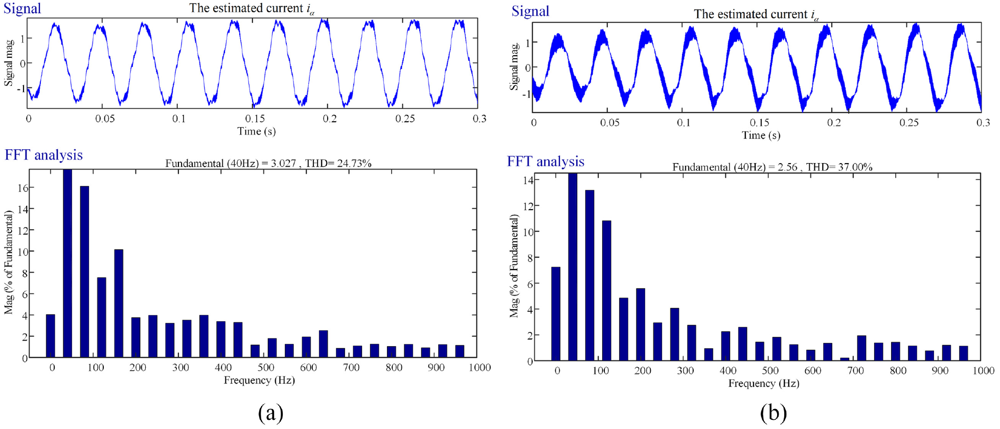
Simulation analysis of THD of AQPR_PE controller under different carrier ratios: (a) high carrier ratio and (b) low carrier ratio.
AQPR Controller and Parameter Estimation Analysis
From equation (12), it can be seen that AQPR contains three parameters: kp1, ki1, and ωc. Figure 6 represents the Bode plot analysis of the effect of the parameter variations on the controller. Figure 6(a) is the Bode plot when ω0 = 251 rad/s, the bandwidth ωc is 2.51 rad/s, ki1 is 10, and kp1 is 0.5, 1, and 1.5. As kp1 is increased, the amplitude beyond the mid-band rises accordingly, but that at the resonant frequency remains the same, which indicates that kp1 has little effect on the resonance. Normally, the value of kp1 should be >1 to suppress harmonics. Figure 6(b) shows the Bode plot at a resonant frequency ω0 of 251 rad/s, a bandwidth ωc of 2.51 rad/s, kp1 of 0.5, and ki1 following the order of 5, 10 and 20. As ki1 increases, the amplitude increases at the resonant frequency, revealing the effect of ki1 in reducing steady-state errors. However, with the increase of ki1, the frequency band range becomes larger, and the influence of useless signals is enlarged, which is not conducive to system stability. Figure 6(c) shows the Bode plot for ω0 = 251 rad/s, kp1 = 0.5, ki1 = 10, and bandwidth ωc varying from 2.51 rad/s to 5.02 rad/s and 7.53 rad/s in order. As ωc is decreased, the amplitude is almost constant at the resonant frequency, the bandwidth becomes smaller accordingly, and the frequency domain selectivity becomes better. However, the dynamic response of the system becomes slower. Therefore, for a better control of AQPR, ki1 is adjusted to reduce steady-state errors, and ωc is regulated to suppress the influence caused by frequency fluctuations.
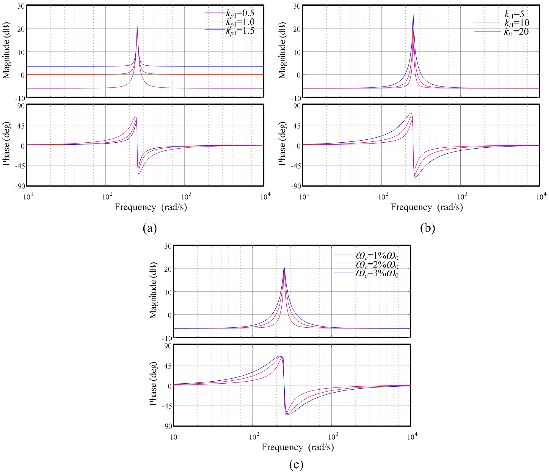
The Bode plot analysis of the effect of the parameter variations on the controller: (a) kp1, (b) ki1, and (c) ωc..
Figure 7 represents the simulation results of the parameter estimation. In the simulations, the PMSM rotational speed was set to 1000 rpm, the initial resistance R0 was 2.84 Ω, and the inductance L0 was 8.5 mH. In order to verify the convergence speed and the tracking accuracy of the parameter estimation method, the resistance and the inductance were increased twice at 0.1 s and restored to the values at the initial moment at 0.3 s. As can be seen from Figure 7, the tracking accuracy of the parameter estimation is high, and the given value can be stably tracked even in the steady state. In the dynamic process where the parameters vary, the parameter estimation can track the changes quickly and converge to the actual values with a fast dynamic response.

The simulation results of the parameter estimation: (a) stator resistance and (b) stator inductance.
Stability analysis of the AQPR_PE system
According to equation (13), the closed-loop transfer function of the EMF is found:

The EMF open-loop transfer function is found by combining equations (12) and (22) according to the control principle 30 :
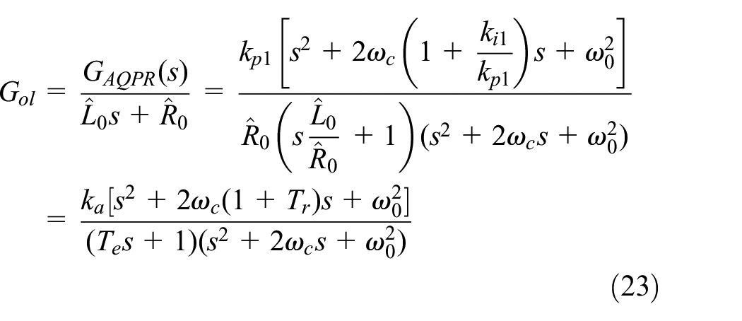
where
By considering the one-beat delay of the control system and using a bilinear transformation to convert the transfer function in the continuous time domain into a discrete-time system by mapping the S-plane to the unit circle in the Z-plane, equation (24) is obtained:
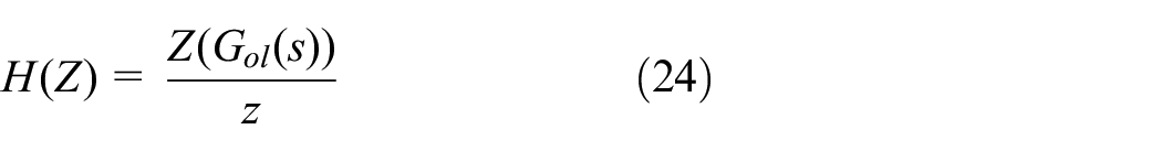
where z denotes the discrete operator.
Figure 8 represents the root trajectory of the control system in the discrete state. In Figure 8(a), the system is in stability when Te = Tr = 15 ms, and the gain parameter ka increases gradually with speed, choosing the appropriate gain parameter so that the characteristic root of the controller lies inside the unit circle. In Figure 8(b), different electrical time constants are obtained by varying the induction and the resistance. The change in electrical constant has little effect on the gain parameters. In Figure 8(c), the gain parameter ka decreases with the increase of Tr at a speed of 1000 rpm. According to the root trajectory and the unit circle focus in Figure 8, the critical gain parameter is obtained, and the appropriate gain parameter is selected so that the root trajectory is within the unit circle, when the system is in a stable state.

The root trajectory of the control system in the discrete state: (a) the speed changes, (b) Te changes, and (c) Tr changes.
Experiment validation analysis
In order to verify the effectiveness of the proposed method, experiments were conducted on the PMSM platform, as shown in Figure 9. The platform adopts MATLAB/Simulink for the algorithm model design of the servo system. When the control algorithm is built, the target code is compiled, generated, and downloaded to the target machine through the developed software. The target machine controls the servo PMSM through a dedicated control card and the loaded PMSM through a motion control card. Table 1 shows the PMSM parameters. Figure 10 shows the experimental block diagram of the PMSM drive and control system

The PMSM experimental platform.
PMSM system and control parameters.


The experimental block diagram of the PMSM drive and control system.
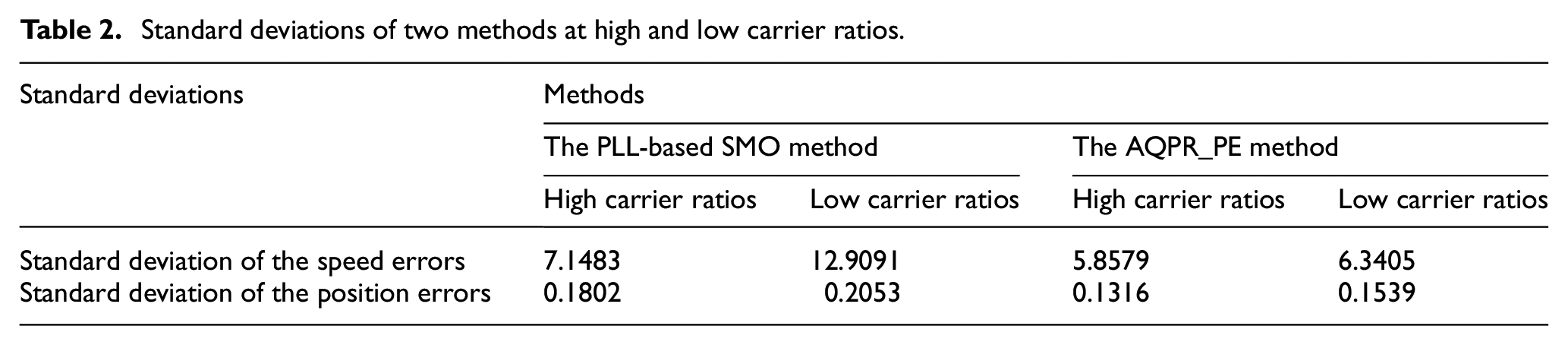
In order to verify the control performance of the AQPR-PI method under low carrier ratios, the method proposed herein was compared with the PLL-based SMO method. The PMSM rotational speed was set to 500 rpm and the switching frequency – to 10 and 1 kHz. The corresponding carrier ratios were 300 and 30. Figures 11 and 12 shows the experimental results of the PLL-based SMO method at high and low carrier ratios, respectively. Figures 13 and 14 represent the experimental results of the AQPR_PE method at high and low carrier ratios, respectively. Table 2 shows the standard deviations of the two methods at high and low carrier rates.

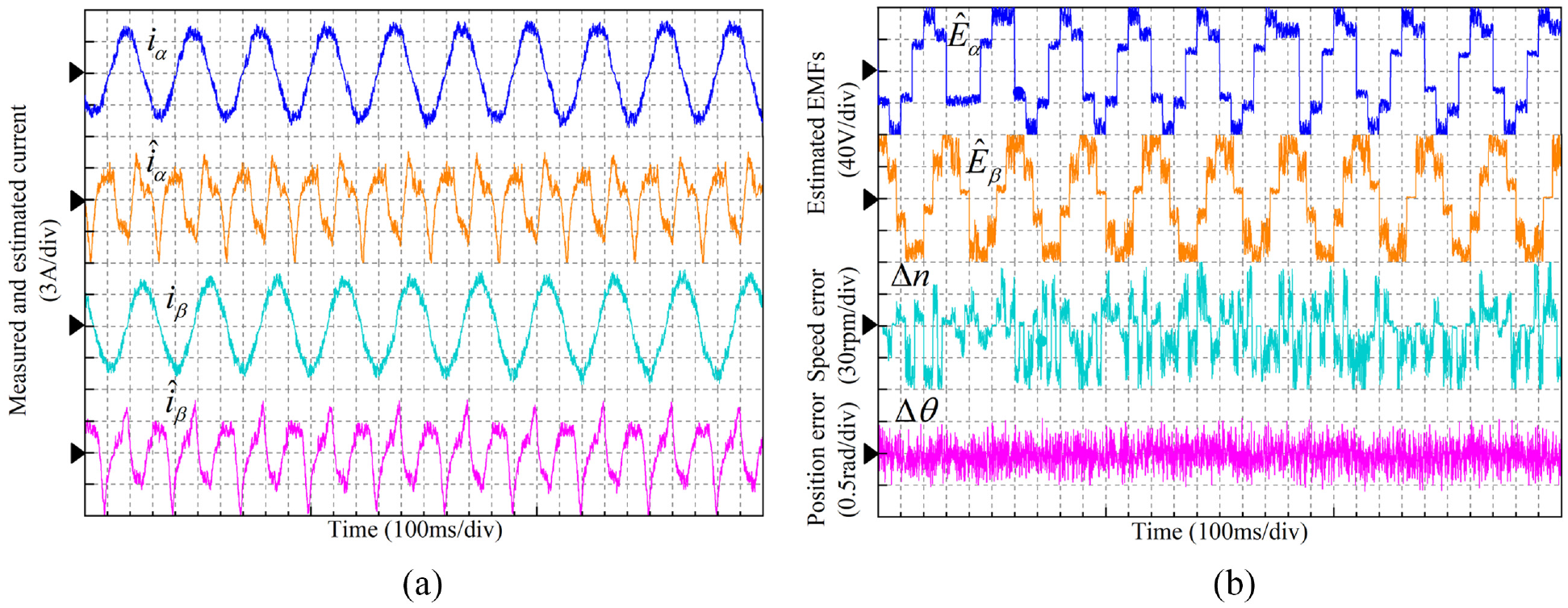
The experimental results of the PLL-based SMO method at high carrier ratio: (a) measured and estimated current and (b) estimated EMFs, speed and position error.
The experimental results of the PLL-based SMO method at low carrier ratio: (a) measured and estimated current and (b) estimated EMFs, speed and position error.
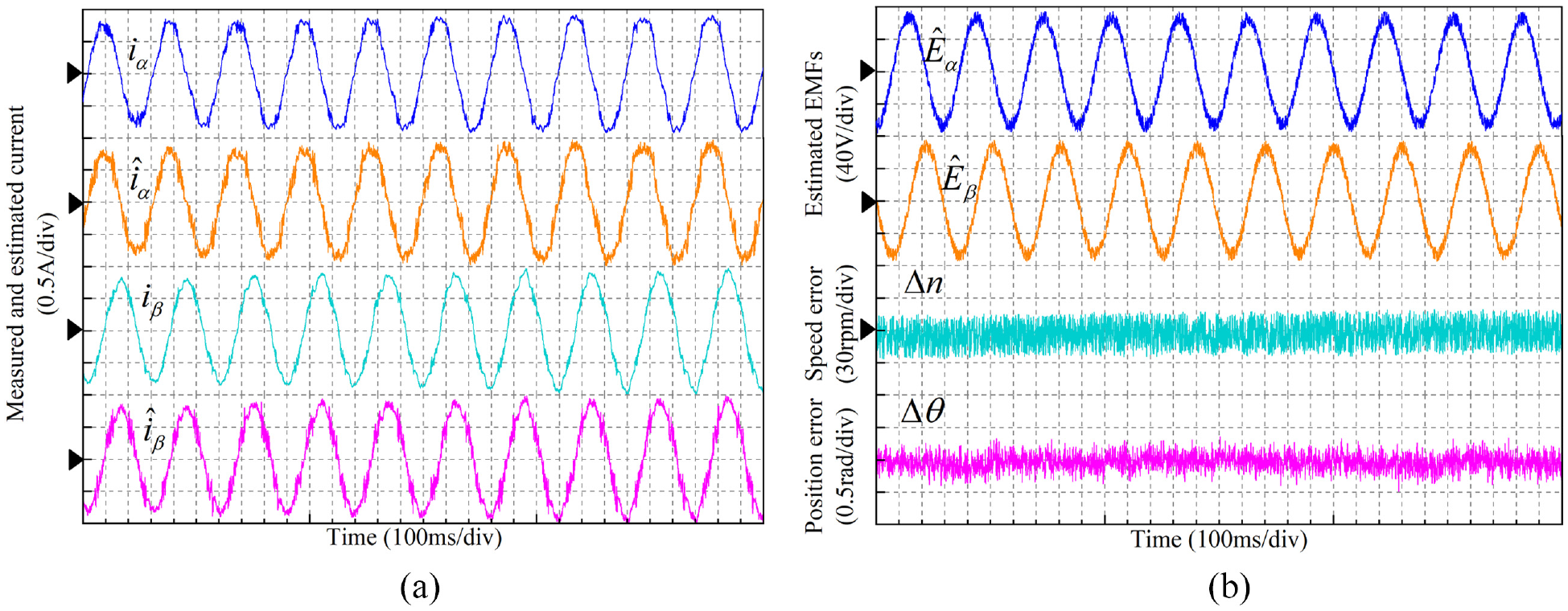
The experimental results of the AOPR_PE method at high carrier ratio: (a) measured and estimated current and (b) estimated EMFs, speed and position error.

The experimental results of the AOPR_PE method at low carrier ratio: (a) measured and estimated current and (b) estimated EMFs, speed and position error.
Standard deviations of two methods at high and low carrier ratios.
Under high carrier ratios, Figure 11(a) represents the measured and estimated values of the α-β currents in the SMO method, and Figure 11(b) represents the estimated EMF and the speed and position errors in the SMO method. Figure 11 indicates that the estimated current can track the sampled current stably, and the estimated EMFs is not distorted. The standard deviation fluctuation of speed and position error is small, which indicates that the speed and position estimates are fairly close to the measured values.
Under low carrier ratios, Figure 12(a) represents the measured and estimated values of the α-β currents in the SMO method, and Figure 12(b) represents the estimated EMF, speed error, and position error in the SMO method. Figure 12 indicates that the estimated currents are significantly distorted, unable to track the measured currents stably. The EMFs estimation shows a large number of harmonics, severe distortion, and chattering. The standard deviations of the speed and position errors are 12.9091 and 0.2053, respectively, with large fluctuations, which are not conducive to the smooth control of the PMSM.
Figure 13 represents the experimental results of the AQPR_PE method under high-carrier ratio conditions. It can be seen that, under high carrier ratios, the estimated current of the proposed method can track the measured current stably, with stable EMFs estimation, subtle chattering, small error fluctuations, and standard deviations of the speed and position errors of 5.8579 and 0.1316, respectively. The tracking accuracy is high.
Figure 14 shows the experimental results of the AQPR_PE method under low-carrier ratio conditions. It can be seen that, although the estimated current fluctuations increase and the EMFs chattering increases, it can still track the measured current stably. The standard deviations of the speed and position errors are 6.3405 and 0.1539, respectively. Compared with the AQPR_PE method under high carrier ratios, although the fluctuations increase, the stability is present. In contrast with the SMO method, the estimated current and EMFs of the proposed method fluctuate less under different carrier ratios and can track the measured values stably. Although the performance of the AQPI_PE method decreases under low carrier ratios, there is no serious distortion and chattering, and the rotational speed and position estimations are accurate.
To verify the parameter robustness of the method proposed in this paper, the parameter estimation was carried out in terms of converge to the actual values under complex dynamic conditions of variable rotational speeds and loads. Figure 15 represents the experimental results of the parameter estimation for resistance and inductance under dynamic conditions, where a load of 6 N. m is added at t = 1s, the speed changed abruptly from 600 rpm to 1000 rpm at t = 2 s, and the load is removed at t = 3 s.

The experimental results of parameter estimation under dynamic conditions.
As can be seen from Figure 15, the estimation results show a convergence process because of the alternating parameters during the motor start-up phase; however, a steady state is quickly achieved. After adopting the method proposed in this paper, the average resistance in a steady state is 1.8551, with a standard deviation of approximately 0.0195, showing an effective estimation of the resistance. The mean value of the inductance estimation is 6.6821 with a standard deviation of approximately 0.0275. When the load is added, the current increases, causing an intensified magnetic field saturation and lower inductance. The opposite characteristics are shown when the load is removed. The estimation results show that the method is effective in identifying the parameters under dynamic conditions.
Figure 16 compares the control performance before and after the estimation. From Figure 16(a) and (b), it can be seen that before estimation, the speed pulsation is larger, and the speed error fluctuates significantly with a standard deviation of 7.8062. Meanwhile, the position errors exhibit a rising trend, and chattering is aggravated with a standard deviation of 0.1823. The position errors increase with rotational speed. From Figure 16(c) and (d) show that, when the parameter estimation results are fed back to the control model, the rotational speed and position errors and the fluctuations decrease, with standard deviations of 6.2467 and 0.1551, respectively. The results indicate that the method can enhance the parameter robustness, reduce the rotational speed and position errors, and improve the estimation accuracy.
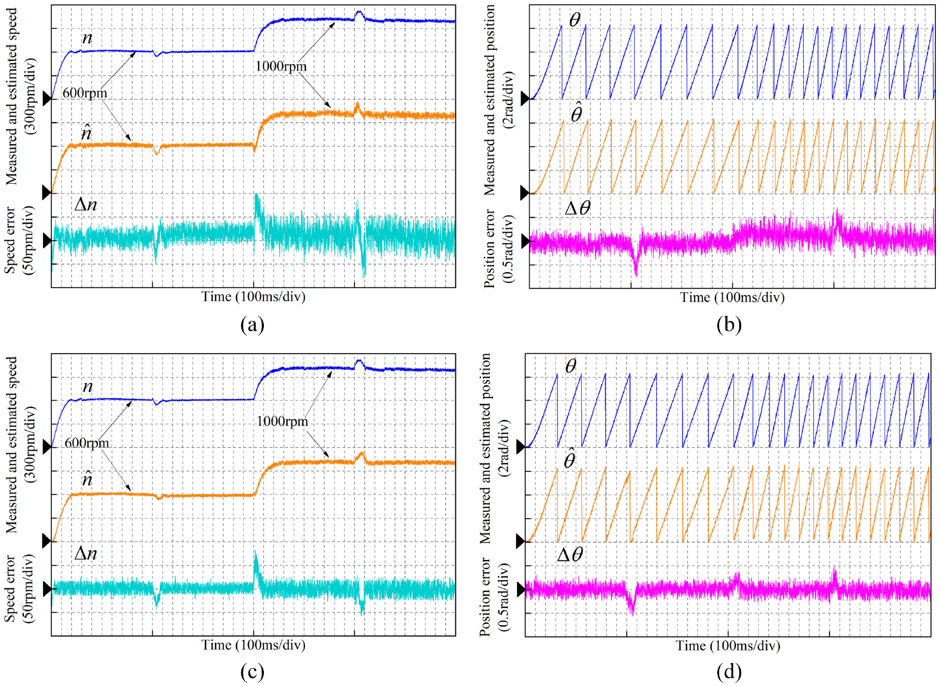
The experimental results of AQPR_PE method before and after the estimation: (a) speed performance before estimation, (b) position performance before estimation, (c) speed performance after estimation, and (d) position performance after estimation.
Summary
The sign function and the LPF in conventional SMO causes chattering and phase shift, degrading the PMSM control performance at low carrier ratios. In order to improve the control performance, this paper proposes an AQPR controller to estimate the EMFs. Its frequency characteristics and adaptive filtering are used to improve the accuracy of rotational speed and position estimation. Meanwhile, the motor parameters in the control model are estimated online and fed back to the controller to enhance the parameter robustness. The results show that the method has high tracking accuracy and parameter robustness under different carrier ratios and complex working conditions.
It is worth noting that the control model built in this paper is analyzed based on the mathematical model of PMSM and is suitable for PMSM operation at medium and high speeds. When PMSM runs at extreme low speed, it is difficult to extract useful signals from the system, and the control method based on mathematical model has certain limitations. Therefore, more methods should be adopted to solve complex problems in the future work.
Footnotes
Appendix A
Express equation (14) as equation (A1)
Among them,
According to Popov’s hyperstability theory, if the parameter estimation model is to be stable, the equation (A2) needs to be satisfied.
where γ is a finite positive real number.
Equation (A2) can be rewritten as equation (A3)
Taking ρ1 as an example, equation (A3) is simplified to obtain equation (A4)
Combining equations (18) and (19), equation (A4) is transformed into equation (A5)
Decompose equation (A5) into equation (A6)
For any function f(t) satisfy the inequality as equation (A7)
Construct equation (A8)
Substituting equation (A8) into equation (A6) yields equation (A9)
Substituting equation (19) into equation (A6) yields equation (A10)
Combining equation (A9) and equation (A10), it is proved that equation (A11) holds
Therefore, it can be concluded that the parameter estimation model satisfies Popov’s hyperstability theory, and the model is stable.
Handling editor: Chenhui Liang
Declaration of conflicting interests
The author(s) declared no potential conflicts of interest with respect to the research, authorship, and/or publication of this article.
Funding
The author(s) disclosed receipt of the following financial support for the research, authorship, and/or publication of this article: This research was funded by the National Natural Science Foundation of China (No.71601180).
Data Availability
The data used to support the findings of this study are included within the paper.