
Abstract
Two-stroke Aviation Piston Engines are multivariable systems with severe non-linear dynamics, making their modeling challenging for control engineers. Although many studies have been conducted on simplified modeling of four-stroke gasoline engines and large-scale two-stroke diesel engines for automobiles and ships, only a few have focused on the general modeling of small two-stroke aviation engines. Thus, extensive research on a general modeling method for two-stroke aviation engines is required. A general non-linear Mean Value Engine Model (MVEM) of two-stroke aviation piston engines is developed. Various parts of the model are represented by appropriate empirical equations that require little engine data and easily fit different engines. The objective is to develop a general and accurate method for rapid engine modeling that captures the main dynamics and can create control systems for two-stroke aviation piston engines. The model is validated using HIRTH-3203 and NU-57 measurement data, and the results show that the issues of fitting simplicity and general applicability are well addressed. Finally, the air-fuel ratio control based on the model predictive control method is carried out on the HIRTH-3203 MVEM, which demonstrates the effectiveness of the proposed MVEM in the controller design and evaluation. The proposed model may support the application of new control technologies, such as adaptive control and intelligent control, in the two-stroke aviation piston engine systems.
Keywords
Introduction
Two-stroke aviation piston engines have the advantages of being compact, lightweight, producing a high-power output per unit displacement, having a simple structure, being convenient to use, and requiring little maintenance. With the rapid development of Unmanned Aerial Vehicles (UAVs) in recent decades, two-stroke aviation engines have been widely used.1,2 The development of autopilot flight management has also promoted the automatic control technology for two-stroke aviation engines, such as the exploration of adaptive control, 3 health monitoring,4,5 and intelligent control with online learning capabilities.6,7 Dynamic engine models are widely used in the design of engine control systems, 8 and higher requirements are put forward for the generality of engine modeling methods, in addition to the simulation fidelity of dynamic characteristics and stationary performances.
Engine modeling is an important tool for the development of engine control systems since it provides effective testing and simulation possibilities. 9 Various engine modeling techniques have been reported to have been used to study engine steady-state performance and transient response in the current literature. These engine models include transfer function models, Mean Value Engine Models (MVEMs), computational fluid dynamics models, and zero-dimensional models. 10 Among them, the more complex modeling methods, such as computational fluid dynamics models, can more accurately represent the engine’s working process but require a greater amount of calculation time and input data. 11 MVEM is a type of simple mathematical engine model which is characterized by a good balance between model accuracy and modeling simplicity. The time scale of MVEM is just adequate to describe accurately the change of the mean value of the most rapidly changing engine variable. This feature enables the model to predict engine dynamic performance in time, which is useful for engine control applications. 12 The MVEM has been widely used in the research of real-time simulation and control of automobile and ship engines. Most of these engines are four-stroke gasoline engines and large two-stroke diesel engines.10,13–16
The typical MVEM was proposed by Elbert Hendricks in 1990. 12 Since then, various MVEMs have been proposed, most of which are models for specific types of engine control systems.8,17 MVEMs for given engines can achieve high accuracy, with static performance errors of less than 2%. 10 High precision is achieved by increasing the complexity of the model and customizing some parameters at the expense of the model’s generality and simplicity. For example, calculating airflow into the crankcase requires several component parameters, such as the geometry size and elastic modulus of the reed valve. 18 However, these part parameters are difficult to obtain by engine users, which makes modeling more challenging. In the fuel injection dynamics module of those MVEMs, the fuel evaporation time constants and the fuel proportion placed on the intake manifold or close to the intake valve are often given by equations using high order polynomial to obtain more precise results. 19 These equations require a significant amount of data support during the modeling process. In addition, crankshaft torque, the main output of the crankshaft dynamic module, is often written as a function of ignition advance angle, air-fuel ratio, crankshaft rotation speed, and single-cycle intake of the cylinder in these custom MVEMs.18,20 The parameter identification method often obtains the coefficients of these torque functions based on numerous test data.21,22 Since the available sources of engine test data are scarce and engine airborne testing is very expensive, a powerful alternative for developing controllers for aviation engines is to use control-oriented simulation models. Currently, it is necessary to establish a general MVEM of two-stroke aviation engines for control applications.
This paper is aimed to establish a general model for various types of two-stroke aviation piston engines, which has the advantage of supporting rapid modeling. In the model layout, the crankcase and cylinder module is added to MVEM for two-stroke engines. The modules of the well-known MVEMs are screened according to their generality. In particular, the applicability of the two forms of the engine shaft dynamics module was analyzed and verified using the test data. These two types of shaft dynamics are based on the empirical equations of indicated shaft power and shaft torque. The verification results are combined with the characteristics of the two-stroke piston aviation engine to improve the model’s accuracy. Specifically, modifications were made to the engine shaft dynamics module, crankcase, and cylinder module. These adjustments are physical and keep the model generic and easy to use. The shop trial data of two different two-stroke aviation piston engines further verified the revised general model. To further demonstrate the effectiveness and potential of the proposed MVEM in the control field, the air-fuel ratio (AFR) control simulation based on model predictive control (MPC) is carried out for HIRTH-3203. In the Simulink environment, HIRTH-3203 MVEM works well and completes a typical control simulation process.
The main contributions of the paper can be summarized as follows: (1) A general MVEM for a two-stroke piston engine was developed by using full empirical formulas to describe its four submodules. (2) The crankshaft dynamics module and scavenge model of the general model have been adjusted, which makes the MVEM close to the dynamics of a small-displacement two-stroke aviation engine. The relative mean error of the adjusted generic model is within 5%, with good accuracy to support the control study. And (3) the accuracy and potential of the MVEM in the control field are verified by the test data and the control simulation respectively, which is the prospect of the MVEM development in Hendricks. 8
The rest of this paper is organized as follows: In Section 2, the general MVEM for the two-stroke engine is illustrated and the engine’s four dynamic submodules are modeled separately. Sections 3 and 4 of this paper discuss the issue of model accuracy as a result of the simplifications and combinations of the MVEM configuration for two-stroke piston aviation engines. The potential of the proposed general MVEM for control applications is further demonstrated using the MPC-based AFR control simulation in Section 5. In Section 6 concluding remarks and perspectives are provided.
General model
The generality of MVEM for two-stroke aviation engines
The classical MVEM has already demonstrated good generality as a research foundation. However, the MVEM’s generality in this paper is limited to two aspects. The first is to build the general model structure of the two-stroke aviation piston engines based on the MVEMs of those four-stroke and large displacement two-stroke engines. For the general model’s details, empirical equations from different MVEMs are selected for combination in this section. The second is to replace the sub-modules of the general model that can be improved in generality by adjusted simple empirical equations. These sub-modules frequently adopt customized expressions in those MVEMs established for specific engine control systems to ensure the high accuracy of the model. Replacing these customized expressions is important for model generalization.
MVEM configuration for two-stroke piston engines
The implementation of MVEM combines the quasi-static and volumetric models, dividing the engine into several independent volumetric control units. 23 Figure 1 shows the structure diagram of a two-stroke engine. In this paper, the MVEM of a two-stroke engine is divided into four dynamic sub-modules: the dynamics of intake manifold sub-module, the crankcase and cylinder sub-module, the fuel injection dynamics sub-module, and the crankshaft dynamics sub-module.

Schematic diagram of the intake process of a two-stroke gasoline engine. (The P, T, and V in the figure represent the pressure, temperature, and volume, respectively. Subscripts 0, m, s, and e refer to ambient air, intake manifold, crankcase, and exhaust manifold respectively).
The dynamics of the intake manifold
The ideal gas law and the conservation of air mass in the intake manifold are used to derive the manifold pressure state equation. 8

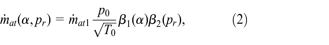
where the air mass flow into the engine port is
The throttle air mass flow is given by the equation 8
where


With

Crankcase and cylinder module
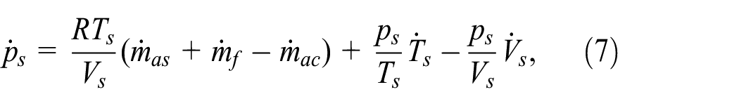
It is different from a four-stroke engine, where the intake air passes through the intake manifold and enters the crankcase before entering the cylinder in a two-stroke engine, as shown in Figure 1. The Crankcase pressure state equation is derived using the conservation of air mass in the crankcase and the ideal gas law:
where the air mass flows passing through the cylinder
The speed-density equation can be used to calculate the mass flow of the mixture swept from the crankcase into the cylinder,

where

and the air mass inducted per stroke is

The temperature in the crankcase affects the engine’s charging efficiency, which can be calculated using the following equation:

the volume of the crankcase varies with piston displacement and can be expressed as:
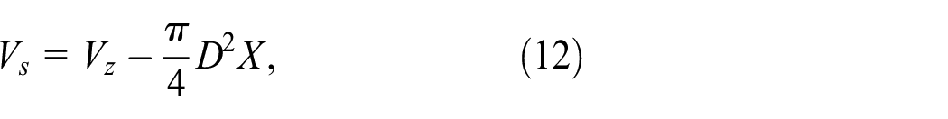
where
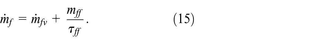
Fuel injection dynamics
Aquino 25 proposed the most popular and simple film flow model. This model keeps track of the fuel mass in the intake manifold and can be written as:
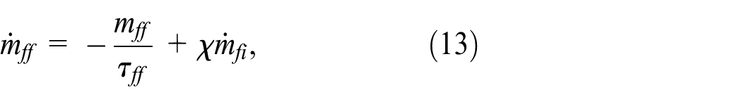

The injected fuel flow is the input of this sub-model, and the engine intake valve fuel mass flow is the output, which is assumed to be in the vapor phase. This model contains two parameters. The first is the time constant for fuel evaporation, and the second is the fuel proportion placed on the intake manifold or near the intake valves. They are determined by the model’s various conditions and can be expressed as the following equations, respectively 17 :


Crankshaft dynamics
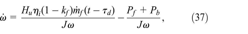
The crankshaft speed state equation can be written as 8 :
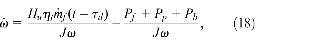
where

The thermal efficiency is composed of four components, as follows 24 :


The engine torque can be expressed as 26 :
this crankshaft speed state equation is based on power and efficiency, and the model equipped with this module is referred to as Model-P in this paper.
The equation for crankshaft speed state can also be written directly in terms of the fuel flow and an algebraic equation 8 :

the engine torque can be given as below 8 :

In this paper, the model equipped with this module is referred to as Model-T.
MVEM performance
The steady-state operation of the two-stroke aviation engine HIRTH-3203 was simulated by using both the Model-P and Model-T developed in the MATLAB-Simulink environment. The main engine characteristics and the required input data were extracted from the engine manufacturer’s product data sheet. 27 The steady-state performance data for the engine were derived from engine shop trial measurements. Table 1 contains the primary engine parameters.
HIRTH-3203 engine parameters. 27

The simulations were run under steady-state operating conditions at 34%, 40%, and 46% of the engine throttle position to validate both models. These data were analyzed in the laboratory engine shop tests, as shown in Table 2. The engine torque and fuel consumption performances of both models and the engine shop tests are shown in Figures 2 and 3. Table 3 shows the percentage error between the shop trial data and both models’ respective predicted engine performance parameters.
Part steady-state test data of HIRTH-3203 engine.


Comparison of engine torque measurement and predictions from Model-T and Model-P: (a) 34% throttle position, (b) 40% throttle position, and (c) 46% throttle position.

Comparison of fuel consumption measurement and predictions from Model-T and Model-P: (a) 34% throttle position, (b) 40% throttle position, and (c) 46% throttle position.
Errors of the initialized general models.

The most striking observation to emerge from the data comparison was:
(i) The errors between the shop trial data and the initial general models combined with the empirical equations from those MVEMs are large. The performances of Model-P and Model-T are insufficient to meet the requirements;
(ii) The error of model-T is very large. Elbert Hendricks’ empirical equation for crankshaft torque should have a suitable application range. It does not apply to the two-stroke aviation piston engine with small displacement;
(iii) Although the performance of the general Model obtained initially is inaccurate, the torque equation of Model-P is based on energy and efficiency, and relevant physical theories support its generality. Some details of Model-P must be adjusted to improve its accuracy. In this paper, the adjusted model is referred to as Model-PA.
General model adjustment and validation
The general model adjustment is implemented based on Model-P and includes changes to the engine scavenging and crankshaft dynamics models. The scavenging model was a component of the crankcase and cylinder module, which determined the quality of the fresh air and fuel mixture that ultimately entered the cylinder. The crankshaft dynamics model is adjusted primarily to correct power losses and the effective combustion fuel quality.
Scavenge model adjustment
Volumetric efficiency is a critical metric for evaluating the engine air exchange process and performance. Compared to a four-stroke engine, the two-stroke engine’s air exchange process exhibits the following characteristics.28–30
The air change time of a two-stroke engine is relatively short, about half to one-third that of a four-stroke engine;
The two-stroke engine has a longer air exchange overlap time, and there is ventilation overlap throughout the scavenging process;
The loss of fresh air during the scavenging process of a two-stroke engine is more severe.
Therefore, a two-stroke engine’s air exchange performance is significantly less than that of a four-stroke engine. Scavenging loss of a two-stroke engine occurs throughout the operation process, comprised of three components: short-circuit loss, mixing loss, and overflow loss.
Additional exhaust components are frequently added to large displacement two-stroke engines to improve scavenging performance. However, small-displacement two-stroke aviation engines often have strict volume and mass restrictions. As a result, they cannot be equipped with additional exhaust devices.
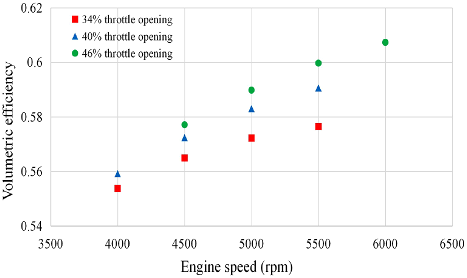
As shown in Figure 4, the volumetric efficiency of the HIRTH-3203 engine calculated from the Model-P is greater than 0.85. However, previous studies31–33 indicate that this value should be between 0.38 and 0.72 for a two-stroke engine, and the volumetric efficiency deduced from the test data also falls below 0.7.

Volumetric efficiency simulation results of Model-P.
The volumetric efficiency calculated by the Model-P does not match the performance characteristics of a small two-stroke engine. The calculated efficiency is significantly greater than the empirical value, which is likely one of the main reasons for the large positive deviation of engine model performance from engine shop tests.
A two-stroke engine operates similarly to a four-stroke engine in terms of intake, compression, combustion, expansion, and exhaust processes, except that a four-stroke engine requires two piston strokes to complete. In contrast, a two-stroke engine requires only one piston stroke. For a two-stroke engine, the volumetric efficiency can also be written as the scavenging efficiency
Volumetric efficiency simulation results of Model-PA.
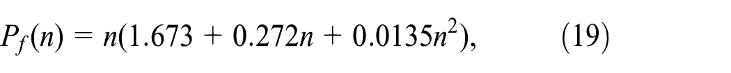
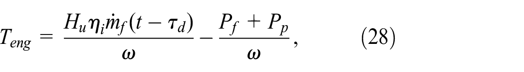
Crankshaft dynamics module adjustment
There is no individual intake and exhaust stroke for a two-stroke engine and its pump loss should be excluded from the calculation of mechanical loss of crankshaft power. Therefore, the crankshaft torque and rotation speed equations can be written as:


The friction loss

where
Model-P torque is calculated using the combustion energy and thermal efficiency of the fuel-air mixture entering the cylinder. Unlike in-cylinder direct injection engines, a proportion of the injected fuel is wasted during the scavenging process of a two-stroke engine due to short circuits and overflow loss. This must be considered in the two-stroke aviation engine model. Therefore, based on the equation (32) and the equation (33), the following results can be obtained by further adjustment

where
Model-PA performance
The engine torque and fuel consumption performances from Model-P, Model-PA, and the engine shop tests are shown in Figures 6 and 7. Table 4 shows the percentage error between the predicted engine performance parameters and the respective shop trial data of Model-PA.

Comparison of engine torque measurement and predictions from Model-T and Model-PA: (a) 34% throttle position, (b) 40% throttle position, and (c) 46% throttle position.
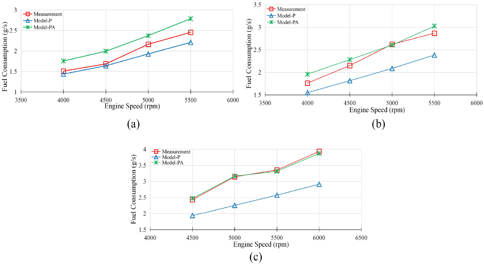
Comparison of fuel consumption measurement and predictions from Model-T and Model-PA: (a) 34% throttle position, (b) 40% throttle position, and (c) 46% throttle position.
Errors of the adjusted general model.

The model’s static performance calculation results demonstrate a significant improvement in the accuracy of the crankshaft torque and fuel consumption characteristics after adjustment. The average error in crankshaft torque performance is 2.29%, and the average error in fuel consumption performance is 3.89%. This error range indicates that the performance of Model-PA can meet the accuracy requirements for a general control-oriented model.
The throttle position, fuel injection, and load torque test data from Table 2 were entered into Model-PA to obtain engine speed under various operating conditions, as shown in Figure 8. The simulation results demonstrate that the engine speed calculated by Model-PA is consistent with the test data as in Table 2.

Simulation results of engine speed from Model-PA.
Figure 9 shows the dynamic simulation results for engine output speed when throttle position changes from 46% to 40%. According to the calculations in this work, the dynamic change in speed following throttle mutation is consistent with the actual dynamic change state of the engine, and the simulation results after stabilization are consistent with engine test data.

Dynamic simulation results of engine output speed from Model-PA.
In addition, the fuel injection map for HIRTH-3203 is determined using Model-PA simulation results, as shown in Figure 10. The results demonstrate a high degree of agreement between the theoretical analysis and the test results. The fuel injection map can be used as the initial manifold absolute pressure (MAP) diagram, which is commonly used in the development of electronic control systems for gasoline engines.35,36

Simulation results of fuel injection map from Model-PA.
The Model-PA performance simulation results indicate that the adjusted general model of the two-stroke engine’s power output accurately reflects the HIRTH-3203’s static and dynamic characteristics. Model-PA is well suited for studying the power output and speed control algorithms of two-stroke aviation engines because the general model is composed of empirical formulas, significantly reducing the modeling workload.
Generality validation
A smaller two-stroke kerosene aviation engine with a displacement of 0.057 L is selected for modeling to verify the generality of Model-PA. Compared to HIRTH-3203, the displacement difference is nearly tenfold, posing a challenge to the model’s generality. The main parameters of the NU-57 engine are shown in Table 5.
NU-57 engine parameters. 37

Table 6 summarizes the results of the Model-PA and the engine shop tests. 37 As indicated by the static performance calculation results, the average relative error of crankshaft speed performance is approximately 2.35%, while the maximum relative error is 4.94%. The HIRTH-3203 and NU-57 engines have a large displacement gap and different cylinder layouts. Comparing performance simulation results to test data shows that the model has a high degree of generality for two-stroke aviation engine dynamic modeling.
Engine speed from Model-PA and tests of NU-57.

Model predictive control of the air-fuel ratio
In addition to the static accuracy and generality requirements, the model used for the preliminary study of a controller is also required to perform continuous and stable simulations within its operating envelope. In this section, the MVEM of the HIRTH-3203 engine will be used to design an air-fuel ratio (AFR) controller, which further demonstrates that the general MVEM established in this paper can support control applications. In this section, model predictive control (MPC) is an advanced process control technique widely adopted in the industry as an effective method to deal with large multi-variable constrained control problems.38–40 In this section, MPC is engaged to optimize the injected fuel mass flow to keep tracing the desired AFR.
Control system structure
Based on the obtained MVEM of HIRTH-3203 in section 4, a predictive control strategy was realized for the AFR control, which is illustrated in Figure 11. The throttle position (
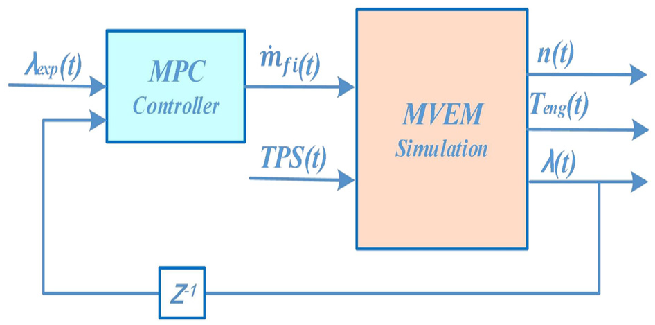
The block diagram of the AFR MPC structure.
MPC uses a model of the system to predict its future behavior and then optimizes a quadratic performance based on the prediction.42,43 The main idea is to choose the control input by solving an optimal control problem repeatedly, aiming at minimizing a performance criterion over a future horizon. The cost function can be expressed as 43 :

where
Simulation results
The HIRTH-3203 MVEM was used in this MPC demonstration. The MPC parameters are manually adjusted to determine the appropriate values by comparing the control performance. The parameters of the nonlinear optimization was chosen as

The step input of the throttle position.

Fuel injection mass flow optimized by the MPC.
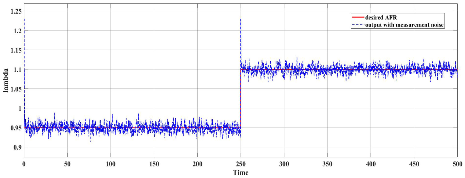
Tracking performance of the desired AFR (normalized).

The output of engine crankshaft speed during the control simulation.

The output of engine crankshaft torque during the control simulation.
The simulation results show that the HIRTH-3203 MVEM can be used to generate data for controller design and evaluation. In the simulation process, the HIRTH-3203 MVEM can characterize the main input-output characteristics in real-time operation. This simulation and control application demonstrate that this low-cost, fast construction and general MEVM can provide effective support for engine control engineers. These traits will be beneficial, especially in the controller design, evaluation, and comparison in an early stage.
Conclusion
This paper establishes a general MVEM for two-stroke aviation engines based on the classical MVEMs of piston engines. Considering the convenience of application in control research, the general MVEM entirely adopts empirical equations to build the engine sub-models, significantly reducing engine modeling time and cost.
The HIRTH-3203 engine was modeled in MATLAB-Simulink, and the model’s details were adjusted based on comparisons between simulation results and test data. These details include the volumetric efficiency calculation, the pump and friction losses corrections, and the fuel flow correction. The adjusted model remains physical, generic, and easy to use. It is apparent that the modified MVEM is suitable for the limited range of small-displacement two-stroke aviation engines and provides an effective tool for modeling. The simulation results of the modified MVEM are compared to the test results once more, demonstrating that the modified MVEM is reasonable and significantly improves accuracy.
Afterward, the modified general MVEM is used to model a small engine (NU-57) with a displacement of only 0.057 L. The modeling process for NU-57 is very convenient, although NU-57 and HIRTH-3203 differ greatly in displacement, fuel type, and cylinder layout. The generality of the modified MVEM is verified by comparing the engine performance calculated by the model with the test data. Furthermore, the AFR control simulation based on the MPC method is carried out on the modified MVEM. The simulation results demonstrate the effectiveness of the proposed modeling method in control applications.
Although the general MVEM established in this paper is not as accurate as the model established for a specific engine, it will be extremely useful to control engineers during the engine modeling process, preliminary controller design, and evaluation. The current findings add to a growing body of literature on the MVEM applied in aviation piston engines and its generality. Future research should focus on investigating the control study of two-stroke engines based on this general MVEM, including but not limited to a control scheme based on neural network and machine learning methods.
Footnotes
Appendix
Handling Editor: Chenhui Liang
Declaration of conflicting interests
The author(s) declared no potential conflicts of interest with respect to the research, authorship, and/or publication of this article.
Funding
The author(s) disclosed receipt of the following financial support for the research, authorship, and/or publication of this article: This work is sponsored by Malaysian Ministry of Higher Education with the Fundamental Research Grant Scheme (FRGS) [grant number FRGS/1/2020/TK0/USM/03/11].