
Abstract
A novel hydro turbine with the ultra-small unit discharge was suggested and studied for the first time. It was specially developed for hydraulic energy recovery with a smaller flow rate and medium available head, its highlight feature is straight blades in the radial direction. In this paper, the theoretical and numerical simulation of a novel hydro turbine was studied. First, with the working process and principles introduced, the theoretical models were established for the prediction of optimal unit speed, optimal unit discharge, and performance curves. Second, numerical simulation was carried out to study the performance of the novel turbine and verify the theoretical models. Different mesh quantity cases were investigated to select an accurate configuration. The numerical simulation predicted that optimal unit speed was 57.07 r/min, and optimal unit discharge was 0.0705
Keywords
Introduction
It is common to see hydraulic energy dissipation in the decompression process, and the hydraulic energy recovery in this process has been widely accepted as a source of clean energy for carbon footprint reduction.1–3 Nowadays, society has focused its attention more heavily on the technologies of carbon emission reduction, moreover, different scenarios of hydraulic energy recovery have been studied by scholars,4–8 and there are three typical categories in these scenarios.
The first category has typical characteristics of large flow rate and low head, such as a series of special hydro turbines have been dedicated to industrial circulating water system for power generation or axial fan driven,9–11 and cross-flow hydro turbine has been developed for the micro hydropower with low head.12–15 The second category has pressure above megapascals, meanwhile the flow rate is less, multistage pump as turbines and Pelton turbine had been used in these scenarios.16–18 Although there is a better carbon emission reduction benefit, the payback period is long.19–21
Finally, the third category has smallest discharge while the available head is between both categories above. In addition, it is the most common one. One typical scenario is reverse osmosis unit used for high quality reclaim water.22–24 Statistics of the standard 100 t/h reverse osmosis units show that the available head of concentrated waste water is among 50–80 m, while the volumetric flow rate is between 30 and 50
In this study, the novel hydro turbine has been researched by CFD and theoretical models. Although theoretical models are built on numbers of assumptions, but indispensable. CFD has been widely used in design, which can be used to analysis the flow filed and performance of each subdomain separately.26–28
This paper is composed of five sections: The first section is “Introduction.” In Section “Methodology,” the methodologies were established for the novel turbine. In Section “Numerical simulation,” CFX was selected for numerical simulation and mesh independence was verified. In Section “Results and discussion,” the comparison results between theoretical calculation and numerical simulation were carried out, subsequently, the novel turbine performance were improved by a tail energy recovery runner. Section “Conclusions” was devoted to reporting the conclusions of this work.
Methodology
Working process
Figure 1(a) shows the flow passage of the novel hydro turbine on front view, the outstanding feature is radial straight blade runner (radial straight blade runner; RSB runner) whose blades are straight in radial direction. The RSB runner was inspired by the fluid coupler, which has radial straight blades in pump and turbine, meanwhile, the transmission efficiency is high. 29 These characteristics are in accordance with the requirements of the novel hydro turbine.
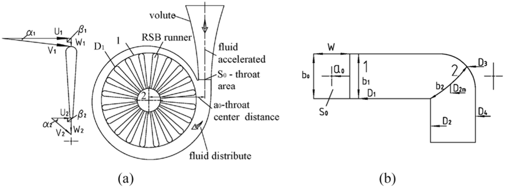
Flow channel of the novel hydro turbine: (a) flow passage on front view and (b) meridional flow channel.
In addition, the radial straight blade adopts a bighead profile in order to reduce the head loss for deviating from rated working conditions. RSB runner with dense cascade will get a strong constraint to fluid. In particular, the RSB runner with large blade height is different from conventional hydro turbine whose blade height is valued according to a specific speed.
In the working process, fluid is accelerated in the contraction section at volute inlet and then velocity moment was determined by throat area. As shown in Figure 1(b), there is no guide van for fluid distribution, because head loss of the guide van will be increased rapidly while the opening is too small. Therefore, the velocity moment and water distribution were directly controlled by spiral volute. Finally, the velocity moment will be consumed in centripetal flow process with runner rotating, but a small part of the velocity moment will be discharged at any working conditions.
Working principles
From Euler’s equation, equation (1) is obtained:

where, H is head,
In any operating conditions, the velocity moment at runner inflow is equal to that in volute throat on the assumption that the fluid flow in volute is irrotational. But the ignorance of friction will cause significant deviation while the velocity of fluid is high, therefore coefficient ξ is brought in for correction. According to the relations above, equation (2) is obtained. Equation indicates that the velocity moment at runner inlet is proportional to volumetric flow rate:
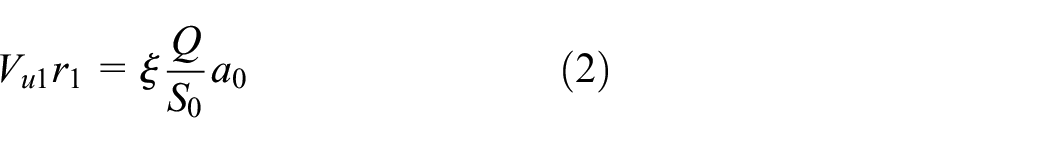
where
Based on the assumption that the velocity triangle at outlet is right triangle at any conditions, it is easy to get the result that outlet velocity moment is

where
In any working conditions, equation (4) can be derived from equations (1) to (3). The effective head

It is worth emphasizing that the velocity triangle at inlet of the runner is right triangle only in rated working condition, then equation (5) can be obtained according to the right velocity triangle:

where
The velocity moment at runner inflow is equal to that in volute throat after correction, of course, it is also applicable for the optimal conditions. The velocity moment at runner inlet could be calculated through equation (2) and velocity triangles separately, then equation (6) can be obtained:

where
Optimal unit speed
The unit speed has been defined as
Equation (5) is Euler’s equation for the novel hydro turbine in rated working conditions. In order to establish the relationship between the optimal unit speed

where
The ranges of these parameters of the novel hydro turbine are recommended based on current limited research,
Optimal unit discharge
The unit discharge of hydro turbine has been defined as
Equation (6) shows the velocity moment at runner inflow is equal to that in volute throat, in order to establish the relationship between the optimal unit discharge

Equation (8) shows that the optimal unit discharge
The section of volute throat can be rectangular or circular. For the convenience of theoretical analysis, the equivalent radius
According to the analysis above, equation (9) is obtained, which shows

For the novel hydro turbine,
Unit discharge – unit speed
In any working conditions, equation (10) is obtained from equation (4) and the definitions of
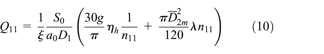
In order to simplify the equation, the coefficient
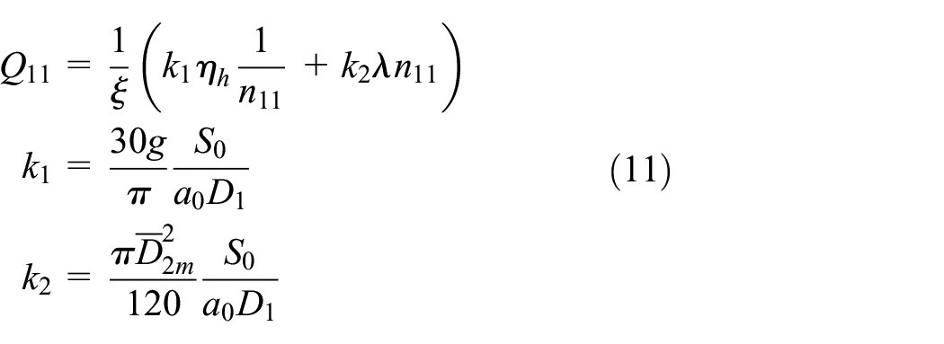
It is obvious that there is only one curve of
For the novel hydro turbine, it is known that the range of
Numerical simulation
Geometric model
Diameter of RSB runner
Equation (11) derived from equation (5) can be used to calculate the diameter of RSB runner. The calculation of the diameter depends on the parameter’s estimation. Finally, the available head is 62 m,

Outlet diameter
According to the right velocity triangle, the kinetic energy loss caused by velocity circumferential component


Equation (14) shows that
Head loss calculation in different outlet diameter.

Blade height
Figure 2(b) shows blades with two different height of 15 mm and 25 mm, and Figure 2(a) shows comparison of the runner efficiency. It demonstrates that the efficiency is higher for the runner with blade height of 25 mm. Furthermore, a larger height will reduce the manufacture difficulty of runner. It is noteworthy the elevation z should be ignored if the gravitational acceleration field is neglected in the numerical simulation, and the unit of volumetric flow rate Q is m3/s except the unit has been indicated:
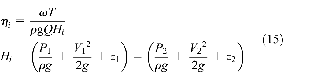
where
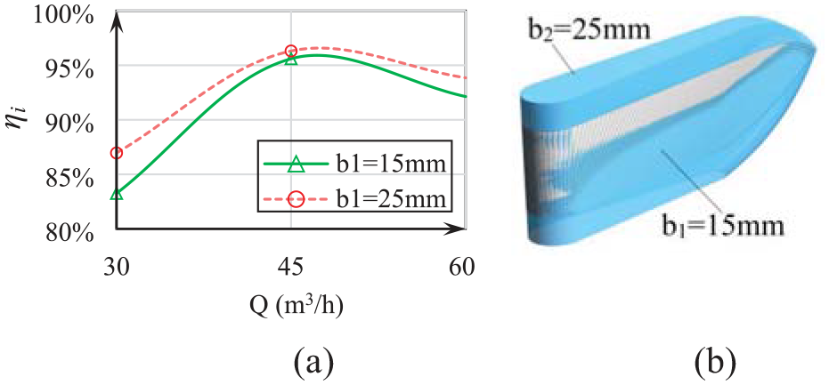
Different blade height effect on efficiency.
Main structure parameters
Main structure parameters of the novel hydro turbine are listed in Table 2.
Main structure parameters.

Boundary conditions
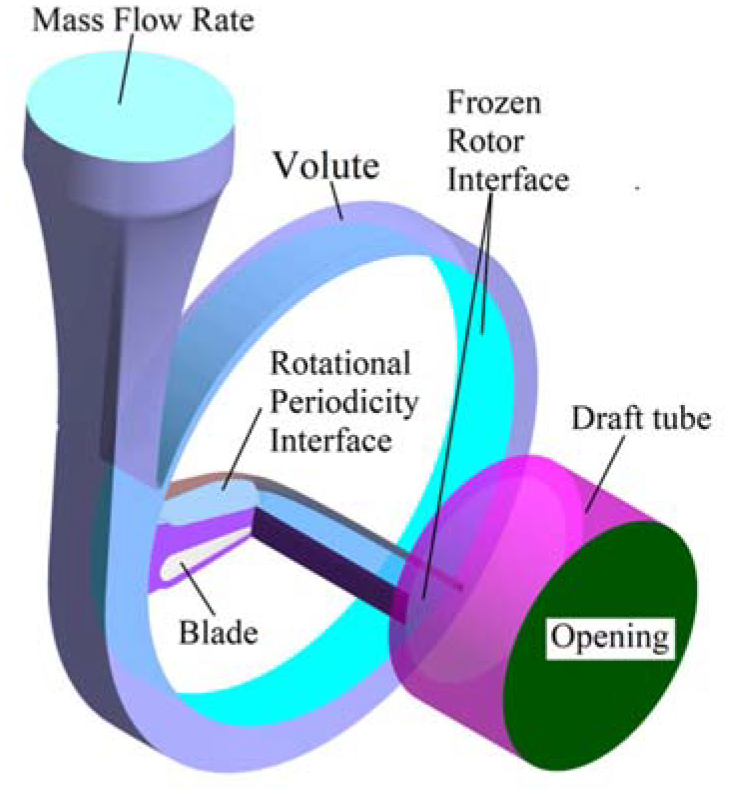
Figure 3 shows the boundary conditions of flow domains. The novel hydro turbine had been divided into three flow domains, including volute, RSB runner, and draft tube. First, the commercial software ANSYS CFX was selected for numerical simulation. Second, the volute inflow boundary was set as mass flow rate, and then the outflow boundary was set as opening and the pressure value was 0 Pa. Third, one single periodic flow channel of RSB runner was adopted for numerical simulation. Although the flow field of RSB runner will be different between one single periodic and full periodic, but the prediction deviation rate of unit parameters is between 2% and 3%, the deviation can be ignored for simplify the study. Lastly, frozen rotor interface was selected between flow domains, and the pitch angle of RSB runner was determined by blade number. Rotation speed was 3000 r/min, and the wall boundaries were set as no slip:

where ζ is prediction deviation rate,
Boundary conditions of the computational domains.
Mesh independence verification
In order to ensure the accuracy of numerical simulation, the mesh independence was verified by head comparison in five cases that with different mesh number. At first, the hexahedra mesh for volute and draft tube is divided by ICEM, and hexahedra mesh for RSB runner is divided by TurboGrid, as shown in Figure 4. It is noteworthy that the single periodic channel of runner is cited in numerical simulation, and the mesh number is listed in Table 3. Second, the boundary conditions of five cases will be kept in the same, the mass flow rate at volute inflow is all set as 12.46 kg/s, and other boundary conditions are consistent with that in the previous section. Third, based on the numerical simulation results, the head of different cases were compared in Figure 5. When the total mesh number is larger than 1149 thousand (case C), then the Head deviation is less than 0.2%, the mesh number of case C is accurate for numerical simulation. Finally, the case D with mesh number of 1560 thousand is selected.
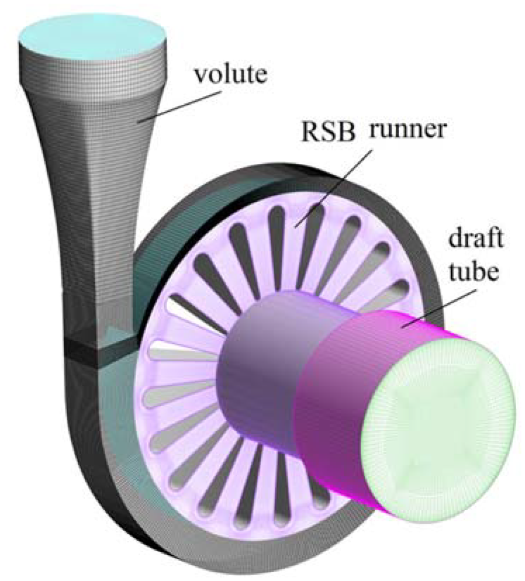
Full flow domain mesh in hexahedra.
Mesh number of subdomains.


Numerical prediction on head for different mesh number.
Results and discussion
Optimal unit parameters
Theoretical models are indispensable for engineering applications because it provides another way to predict the performance of the novel hydro turbine, although the accuracy depends on a series of empirical parameters. Meanwhile, numerical simulation is used to verify the adaptability of the theoretical models and study the performance of the novel hydro turbine.
The optimal unit speed could be calculated through equation (7), then the ranges of parameters were selected that
The optimal unit discharge is theoretically calculated by equation (8). The value of
Numerical simulation is carried out at rated working point, then the numerical simulation results are compared with theoretical calculation. The comparison is listed in Table 4, which shows a small deviation between numerical simulation and theoretical calculation. Results of theoretical calculation are closer to that of the numerical simulation while λ is 1.3, ξ is 0.8 and
Theoretical and numerical prediction results.

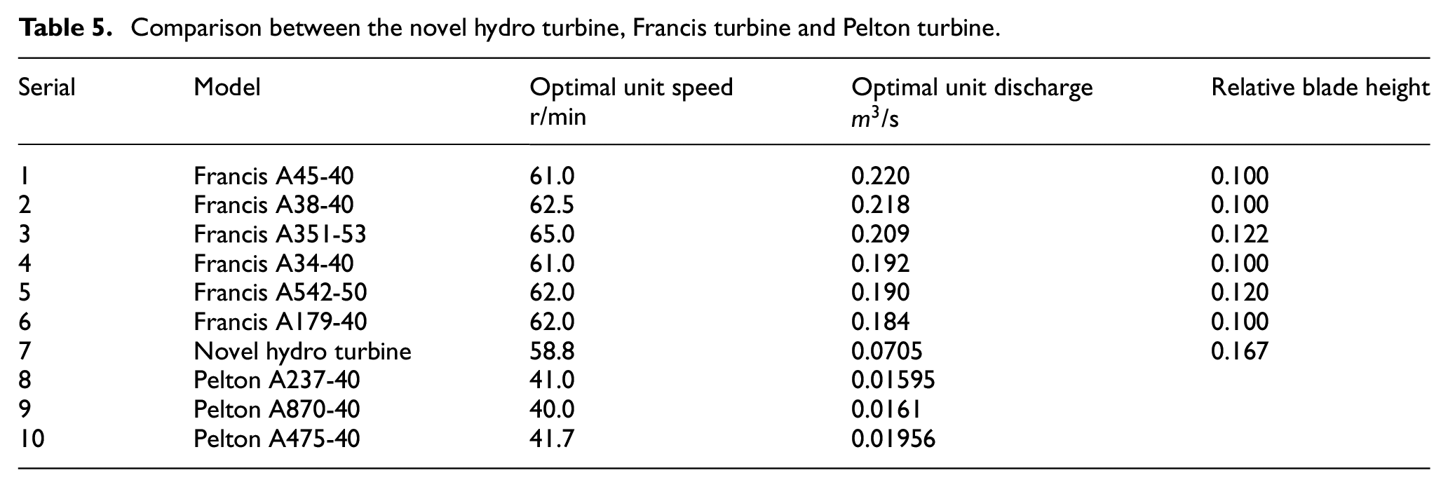
Comparison between the novel hydro turbine, Francis turbine and Pelton turbine are shown in Table 5, which shows that the optimal unit discharge
Comparison between the novel hydro turbine, Francis turbine and Pelton turbine.
Unit discharge–unit speed curve
The unit discharge–unit speed curve is important for the novel hydro turbine, one way to obtain this curve is based on numerical simulation. With different working conditions calculated by changing flow rate, a series of unit speed and unit discharge will be obtained. Then, these points are plotted in one figure and joined by one smooth curve.
Another way to obtain the unit discharge–unit speed curve is based on equation (10). First, two important coefficients
These points from numerical simulation and theoretical calculation were plotted in Figure 6, which shows that curves are closer in a large flow range, but the deviation becomes obvious as the flow rate decreases. Meanwhile, the comparison shows that the unit discharge of all working conditions is ultra-small discharge.
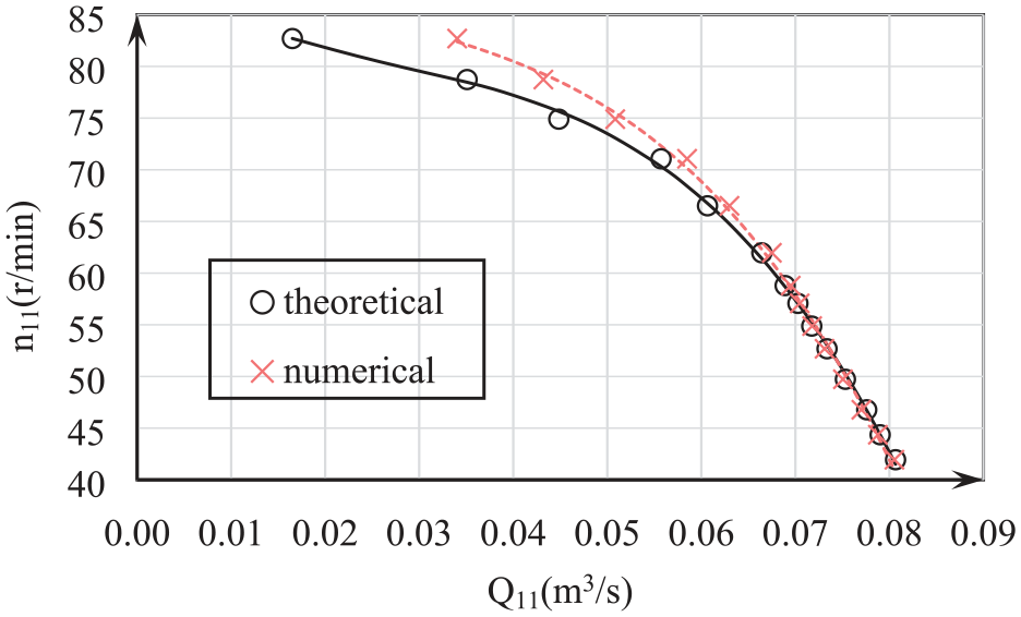
Comparison of theoretical and numerical predicted performance curves.
Velocity moment distribution
The prediction of velocity moment is essential for power output calculation. Figure 7 shows the velocity moment distribution along tailing edge at rated working condition, these curves are, respectively, predicted by numerical simulation and theoretical model. Theoretically, the velocity moment is calculated by
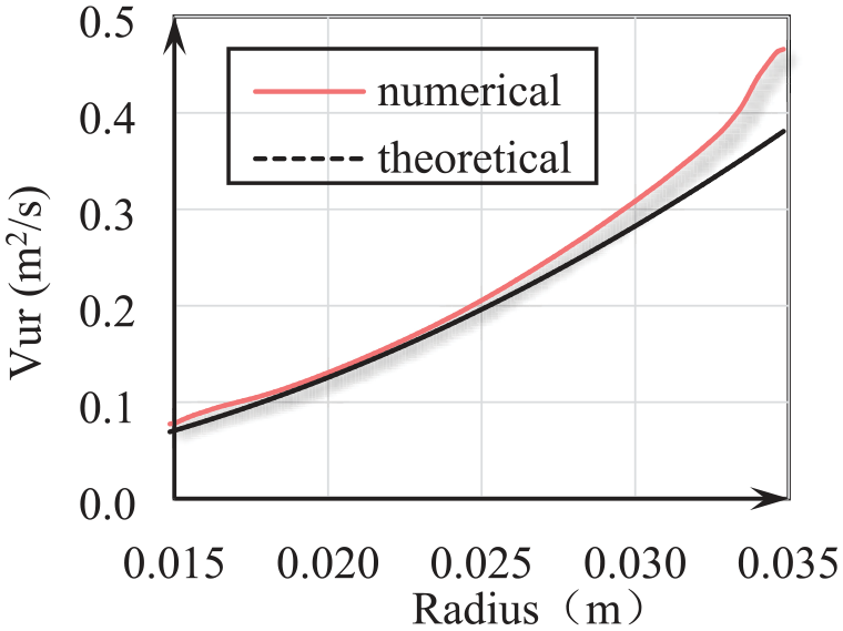
Velocity moment distribution prediction at tailing edge.
Flow field of RSB runner and volute
Figure 8(a) shows the blade loading curves of RSB runner blade, and the transversal lines are shown in Figure 8(b). The blade loading distribution is uniform with the flow rate of 45
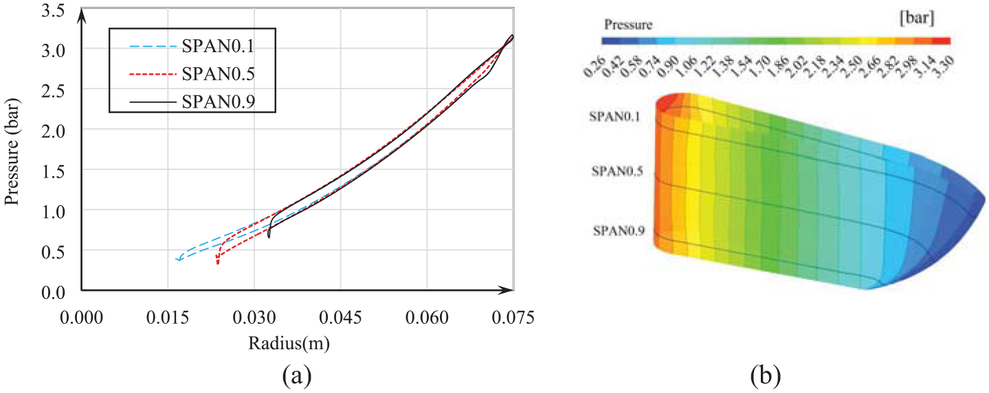
Blade load distribution: (a) blade loading curves and (b) pressure distribution.
Figure 9 shows the flow field of volute and RSB runner on top view. Figure 9(a) shows a negative impact angle at inlet, which results in partial fluid separation on pressure side. Figure 9(b) shows that there is no impact angle on the blades leading edge. Figure 9(c) shows an obvious positive impact angle at inlet, and it leads to a vortex nearby suction side. Although there being positive or negative impact angle at inlet and local fluid separation at inlet, but the flow field will be restored to a good status in the flow passage, because the dense cascade has a strong constrain on fluid.

Flow field of RSB runner and volute: (a) Q = 40
Performance improvement by TER runner
The efficiency predicted by numerical simulation is lower than 80%. One reason is that the velocity moment at outlet is not consumed completely, so the decrease of velocity moment at outlet should be considered. A tail energy recovery runner (tail energy recovery runner; TER runner) is proposed and installed coaxially at the outlet of RSB runner, which performs a supporting role for velocity moment recycling and increases the power output, as shown in Figure 10.
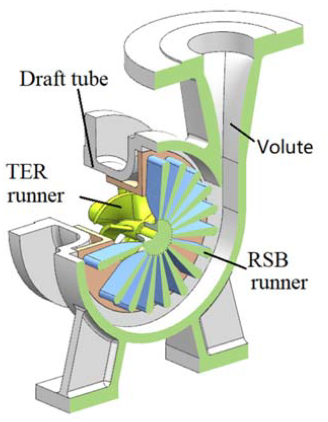
Components of a novel hydro turbine with TER runner.
The TER runner is closed to RSB runner and its diameter is
The mounting angle at outlet is determined by the velocity triangles, assuming that the outlet velocity is along normal direction at rated working condition, then the outlet mounting angle can be calculated by equation (17). According to the above results the TER runner can be designed:

where
The comparison between the novel hydro turbine with and without a TER runner is carried out, as shown in Figure 11. The efficiency of the novel hydro turbine with TER runner is improved and the maximum efficiency reaches to 84.5%. The velocity moment at outlet is reduced to −0.013 m2/s by TER runner, and the output power is added of 1.124 kW. Meanwhile, the unit discharge–unit speed curve is changed, because part of head will be consumed by TER runner while recycling the velocity moment.
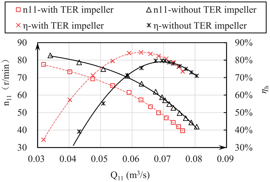
Performance comparison of the novel hydro turbine with and without TER runner.
Figure 12 shows streamlines in TER runner. Although the efficiency has been improved by the TER runner, there is a slight positive impact angle at inlet shown in the rectangle line, which means that the structure of TER runner should be optimized in the further study.

Flow field of TER runner.
Conclusions
In this present study, a novel hydro turbine with ultra-small discharge was suggested for the first time. According to the study results, the following conclusions can be made:
(1) The theoretical models of novel hydro turbine were established, and the range of main parameters had been described for theoretical calculation, moreover, the optimal unit discharge with ultra-small characteristic was demonstrated.
(2) Based on main geometric parameters obtained from theoretical calculation, numerical simulation was carried out with the optimal unit speed of 57.07 r/min, optimal unit discharge of 0.0705
(3) Deviation of performance curves between numerical simulation and theoretical calculation is very small in large flow range, which means the performance of the novel hydro turbine can be predicted by the theoretical models.
(4) The efficiency of novel turbine was improved by TER runner, and the maximum efficiency was improved from 79.6% to 84.5%.
Footnotes
Appendix
Handling Editor: Chenhui Liang
Declaration of conflicting interests
The author(s) declared no potential conflicts of interest with respect to the research, authorship, and/or publication of this article.
Funding
The author(s) disclosed receipt of the following financial support for the research, authorship, and/or publication of this article: This research was supported by the National Natural Science Foundation of China (51579104, 51909094).