
Abstract
Aiming at the problem that the change of motor parameters in actual operation will significantly reduce the control accuracy of the motor, this paper proposes a sensorless control method of permanent magnet synchronous motor based on an adaptive back-EMF observer. Firstly, in the sensorless vector control algorithm, the mathematical model of the permanent magnet synchronous motor based on the coordinate axis transformation is established, online identification of permanent magnet synchronous motor flux linkage, and the adaptive back EMF observer is constructed. The parameters update the motor model to achieve accurate control of the rotor position and speed of the permanent magnet synchronous motor. Then the back-EMF observer and the adaptive back-EMF observer are verified in the simulation environment. Then the simulation model of the back-EMF observer and the adaptive back-EMF observer is carried out, and the comparison analysis is made. Finally, a permanent magnet synchronous motor control platform is built in the laboratory, and the method proposed in this paper is verified. The results show that, under the condition that the permanent magnet synchronous motor parameters change, the online identification of the parameters and the accurate speed of the permanent magnet synchronous motor can be realized control.
Keywords
Introduction
The rapid development of motor control theory has made it increasingly urgent to accelerate innovation. The innovation of control methods is not only the need for industrial control in the new situation, which adapts to the current economic development situation. The motor speed control theory has been continuously improved through practice and made into products widely used in existing motor control systems.1,2
The importance of the value created by motor operation for the country’s economic development cannot be overstated. Permanent magnet synchronous motor (PMSM) is widely used in industry, transportation, coal mining machinery, and other occasions because of its high power density, high reliability, wide speed range, and other advantages. 3 To make a permanent magnet synchronous generator play a better role in the application process, the control method of the permanent magnet synchronous engine is extensively studied. Specific methods such as variable voltage frequency control methods, 4 model predictive control methods, 5 and vector control methods. 6 The vector control method is superior to other control methods, such as variable voltage frequency control. It can achieve the same control performance as DC motors and simplify the control of permanent magnet synchronous motors. Therefore, the vector control method is chosen to control the permanent magnet synchronous motor.
In the vector control system, the current information is decomposed by coordinate transformation. The excitation and torque current is adjusted according to different control targets to achieve precise speed and torque control. For current decoupling and coordinate transformation, mechanical sensors are generally used to obtain rotor position and speed information. 4 However, in practice, sensors increase the motor’s size and the system’s cost. The sensors are difficult to install and maintain in harsh environments, reducing the system’s reliability. Therefore, new control strategies need to be studied to improve the performance of the permanent magnet synchronous motor control system, and the use of sensorless technology is an excellent solution to mechanical sensors triggering defects. Many scholars have proposed many methods to estimate the rotor speed and position based on the sensorless control of permanent magnet synchronous motors and have made significant progress. Alvaro Mendoza et al. 7 proposed a sliding mode approach based on a built-in permanent magnet synchronous motor speed regulation design without a speed sensor to achieve rotor speed and stator resistance estimation. They proved that the proposed method has better robustness and control performance.
Yongle Mao et al. 8 proposed a sensorless control strategy with online adjustment of rotational inertia for high dynamic performance with good control performance in response to the deterioration of the sensorless control system due to the uncertainty of rotational inertia. Ming et al. 9 used an adaptive law-based PI control method to control the motor speed based on the study of model reference adaptive system (MRAS) sensorless control. Liu et al. 10 studied a new speed control method based on sliding mode control and disturbance observer for a permanent magnet synchronous motor drive system. It is also demonstrated that the designed controller has a fast transient response and robustness under different operating conditions. Xiaoyi et al. 11 proposed a variable structure PID controller that can effectively improve the control performance of the motor to control the motor speed. The above study is to propose solutions to the problems that affect the control performance. Nevertheless, no consideration is given to the change of motor parameters, which can reduce the accuracy of motor speed control.
The accuracy of the control system for permanent magnet synchronous motors is becoming more and more demanding in various fields, and the control system must obtain the precise parameters of the controlled object in real time to meet the requirements of the control system. In a sensorless control system for permanent magnet synchronous motors, precise motor parameters are required for accurate estimation of rotor position and speed. However, in some cases, the operating conditions such as high temperature and demagnetization due to long-term operation, as well as the motor’s own losses, will make the actual parameters of the motor will be inconsistent with the parameters set out of the motor, and the changed parameters will affect the accuracy of the sensorless control of the motor control. 12 Many scholars, at present, perform motor parameter estimation by parameter identification methods. Zhu et al. 13 addressed the problem that the stability and convergence response speed of the model reference adaptive identification (MRAI) algorithm cannot be combined simultaneously, and used a particle swarm optimization algorithm to optimize the model reference adaptive gain coefficients to achieve fast and stable identification of rotational inertia. Heng et al. 14 proposed a permanent magnet synchronous wind turbine control based on position sensorless and online identification of motor parameters for the effect of generator parameter time-variability on rotor position observation accuracy. Wang et al. 15 need to identify the motor parameters in order to achieve accurate control of rotor position and speed. The traceless Kalman filter (UKF)-based state estimation for parameter identification of permanent magnet synchronous motor is proposed, and the identified parameters are used in the vector control algorithm to update the motor model for high accuracy speed and position estimation. Rafaq et al. 16 proposed an online identification method for accurate estimation of stator resistance and shaft stator inductance for model-based effective internal permanent magnet synchronous motor sensorless control by online parameter identification for sensorless control. In vector control system, the control system depends on the design of the speed control loop is reasonable, and the speed control loop needs to obtain the parameters of the permanent magnet chain to achieve accurate control of the motor speed.
This paper addresses the problem that changes in the parameters of a permanent magnet synchronous motor can make the speed control of the motor inaccurate. A sensorless control method for permanent magnet synchronous motors based on an adaptive back-EMF observer is proposed. Firstly, the vector control method is used to coordinate transform and current decoupling for the established permanent magnet synchronous motor model and adjust the current parameters of different coordinate axes to realize the control of speed and torque. Second, a back-EMF observer is designed to estimate the PM synchronous motor speed and rotor position. Then, the permanent magnet synchronous motor parameters are designed for online identification, and the identified parameters are used to update the motor model. Finally, an adaptive back-EMF observer is constructed to realize online parameter identification of the magnetic chain of permanent magnets and motor speed loop control, and the method effectively improves the performance of the permanent magnet synchronous motor control system. The contributions of this paper can be summarized as follows: (1) Design sensorless vector control of permanent magnet synchronous motor. The mathematical model of a permanent magnet synchronous motor was built, and then the coordinate transformation and current decoupling were carried out based on the motor model. Adjust the current parameters of different axes to achieve the control of motor speed and torque. (2) Design a back-EMF observer to estimate the speed and rotor position of the permanent magnet synchronous motor. (3) For the parameter change of the permanent magnet synchronous motor, the design parameters are identified online based on the sensorless control of the permanent magnet synchronous motor. The identified parameters are updated in the motor model. (4) Designing an adaptive back-EMF observer based on the back-EMF observer, combined with parameter online identification, to realize online parameter identification of the magnetic chain of permanent magnets and motor speed loop control. This method allows the back-EMF observer to estimate the rotor position and speed with improved estimation accuracy.
Motor model and control method
To simplify the system operation of a permanent magnet synchronous motor, it is necessary to establish a mathematical model of a permanent magnet synchronous motor based on coordinate transformation 17 to solve the complex nonlinear motor control problem. When the mathematical model of the PMSM is simplified, it needs to be transformed by coordinates in the stationary three-phase coordinate axis into a mathematical model in the two-phase rotating coordinate system. Vector control is to achieve decoupled control of the PMSM. The decoupling control of PMSM needs to control the excitation current and torque current, respectively, and transform the two-phase stationary coordinate system into the two-phase rotating coordinate system.
Mathematical model of PMSM
To simplify the analysis of the mathematical model of the permanent magnet synchronous motor, the following premises are set constant.
(1) Ignore the eddy current loss and hysteresis loss of the motor;
(2) Ignore the harmonic effect of the motor, and consider that the stator windings of each phase are 120 degrees different from each other and completely symmetrical;
(3) When the motor is running in rated condition, the actual parameters of the motor are considered to be unchanged.
In the mathematical model of the permanent magnet synchronous motor, the components of the stator voltage under the ABC three-phase stationary coordinate axis can be expressed:


Through

The voltage vector is then transformed from the


Vector control
In the vector control method for permanent magnet synchronous motors,
18
this control system usually utilizes

To obtain an estimate of the rotor position and rotor speed, the permanent magnet synchronous motor’s counter-electromotive force must be obtained first. Then the position of the motor rotor and the rotor speed is estimated by an algorithm.
Adaptive back-EMF observer
Back electromotive force observer
The phase-locked loop can accurately estimate the rotor speed and position of the motor. PLL phase-locked loop control19,20 is a classic method for estimating motor speed and position in motor control. According to the voltage formula of the

By inverse solution, find the relation of

The

The speed of the rotor can be estimated:

The logical process of the rotor position algorithm of a permanent magnet synchronous motor is shown in Figure 1.

Algorithm for motor rotor position.
The position of the rotor can be obtained through the
Parameter online identification
In some cases, permanent magnet flux may change due to operating conditions such as high temperature and demagnetization during long-term operation and motor losses. The rotor position and velocity of a permanent magnet synchronous motor are challenging to estimate by the back electromotive force observer accurately, so the online identification of permanent magnet flux is essential. Therefore, it is necessary to design an online identification system for motor parameters. 21
Model Reference Adaptation,22,23 Architecture Reference Model, and Tunable Model. The theoretical design of the parameters to be identified should construct an adjustable model. The mathematical model of the permanent magnet synchronous motor and the algorithm for estimating the permanent magnet flux linkage of the permanent magnet synchronous motor should be the reference model. The key to identifying model reference adaptive parameters is to construct a correct and appropriate parameter adaptive law so that the difference between the two model outputs gradually converges and finally tends to be infinitely small. The identification result is obtained.
Adaptive parameter identification model
The model reference adaptive method can be used to identify motor parameters in real time. The adaptive parameter identification system is mainly composed of reference model, adjustable model, and parameter adaptive criterion. The block diagram of the system is shown in Figure 2. The basic principle of MRAS is to give the reference model and the adjustable model the same input

Basic structure of a model reference.
Motor current equation:

According to the structure of the above formula, three state variables, a, b, and c, introduced:

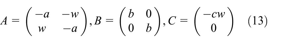
Moreover, by introducing the variables A, B, and C, the following expressions can be obtained:

Among them,
In the online identification of the parameters of a permanent magnet synchronous motor, the adjustable model is formulated as follows:


Thus, both the reference model and the adjustable model have been expressed, and in order to compare the two, formula (12) is subtracted from (14) to obtain the following procedure:
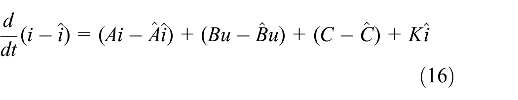
In order to make the form of the expression more standardized and to carry out a reasonable transformation, the parameter to be identified is to be designed in the form of a proportional integral, then the following definition is made first:

And satisfies the following equation:

And take

There is an error in the adjustable model and the reference model values, defining the state error.

Rewrite equation (18) as follows:

where
After adaptive law adjustment until the difference gradually converges to zero, the parameters of the permanent magnet chain of the motor are identified.
System stability analysis
Assume that

Then it means that the model reference adaptive control system is asymptotically stable.
Introduce a scalar function

where
The characteristic root of
System simulation
Back-EMF observer
In this paper, a simulation model of the adaptive back-EMF observer sensorless control system is built in Matlab/Simulink platform to validate the relevant algorithms and schemes. Figure 3 shows the simulation of the back-EMF observer.

Sensorless control of the back-EMF observer.
The parameters of the permanent magnet synchronous motors involved are shown in Table 1.
Motor parameters.

The back-EMF observer uses the control strategy of

Counter-electromotive force and rotor position.
The solid line in Figure 4 is electric potential
Figure 5 shows the electric potential

Counter-electromotive force and rotor position.
Adaptive back electromotive force observer
To verify the effectiveness of sensorless control based on an Adaptive back-EMF observer. Based on the above control principle, the adaptive back-EMF observer model in Matlab/Simulink is shown in Figure 6.

Sensorless control with adaptive back-EMF observer.
Compared to the back-EMF observer, the adaptive back-EMF observer phase changes the magnetic chain of the permanent magnet synchronous motor from 1 Wb to 1.14 Wb. In contrast, other motor parameters do not change.
Figure 7 shows the magnetic chain difference relationship graph, which is the difference between the permanent magnet magnetic chain estimated by the adaptive back-EMF observer and the actual magnetic chain of the motor. The mean value of the error
Magnetic chain differential relationship.
Figure 8, where the solid line is the actual speed of the PMSM, and the dashed line is the motor speed estimated by the adaptive back-EMF observer. Where the speed given in the simulation of 50 rad/s is changed to 60 rad/s, the motor speed can be accurately estimated by the adaptive back electromotive force observer within 0.4–1 s by changing the speed given in the simulation to 60 rad/s. The rotor speed of the permanent magnet linear synchronous motor reaches 60 rad/s after 0.02 s at 1 s with a sudden increase of 50 N.m load. The estimated speed is also at 60 rad/s, with little error between the actual and estimated speed. It shows that the method can effectively identify the magnetic rotor chain in real time and can effectively estimate the rotational speed with high estimation accuracy, which meets the real-time motor control requirements.

Speed of motor.
Model comparison
The models of ground back-EMF observer control system and adaptive back-EMF observer control system are established. To study the case of motor parameters changing the ground, the permanent magnet chain of permanent magnet synchronous motor 1 Wb, changed to 1.14 Wb, and analyze the two systems for the estimation of the actual speed of permanent magnet synchronous motor.
Figure 9 shows that the chain parameter of the permanent magnet synchronous motor, initially 1 Wb, is changed to 1.14 Wb. The chain parameter of the input electric potential is changed. The difference between the motor speed estimated by the back-EMF observer and the actual speed of the permanent magnet synchronous motor is about 2.1 rad/s with a significant error. Since the motor parameters change during operation, the speed estimated by the back-EMF observer needs to be more accurate.

Back-EMF observer.
Figure 10 shows the simulation of the adaptive back-EMF observer. In the figure, the error between the actual speed of the motor and the estimated speed of the adaptive back-EMF observer is 0.23 rad/s, which can be seen from the figure that the error is minimal. The results show that the adaptive back-EMF observer can accurately identify the motor flux. The control performance of the adaptive back-EMF observer is better than that of the back-EMF observer.

Adaptive back-EMF observer.
Experimental validation
In order to verify the correctness of the theoretical analysis, an experimental study is conducted for a permanent magnet synchronous motor. A 2.2 kW PMSM vector control platform is built to verify the adaptive back-EMF observer. The power supply and motor parameters used in the experiments are consistent with the simulation parameters using MOSFET as the power switch, using TMS320F28335 as the control core; the supply voltage is 27 V; the PWM frequency is 20 KHz. Figure 11 shows the permanent magnet synchronous control platform.

Experimental platform.
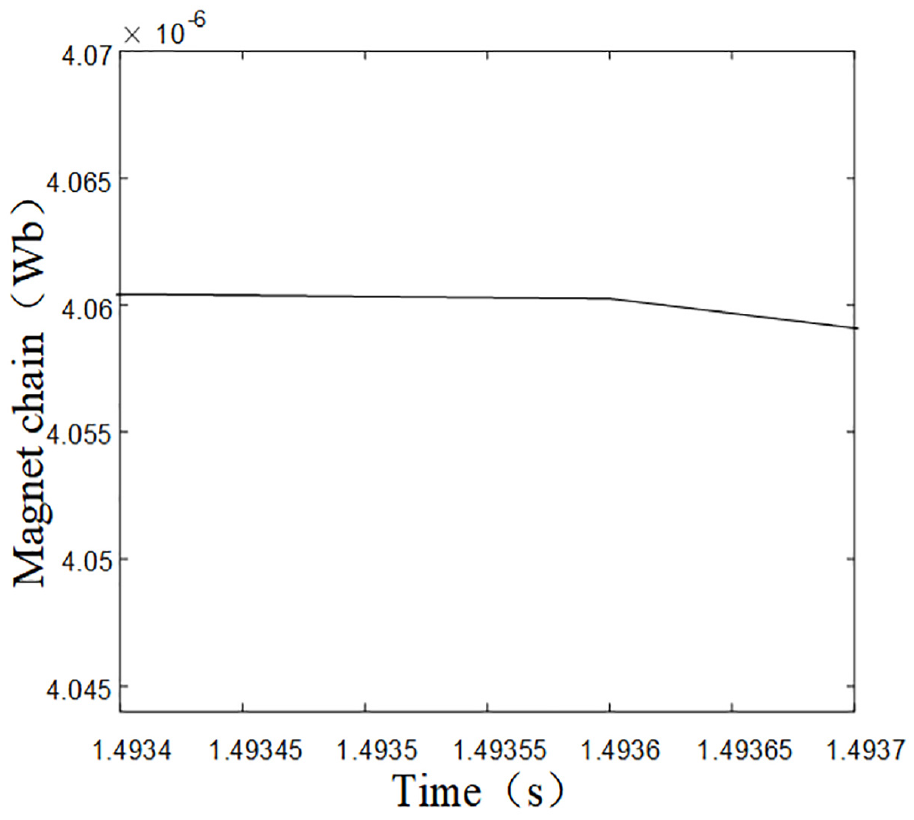
Figure 12 shows the magnetic chain difference graph, and the difference between the two is about 0.0059 Wb. The error is close to zero, illustrating the accuracy of the adaptive back-EMF observer in estimating the magnetic chain of the permanent magnets.

Magnetic chain difference relationship diagram.
Figure 13 shows the adaptive back-EMF observer updating the identified permanent magnet chains to the motor model after the permanent magnet synchronous motor’s chains are changed. The solid line in the figure is the actual speed of the motor, and the dashed line is the estimated speed of the permanent magnet synchronous motor. The estimated motor speed differs little from the actual speed of a permanent magnet synchronous motor. The results show that the back-EMF observer can accurately estimate the speed of the motor under the condition that the flux link of the permanent magnet changes.

PSMS speed.
The solid line in Figure 14 shows the actual speed of the PM synchronous motor, and the dashed line shows the motor speed estimated by the phase-locked loop. The rated speed is 50 rad/s, and the speed overshoot at startup is about 8%, which is within a reasonable range. The system surges the motor load to 50 N.m load at 1 s, and the adaptive back-EMF observer can update the motor model with the identified parameters so that the speed of the permanent magnet linear synchronous motor can reach 50 rad/s again.

Load change.
Conclusion
(1) To address the problems of motor parameter variations and low accuracy of estimated rotor position in actual operation, which can significantly reduce the control accuracy of the motor. Design of phase-locked loop method and vector control method for accurate estimation of back EMF and rotor position. Adaptive back-EMF observer to identify the magnetic chain of the permanent magnet synchronous motor online and update the motor model with the identified parameters to control the speed of the permanent magnet synchronous motor accurately.
(2) Simulation models of the back-EMF observer and the adaptive back-EMF observer are developed. The comparison results show that the adaptive back-EMF observer can effectively identify the variation of the magnetic chain of the permanent magnet and estimate the rotor position and speed with high estimation accuracy, which can meet the real-time requirements of motor control.
(3) The method proposed in this paper is verified by building a permanent magnet synchronous motor control platform in the laboratory. The results show that the adaptive back electromotive force observer can realize the accurate control of permanent magnet synchronous motor speed.
Footnotes
Handling Editor: Chenhui Liang
Declaration of conflicting interests
The author(s) declared no potential conflicts of interest with respect to the research, authorship, and/or publication of this article.
Funding
The author(s) disclosed receipt of the following financial support for the research, authorship, and/or publication of this article: The authors would like to acknowledge the National Natural Science Foundation of China (Grant No. 51875451) and the National Natural Science Foundation of China (Grant No. 51834006).